VQX-939ASD-MICSmart Guard Halogen Light
Aurum Electronics Corp.
Click to zoom
Application Details
- Equipment Class
- DSC - Part 15 Security/Remote Control Transmitter
- Date of Grant
- Dec 11, 2007
- Application Purpose
- Original Equipment
- Date of Application
- Dec 11, 2007
- Equipment Note
- Smart Guard Halogen Light
- Frequency Range
- 433.92000000 - 433.92000000
- Company
- Aurum Electronics Corp.
- Country
- Taiwan
Documents & Files
Document Text
Text extracted from the exhibit documents filed with the FCC. Open a document above to read the original.
Users Manual
Manual Contents: A. 939ASD kit contents B. 939ASD overview C. Definition D. Programming your 939ASD E. Mounting the 939ASD F. Driver installation G. Viewing image H. Technical Specifications I. General Information and Safety J. FCC information A. 939ASD kit contents z Model 939ASD Lighting Camera z Camera driver: CDROM driver for Windows 98/2000/XP z User Manual z 1M USB cable & 1G SD card z Accessory bag: screws, wall plugs, 1pc allen key, 3pcs 1.5V AAA batteries B. 939ASD overview Fig. 1 C. Definition 1. Definition of front view parts (see fig. 1) Floodlight cover:Open to replace a new halogen lamp. Floodlight:For lighting purpose Halogen lamp:For lighting purpose, please use the correct voltage and watts of halogen light for this product. Halogen lamp, max power is 300W Cam Lens:this is the digital camera lens, please use a soft cloth to clean if needed. PIR lens:Passive Infrared Lens. Low Battery Indicator (hidden inside the lens) 1) Red lamp will start to flash when the battery is going to be out of power. 2) If the battery is out of power, the date of system may be lost and cause the system abnormal. 2. Definition of back view parts (see fig. 2) Floodlight screw:Used to open or close the flood light case to install the halogen lamp. Time control knob:For adjusting the illumination time of halogen floodlight power Adjust to “-” where the minimal time is 40 seconds;adjust to “+” where the maximal time is 7 minutes. Sensitivity control knob: Adjust to the range of Passive Infrared Motion Sensor where can be detected. AC cable outlet:For connecting the external AC cable to 939ASD 8 Positions DIP switch: 256 sets of changeable system code is available 1) To select a system code simply move some of the eight slider-switches in the RF transmitter unit –leave some in their original position. This is now your system code; the slider-switches in your RF receiver unit must now be set in the same pattern. Make a note of the settings on a piece of paper, so you can double-check your code without having to re-open the RF transmitter unit. 2) Make sure the 8 Positions DIP switch of 939ASD is the same as the setting of receivers and remote control. Fig. 2 3. Definition of side view parts (see fig. 3 & 4) 3 position switch:for functions selection 1) Light + camera + speaker: detection for all day Daytime and nighttime: light, camera and speaker are all in operation 2) Light at night + camera all day + speaker in the daytime Daytime: light is off, camera is on, speaker is on Nighttime: light is on, camera is on, speaker is off. 3) Light at night + camera all day + speaker at night Daytime: light is off, camera is on, speaker is off. Nighttime: light is on, camera is on, speaker is on. Audio mode:for different sound selection Pre-set default is “Welcome”. Push one time to ”May I help you”, push again to “dog barking”. Push one more time to turn off this function. Control operates in above circular pattern. LED indicator:for indicating the status of function or error situation by different color of LED 1) Red: SD card is not inserted into the SD slot or the system is abnormal 2) Green: 939ASD is recording or USB is inserted and connecting with the computer 3) LED off: stand by(SD card is inserted into the slot), when off button is pressed * Please note when off button is pressed, remove SD card within 30 seconds (now the LED will turn red after SD card is removed from the slot) Waterproofed cover: protects below-listed contents. Interference Connector:For connecting the 939ASD to PC by provided USB cable to PC. SD slot:For inserting the memory card, please push the SD card to the end and make sure that it is properly seated. Reset button: restore functions to default settings 1) Press RESET button one time when turn on 939ASD 2) Please press this button if there is any abnormal situation happen. Off/Rec:Please press OFF button to remove SD card. Please remove card within 30 seconds of pressing the OFF button to avoid loss of data. Fig. 3 Fig. 4 Fig.6 D. Programming your 939ASD 1. Install/replace the halogen lamp (see fig. 5) Make sure to turn off the power of 939ASD or discount the AC outlet Open the floodlight from floodlight screw by screw driver. Take out the Halogen lamp. Place a new Halogen lamp. * Halogen Lamp is 300W Close the floodlight with screw carefully Please make sure the voltage and polarity are correct before connection. Incorrect voltage will damage the camera. If you are not sure, please contact your retailer. 2. Install/replace batteries (see fig. 6) Unscrew the back cover and unscrew the battery cover. Put the 3 provided AAA 1.5V batteries into the batter compartment and make sure the polarity (- +) is placed correctly. Install battery cover and back cover. 3. Set the Data and Time: Install the provided software to your PC (For details, please see F. Driver Installation) Plug provided USB cable from 939ASD to PC Execute the program and click “Play”, when the video is shown on the screen the setup is completed. (The setup of time and date will be the same as computer) Close the program and remove USB cable to complete the setup. 4. Insert/remove SD card(see fig. 7): Unscrew the waterproofed cover by provided allen key, then insert the SD card and lock in place. If you need to remove the SD card, please press OFF button and take it out within 30 seconds. When LED lamp turns green, meaning SD card is being read, do not remove SD card or the data may be lost. Fig. 7 Fig.5 5. Other settings (see fig. 2) Time control:Turn the time control knob to”+” side to increase the illumination time, turn the control knob to “ -“ side to reduce the illumination time. Sensitivity control:Adjust the detector range of Passive Infrared Motion Sensor 8 Positions DIP switch: 1) This product is able to operate with RF wireless receivers. To select a system code simply move some of the eight slider-switches in the RF transmitter unit …
Text truncated - open the document above for the full version.
External Photos
External Photos EUT - Front View EUT - Bottom View EUT – Left Side View EUT – Right Side View
ID Label/Location Info
ID Label/Location FCC ID Label Label Location Information Specifications: Text is Black or white in color and is left justified. Labels are printed in indelible ink on permanent adhesive backing or silk-screened onto the EUT or shall be affixed at a conspicuous location on the EUT. ID Location: FCC ID: VQX-939ASD-MIC
Internal Photos
Internal Photos EUT – Cover off View (1) EUT – Cover off View (2) EUT – Cover off View (3) EUT – Main Board Top Components View EUT – Main Board Bottom Components View EUT – Power Supply Board Assembly Top Components View EUT – Power Supply Board Circuit View EUT – Switch Board Top Components View EUT – Switch Board Bottom Components View EUT – Sensor Board Top Components View EUT – Sensor Board Bottom Components View EUT – Button and Board Components View EUT – Button and Board Circuit View EUT – Camera Board Top Components View EUT – Camera Board Bottom Components View EUT – RF Board Top Components View EUT – RF Board Bottom Components View EUT – Speaker View
Operational Description
AEC-939ASD-MIC Circuit Description While PIR sensor is detecting the signal, it will activate voice circuit, image circuit, 433.92MHz RF circuit and lighting control circuit. Voice circuit is based on MCU to control MIC and SP function Image circuit is based on CPU to control the function of video, SD card transmission, USB transmission and direction light. Lighting control circuit is based on relay construction in order to control the floodlight power. 433.92MHz RF circuit is based on super-regenerative construction by using FM to transmit the signal via antenna.
Schematics
S_IMG0S_IMG1S_IMG2S_IMG3S_IMG4S_IMG5S_IMG6S_IMG7 S_PCK S_HSYNCS_VSYNCSEN_CLK VCC_3V DGNG VCC_25 SCL SDA ROM_A15ROM_A14ROM_A13ROM_A12ROM_A11ROM_A10 ROM_A9ROM_A8ROM_A7ROM_A6 ROM_A1 ROM_A0 ROM_D7 ROM_D6 ROM_D5 ROM_D4 ROM_D2 ROM_D1 ROM_D0 ROM_D3 DGND VCC_25 USB_DET P11 P10 SD_DATA0 SD_DATA2 SD_DATA3 UPIO0 SD_DATA1 ROM_A2 VCC_3V X32KOUT X32KIN DGNDSD_CLK SD_CMD SD_DETA2.5V1DGNDVCC_3V DP DNDGNDPWR_DOWNSD_WPGPIO3VCC_25USB_DETXOUT XIN BAT_LOAGND1GPIO0TEST1GPIO1GPIO7TEST0 VD4 VD1 VD0 VD2 VD3 VD_LDQM VD_CLK VD_CKE VD_UDQM VD_WE VD_CAS VD_RAS VD_CS0 VCC_3V DGND VCC_25 VA_13 VA10 VA9 VA8 VA7 VA6 VA5 VA4 VA3 VA2 VA1 VA0 ROM_A5 ROM_A4 ROM_A3 RST VD5 DGND VD6 VD7 VCC_3V X1 Crystal 12MHz X2 Crystal 32.768KHzMHz C15 C14 C17C16 XOUTXIN X32KOUTX32KIN C18 D5 SW2 R15 R4 R5 GPIO0 GPIO1 R8R9R10R11R12 R7 C19 DPDNUSB_DET VCC_25 VCC_5V R3 VCC_3V VCC_3V VCC_3V G D4 R R14R13 P10P11 R6JP TEST0TEST1 SD_DET SD_DET SD_WP SD_WP SD_DATA2 SD_DATA2 SD_DATA3 SD_DATA3 SD_CMD SD_CMD SD_CLK SD_CLK SD_DATA0 SD_DATA0 SD_DATA1 SD_DATA1 S_IMG(7..0) S_IMG0S_IMG1S_IMG2S_IMG3S_IMG4S_IMG5S_IMG6S_IMG7 SEN_CLK SEN_CLK S_VSYNC S_VSYNC S_HSYNC S_HSYNC S_PCK S_PCK SCLSDA SCLSDA VA13VA(10..0)VD(7..0)VD_CKEVD_CLKVD_RASVD_CASVD_LDQMVD_UDQMVD_WE VA13 VA(10..0)VD(7..0)VD_CKEVD_CLKVD_RASVD_CAS VD_LDQM VD_UDQM VD_WE VD_CS0 VD_CS0 ROM_A(15..0)ROM_D(7..0) ROM_A(15..0)ROM_D(7..0) BAT_LO PWR_DOWN PWR_DOWN UPIO0 UPIO0BAT_LO C9 C10 C11 C3 C4 C5 C6 VCC_3V C13 L1 L2 A2.5V1 AGND1 R39 S_IMG(7..0) C8 C2 VCC_3V RST D6 TOUCH GPIO3 Q1 OFF ON SW3 C20 R1 R2 VCC_3V D3 U1 C1 C7 C12 J1 C21 MODEL NO.: PCB:939ASD+939SW 939SWPCB 939SWPCB AEC-939ASD-MIC/AEC-939ASD/AEC-939AD/AEC-939AS/AEC-939AUAEC-936ASD-MIC/AEC-936ASD/AEC-936AD/AEC-936AS/AEC-936AU VD(7..0)VA(10..0) VA13VD_CLKVD_RASVD_CASVD_CKEVD_UDQM VD_WEVD_LDQMVD_CS0 VA13 VD_CLK VD_CASVD_RAS VD_CKE VD_UDQM VD_LDQM VD_WEVD_CS0 C22 C23 VA0VA1VA2VA3VA4VA5VA6VA7VA8VA9VA10 VA13VD_CLKVD_CASVD_RASVD_CKEVD_UDQMVD_LDQMVD_WEVD_CS0 VD0VD1VD2VD3VD4VD5VD6VD7VD0VD1VD2VD3VD4VD5VD6VD7 VD(7..0) VA(10..0) J2 ROM_A0ROM_A1ROM_A2ROM_A3ROM_A4ROM_A5ROM_A6ROM_A7ROM_A8ROM_A9ROM_A10ROM_A11ROM_A12ROM_A13ROM_A14ROM_A15 ROM_D0ROM_D1ROM_D2ROM_D3ROM_D4ROM_D5ROM_D6ROM_D7 R16 C24 R17 R18 SD_DATA0 SD_DATA1 SD_DATA2 ROM_D0ROM_D1ROM_D2ROM_D3ROM_D4ROM_D5ROM_D6ROM_D7 ROM_D(7..0) ROM_D(7..0) ROM_A(16..0) ROM_A(16..0) VSP_3V ISP_WEISP_OEISP_CE R19 R20 R21 R22 R23 R24 R25 R26 C25 Q2 SD_VCC SD_DET SD_WP SD_DATA2SD_DATA3SD_CMDSD_CLKSD_DATA0SD_DATA1 VSP_3V External Programming ROM SD/MMC CARD SDRAM VSP_3V SD_VCC ROM_A16 U2 J3 U3 PCB:939ASD MODEL NO.: AEC-939ASD-MIC/AEC-939ASD/AEC-939AD/AEC-939AS/AEC-939AU AEC-936ASD-MIC/AEC-936ASD/AEC-936AD/AEC-936AS/AEC-936AU D1 D2 C27 C31 R28 R29 BAT 4.5VIN 5V UPIO0 BAT GNDIN GND UPIO0 VCC_3V Q3 R31 R30 C28 PWR_DOWN PWR_DOWN R27 BAT_LO VCC_25 C30 VCC_5V1 VCC_5V VCC_5V R32 D7 R33 R34 R35 Q4 Q5 C33 TOUCH TXD VSP_3V D8 RF 939SW1PCB C33A U4U5U6 C26 C29 C32 U8 SW4 POWER RF TX PCB:939ASD+939SW1MODEL NO.: AEC-939ASD-MIC/AEC-939ASD/AEC-939AD/AEC-939AS/AEC-939AU AEC-936ASD-MIC/AEC-936ASD/AEC-936AD/AEC-936AS/AEC-936AU C39 R38 VCC_D28 S_IMG7 S_IMG6 S_IMG5 S_IMG4 S_IMG3 S_IMG2 S_IMG1S_IMG0 C37 C38 SEN_CLK SDA SCL S_HSYNC S_VSYNC S_PCK L3 L4 C34 C35 VSP_3V SEN_CLK SEN_CLK S_VSYNC S_VSYNC H_VSYNC H_VSYNC S_PCK S_PCK SCL SCL SDA SDA S_IMG(7..0) S_IMG(7..0) S_IMG7S_IMG6S_IMG5S_IMG4S_IMG3S_IMG2S_IMG1S_IMG0 R36 R37 C36 U10 U9 C41 C40 PCB:939CMODEL NO.: AEC-939ASD-MIC/AEC-939ASD/AEC-939AD/AEC-939AS/AEC-939AU AEC-936ASD-MIC/AEC-936ASD/AEC-936AD/AEC-936AS/AEC-936AU R88 C71 C72 C73 SP R86 SW5 VCC_3VA SP Q14 MIC R87 R85 R83 R84 SW7 SW6 R89 R90 C67 C68 C70 C64 C65 C66 R81 R82 C75 P11P12P13P10 P11P13 P10 P12 PLAY RECORDERASE C69 C69A VCC_5V VCC_3VA 939M PCB M-SM-R SP+ SP- MIC G U13 U15 C74 U14 C63 MIC VCC_3VA PCB:939RY+939MMODEL NO.: AEC-939ASD-MIC/AEC-939ASD/AEC-939AD/AEC-939AS/AEC-939AU AEC-936ASD-MIC/AEC-936ASD/AEC-936AD/AEC-936AS/AEC-936AU R47C53 C51 R46A R46 D10 D9 R51 R49 R48 R50 C52 C54 SR2C50 R45 R40 R41 C43 C42 C49 C45 C46 C47 C48R44 R43 R42 R62 C44 C55C56 R64 R63 Q7 R65 R66 R61 SR1 C57 D11 C62 Q6 R55 R59 R57R58 R60 U12 R54 R56 U11 R52 R53 C58 Q8 Q9 Q11 Q10 D12 R74 R73 R67 R70 R69 R71R72 R68 N VCC_5V1 VCC_3V C60 C61 C59 U7 VCC_5V1 RY1 D13 VCC_5V LB 939RY PCB RY TOCUH SW1B SW1A R77 R78 R76 Q13 R79 SP 939RY PCB Q12 Q15 R75 RF R77A T RF CDS PCB:939S+939RYMODEL NO.: AEC-939ASD-MIC/AEC-939ASD/AEC-939AD/AEC-939AS/AEC-939AU AEC-936ASD-MIC/AEC-936ASD/AEC-936AD/AEC-936AS/AEC-936AU Q1 C1 DATAGND 6V R2 R1 C2 L1 C3 Q2 ANT X 3 433MHz PCB:TXDMODEL NO.: AEC-939ASD-MIC/AEC-939ASD/AEC-939AD/AEC-939AS/AEC-939AU AEC-936ASD-MIC/AEC-936ASD/AEC-936AD/AEC-936AS/AEC-936AU 433.92MHz
Test Report
Note: This test report is for the customer shown above and their specific product only. It may not be duplicated or used in part without prior written consent from Bay Area Compliance Laboratories Corp. (Shenzhen) This report must not be used by the customer to claim product certification, approval, or endorsement by NVLAP, NIST, or any agency of the Federal Government. FCC PART 15.231 MEASUREMENT AND TEST REPORT For Aurum Electronics Corp. No. 160, Dayong Rd., Yongkang City, Tainan Hsien, 710, Taiwan FCC ID: VQX-939ASD-MIC This Report Concerns: Original Report Equipment Type: Smart Guard Halogen Light Test Engineer: Cinderallar Chen Report No.: RSZ07092701 Test Date: 2007-10-23 to 2007-12-06 Report Date: 2007-12-06 Reviewed By: EMC Manager: Boni Baniqued Prepared By: Bay Area Compliance Laboratories Corp. (Shenzhen) 6/F, the 3rd Phase of WanLi Industrial Building, ShiHua Road, FuTian Free Trade Zone Shenzhen, Guangdong, China Tel: +86-755-33320018 Fax: +86-755-33320008 Aurum Electronics Corp. FCC ID: VQX-939ASD-MIC Report No.: RSZ07092701 Page 2 of 26 FCC Part 15.231 Test Report TABLE OF CONTENTS GENERAL INFORMATION.......................................................................................................................................4 PRODUCT DESCRIPTION FOR EQUIPMENT UNDER TEST (EUT) ....................................................................................4 OBJECTIVE...................................................................................................................................................................4 RELATED SUBMITTAL(S)/GRANT(S).............................................................................................................................4 TEST METHODOLOGY..................................................................................................................................................4 TEST FACILITY.............................................................................................................................................................4 SYSTEM TEST CONFIGURATION ..........................................................................................................................6 JUSTIFICATION.............................................................................................................................................................6 EQUIPMENT MODIFICATIONS.......................................................................................................................................6 EXTERNAL I/O CABLE..................................................................................................................................................6 CONFIGURATION OF TEST SETUP.................................................................................................................................6 BLOCK DIAGRAM OF TEST SETUP................................................................................................................................7 SUMMARY OF TEST RESULTS ...............................................................................................................................8 §15.203 - ANTENNA REQUIREMENT......................................................................................................................9 STANDARD APPLICABLE..............................................................................................................................................9 §15.207 (A) - CONDUCTED EMISSIONS................................................................................................................10 MEASUREMENT UNCERTAINTY..................................................................................................................................10 EUT SETUP................................................................................................................................................................10 EMI TEST RECEIVER SETUP.......................................................................................................................................11 TEST EQUIPMENT LIST AND DETAILS.........................................................................................................................11 TEST PROCEDURE......................................................................................................................................................11 TEST RESULTS SUMMARY..........................................................................................................................................11 TEST DATA................................................................................................................................................................12 PLOT(S) OF TEST DATA..............................................................................................................................................12 §15.205, §15.209, §15.231 (B) - RADIATED EMISSIONS ......................................................................................15 MEASUREMENT UNCERTAINTY..................................................................................................................................15 EUT SETUP................................................................................................................................................................15 EMI TEST RECEIVER SETUP.......................................................................................................................................15 TEST EQUIPMENT LIST AND DETAILS.........................................................................................................................16 TEST PROCEDURE......................................................................................................................................................16 STANDARD APPLICABLE.......................................................................…
Text truncated - open the document above for the full version.
Test Setup Photos
Test Setup Photos Conducted Emissions - Front View Conducted Emissions - Rear View Radiated Emissions (30-1000MHz) - Front View Radiated Emissions (30-1000MHz) - Rear View Radiated Emissions (Above 1GHz) - Front View Radiated Emissions (Above 1GHz) - Rear View
Contact Information
Applicant
Eugene Huang(Vice General Manager)
Test Firm
Bay Area Compliance Laboratory Corp. (Shenzhen)John Chan
Technical Specifications
| # | Rule Parts | Frequency Range | Power Output |
|---|---|---|---|
| 1 | 15.231 | 433.92 MHz - 433.92 MHz | - |
Other Applications from Aurum Electronics Corp.
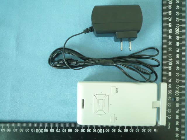
VQXAEC707C
Jul 08, 2010Digital Wireless TV receiver
Equipment Class
DXX - Part 15 Low Power Communication Device Transmitter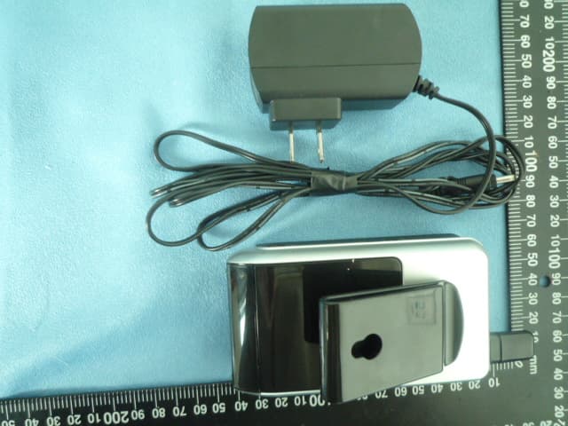
VQXAEC711C
Jul 08, 2010Wireless Handheld Screen Receiver
Equipment Class
DXX - Part 15 Low Power Communication Device Transmitter
VQXAEC9331CU-8
Jun 08, 2010THE INTELLIGENT MOTION SENSOR TRACKING LIGHT-Light
Equipment Class
DXX - Part 15 Low Power Communication Device Transmitter