VQXAEC707CDigital Wireless TV receiver
Aurum Electronics Corp.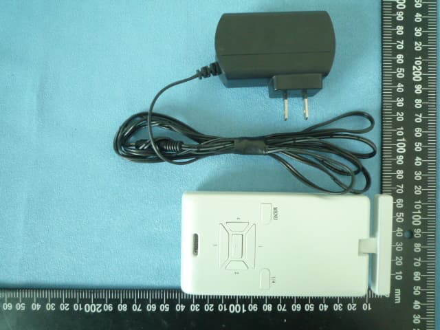
Click to zoom
Application Details
- Equipment Class
- DXX - Part 15 Low Power Communication Device Transmitter
- Date of Grant
- Jul 08, 2010
- Application Purpose
- Original Equipment
- Date of Application
- Jul 08, 2010
- Equipment Note
- Digital Wireless TV receiver
- Frequency Range
- 2402.00000000 - 2480.00000000
- Company
- Aurum Electronics Corp.
- Country
- Taiwan
Documents & Files
Document Text
Text extracted from the exhibit documents filed with the FCC. Open a document above to read the original.
Users Manual
AEC-707C DIGITAL WIRELESS TV RECEIVER Noted the receiver will combine with digital camera fitting to use; Please Read all instructions before proceeding with the installation I. OVERVIEW II. ASSEMBLY INSTRUCTIONS 1. Connect the receiver to a Monitor/TV with AV cable. (yellow for video and red for audio, but audio is not available here) 2. Connect the adapter to the receiver. (DC 6V 0.5A). 3. Push the power switch to ON position and the LED indicator lights up MENU Button OK Button Channel Button Buzzer Antenna Video Output Power Socket View Button (1/4) (Single/Quad) LED indicator Power switch 4.Power on the Monitor/TV and select AV mode. 5. Set the channel of the receiver to the same as that of camera fitting by pressing the channel button continuously and then you can see the camera image displayed on the connected Monitor/TV. This receiver can be paired with up to four camera fitting. - Press “MENU Button” then press Channel Button to select “MONITOR” and press “OK button”. - Press “Channel Button” to select ”Pair Cam” and then press “OK button”. - There is ”1 2 3 4” shown on the TV, to select which number of channel you want to set up this fitting. Within 10 seconds, press “Channel Button” to select the number of the channel you want then press ”OK button”. Within 10 seconds, press the “Dip Switch” on the fitting and when you see detecting image displayed on the TV, it means the channel setting is completed. If it shows “No Connection”, repeat these steps again. - For other three different fittings, repeat the above same steps to set up the different channel. Press ”View Button” for Quad View condition to see a split screen view of all channels. NOTE: 1. To set each channel, TV must be in “Single View”mode. 2. Before setting the channel between the fitting and receiver, first press “Push-Button” switch on the bottom of the fitting, the stepper motor will stop working (the RED LED will keep flashing) in order to keep “Dip Switch” on the fitting not moving and can be easily pressed when setting up the channel later. 6. Adjust the brightness, contrast and color of the monitor/TV for the perfect effect. III. OPERATION When Camera Fitting is in operation, this TV receiver is triggered giving images immediately, the camera operates all the time whilst the power on. The unobstructed transmission effective range is about 80 meters, but actual transmission range may vary according to weather, location, interference and building. One wireless receiver can receive 4 camera images. To view images from a different channel, press the receiver’s corresponding channel button, and an image will be displayed on the Monitor/TV. Push-button OPERATION OF TV RECEIVER 1. LCD image display: push view button「1/4」for image display -Single View: single CAMERA view (initial image<original default>) display image from one camera at one time -Quad View : 4 split view (able to connect 4 CAMERAS and display 4 images on screen at the same time) ☆When SENSOR is triggered, the monitor will sound ”BEEP” (“BEEP” is set “ON” condition) No. 1 sensor light detects motions, sound ”BEEP” once No. 2 sensor light detects motions , sound ”BEEP-BEEP” twice No. 3 sensor light detects motions, sound ”BEEP-BEEP-BEEP”3 times No. 4 sensor light detects motions, sound ”BEEP-BEEP-BEEP-BEEP” 4 times BEEP will sound continuously for 20 times and stops if there is no fur☆ther detection. During 20 times of BEEP if this unit detects any motions, it will recount for 20 times. ☆ Push any of the buttons to stop ”BEEP”. ☆When BEEP is set “OFF”, there will be no sound. ☆「View Mode」is set ”MENU”(manual) , the number of camera will flash under quad-view. 2. Function settings:push “MENU “ button to choose settings. -CAMERA: Cam1 EV:-2.0~+2.0 Cam2 EV:-2.0~+2.0 Cam3 EV:-2.0~+2.0 Cam4 EV:-2.0~+2.0 Set the brightness of CAMERA. Standard value is 0, turn the knob to ”-“ side to reduce the brightness, turn the knob to ”+”side to increase the brightness. Before attempting any setting, please power sensor light. For multiple cameras, the brightness of each CAMERA may be different, please adjust the brightness to preferred value. (Every adjustment value is 0.5. Original default is 0.) Freq:50 / 60 Hz Version:software program version Reset:Ye s / N o Back to original default. IMPORTANT This is only for connecting 1 CAMERA. For connecting several CAMERAS, make sure to return to quad-view after finishing setting in single view. -MONITOR: Beep:ON /OFF(original default ON) When SENSOR detects motions, monitor will beep. Beep Vol:High /Low(original default High) Volume adjustment for beep OSD Disp:ON /OFF Date and antenna icon display set View Mode:AUTO /MENU( original default AUTO) Single view and quad-view setting (AUTO/MENU): Under AUTO mode, single view will return to quad-view automatically 20 seconds later;under MENU mode, please switch from single view to quad-view by manual. Under MENU mode, if switch to single view, there will no display on the screen if other sensor lights detect motions. Scan time:OFF /5SEC/10SEC/15SEC (original default OFF) Looping function, 4 CAMERAS display single view on the screen in order. Pair Cam:1/2/3/4 Register CAMERA ID。(up to 4 CAMERAS) Version:software program version Reset:YES/NO Back to original default. -Other:Date/Time:set time and date IMPORTANT Before registering ID, please push the bottom button to stop sensor light turning.
Cover Letter(s)
FCC Authorization Letter Number: CF304 Version: V01 Date: 01-02-2010 We, (the approval holder) Company name Aurum Electronics Corp. Addresss NO.160.Dayong Rd. YongKang City.Tainan Hsien.710, Taiwan City Yongkang Country china declare that the following representative (agent): Name (person) Company name Asia Institute Technology (Dongguan) Limited Addresss No.6 Binhe Road, Tianxin Village, Huangjiang, City Dongguan, Guangdong Country China is hereby authorized to apply the following equipment for certification on our behalf: Product Description Digital Wireless TV receiver Type or Model(s) AEC-707C Tradename or Brand(s) We also authorize Teleconformity, Mr. M. Koop, (address: Rietven 31, 7534NH Enschede, Netherlands) to process this application. Attestation: City and Country: Date: Name: (this must be a person) Function: Signature: (or official company stamp) Yongkang 2010.06.29 Eugene.Huang Manager
External Photos
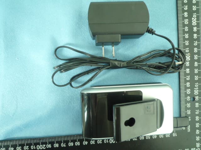
Report No.: F-R1006010 Page 23 of 29 Rev:None Asia Institute Technology (Dongguan) Limited No,6.Binhe Road, Tianxin Village, Huangjiang, Dongguan, Guangdong, China. 7 APPENDIX-Photographs of EUT Constructional Details Photo 1 Photo 2 Report No.: F-R1006010 Page 24 of 29 Rev:None Asia Institute Technology (Dongguan) Limited No,6.Binhe Road, Tianxin Village, Huangjiang, Dongguan, Guangdong, China. Photo 3 Photo 4
Test Setup Photos
Report No.: F-R1006010 Page 21 of 28 Rev:None Asia Institute Technology (Dongguan) Limited No,6.Binhe Road, Tianxin Village, Huangjiang, Dongguan, Guangdong, China. 6.6 Test Setup photograph Conduction(0.15-30MHz) Radiation(30MHz-1GHz) Report No.: F-R1006010 Page 22 of 28 Rev:None Asia Institute Technology (Dongguan) Limited No,6.Binhe Road, Tianxin Village, Huangjiang, Dongguan, Guangdong, China. Radiation(1GHz-25GHz)
Contact Information
Applicant
Eugene Huang(Vice General Manager)
Test Firm
Dongguan Yaxu (AiT) Technology LimitedJackie Deng
Technical Specifications
| # | Rule Parts | Frequency Range | Power Output |
|---|---|---|---|
| 1 | 15C | 2.40 GHz - 2.48 GHz | - |
Other Applications from Aurum Electronics Corp.
VQXAEC711C
Jul 08, 2010Wireless Handheld Screen Receiver
Equipment Class
DXX - Part 15 Low Power Communication Device Transmitter
VQXAEC9331CU-8
Jun 08, 2010THE INTELLIGENT MOTION SENSOR TRACKING LIGHT-Light
Equipment Class
DXX - Part 15 Low Power Communication Device Transmitter
VQX-939ASD-MIC
Dec 11, 2007Smart Guard Halogen Light
Equipment Class
DSC - Part 15 Security/Remote Control Transmitter