VQXAEC9331CU-8THE INTELLIGENT MOTION SENSOR TRACKING LIGHT-Light
Aurum Electronics Corp.
Click to zoom
Application Details
- Equipment Class
- DXX - Part 15 Low Power Communication Device Transmitter
- Date of Grant
- Jun 08, 2010
- Application Purpose
- Original Equipment
- Date of Application
- Jun 07, 2010
- Equipment Note
- THE INTELLIGENT MOTION SENSOR TRACKING LIGHT-Light
- Frequency Range
- 2402.00000000 - 2480.00000000
- Company
- Aurum Electronics Corp.
- Country
- Taiwan
Documents & Files
Document Text
Text extracted from the exhibit documents filed with the FCC. Open a document above to read the original.
Users Manual
THE INTELLIGENT MOTION SENSOR TRACKING LIGHT INSTALLATION INSTRUCTIONS Read all instructions before proceeding with the installation OVERVIEW OF AEC-9331CU-SP8 IMPORTANT: THE INTALLATION OF THIS FITTING MUST BE DONE BY A QUALIFIED ELECTRICIAN. This fitting must be earthed. Do not mount the luminaire against inflammable surfaces. The motion detector will not operate correctly if it is installed: ( ) Near the outlet of a central heating boiler I ( ) Near air conditioning plant II ( ) Pointing directly at moving vehicles III ( ) Within sight of reflection from moving water IV ( ) Where other lamps could shine onto the detectorV NOTE: * This highly responsive unit may occasionally activate due to rapid environmental changes. Allow for approximately 30 seconds warm-up time before the sensor resumes normal activity. * Please make sure the voltage and polarity are correct before connection. Incorrect voltage may cause electric shock. If you are not sure, please contact your retailer. * Do Not remove the tape until your finish the installation. If the tape comes off the light, please replace it or hold the light head to avoid swiveling and damage the product. MOUNTING THE FITTING To ensure correct operation of the sensor, mount the luminaire that traffic passes across the detector. WARNING ! ! ! BEFORE ATTEMPTING ANY INSTALLATION OR MAINTENANCE, ENSURE THAT THE ELECTRICAL SUPPLY IS SWITCHED OFF AND THE CIRCUIT FUSES REMOVED OR THE CIRCUIT BREAKER IS IN THE “OFF”POSITION. TOP GOOD SENSITIVITYLESS SETTING THE LIGHT UP TIME & SENSITIVITY Remove the back mounting box from the fixture by unscrewing the screw at the bottom. Set the Light up time & Sensitivity you preferred 1:Light activation time (OFF:30 seconds/ON:60 seconds) 2:Light Sensitivity (OFF:5m/ON:10m) Re-fit the back mounting box and tighten the screw. INSTALLATION AND WIRING INSTRUCTIONS Remove the existing light fixture. Install crossbar lower plate as shown with two screws. Do not completely tighten central screws. Remove the base bracket from the light fixture. Align base bracket and a crossbar upper plate and secure it with two screws. Make sure the base bracket is straight. Tighten two central and two base bracket screws. Do not use excessive force. The recommended installation height of this light fixture is between 6.5 -10 ft. NOTE: DO NOT REMOVE THE TAPE UNTIL YOU FINISH THE INSTALLATION. IF THE TAPE COMES OFF THE LIGHT, PLEASE REPLACE IT OR HOLD THE LIGHT HEAD TO AVOID SWIVELING AND DAMAGE TO THE PRODUCT. 1. Attach the crossbar to junction box and fix by screw A. 2. Connect the black wire (live wire) from the AC power cord to the single black wire coming from Sensor Tracking Light using one of the supplied wire nuts. 3. Connect the white wire from the AC power cord to the white wire coming from Sensor Tracking Light using one of the supplied wire nuts. 4. Connect the green/yellow wire from the AC power cord to the green/yellow wire coming from Sensor Tracking Light using one of the supplied wire nuts. 5. Make sure the polarity is correct. 6. Attach the unit to the crossbar and fix by screw B and screw C. FUNCTION This light is equipped with 3 motion sensors: zone 1 covers 60 degree, zone 2 covers 100 degrees and zone 3 covers 60 degrees. 220 degrees (maximum) in total for 3 zones. The light will switch on for 30 /60 seconds and off automatically when heat/ movement is detected. The factory default: the mode is「Nighttime Mode」for light works at night, camera works all day. To change the mode to all day mode, push the button at the bottom of the housing and the hidden LED indicator will turn off at this mode. The light will be on at 30 /60 seconds when detecting any movement at all day. Push-button for programmable functions: - All Day Mode: light and camera work all day (the hidden LED indicator will turn on in RED) - Nighttime Mode: light works at night, camera works all day (the hidden LED indicator will turn off) Reset function: If the stepper motor of tracking light works abnormal, the hidden LED indicator will flash in red and the light will stop turning automatically. In All Day Mode, the red LED will flash for 3 times in 5 seconds and off for 5 seconds; in “Nighttime Mode”, the red light will flash in regular pattern. Please simply switch off and on the main power to resume the tracking light. Below are the possible abnormal situations. - External force: the light head is blocked by objects or is blown by strong wind and is unable to turn properly, the hidden LED will flash in red to signal users the abnormal situation. Stepper motor: when stepper motor is going to be out of its lifetime or is damaged, the hidden LED will flash in red to signal users the abnormal situation. Please switch off and on the main power, the tracking light now may or may not resume its operation. If the stepper motor stops working, the fitting becomes a regular motion sensor security light. ZONE 1 ZONE 2 ZONE 3 TOTAL DETECTION RANGE OPERATION 1. Turn on the wall switch to activate the fitting, the fitting is now under Nighttime mode: light works at night and camera works all day. You will be able to view what the camera sees with the handheld LCD Monitor. The camera operates 24 hours a day and is not controlled by the PIR sensors. NOTE: Allow for approximately 30 seconds warm-up time before the sensor resumes normal activity. 2. To test, walk through the sensor’s detection area. 3. Movement will activate the sensor and turn the light on, the light and camera will turn to face to the detected zone. the light will operate for the programmed time(30/60seconds). You will be able to see what or who has caused the PIR to activate with the handheld LCD Monitor. 4. After the PIR is activated, keep out of detection area and the light will switch off automatically after the programmed time (30/60 seconds). The light will be activated again when detecting any further movement. If there is continuing movement in the detection zone, the li…
Text truncated - open the document above for the full version.
External Photos
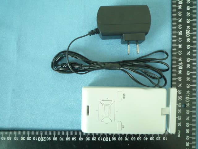
Report No.: F-R0100603 Page 23 of 31 Rev:None Asia Institute Technology (Dongguan) Limited No,6.Binhe Road, Tianxin Village, Huangjiang, Dongguan, Guangdong, China. 7 APPENDIX-Photographs of EUT Constructional Details Photo 1 Photo 2
Internal Photos
Report No.: F-R0100603 Page 24 of 31 Rev:None Asia Institute Technology (Dongguan) Limited No,6.Binhe Road, Tianxin Village, Huangjiang, Dongguan, Guangdong, China. Photo 3 Photo 4 Report No.: F-R0100603 Page 25 of 31 Rev:None Asia Institute Technology (Dongguan) Limited No,6.Binhe Road, Tianxin Village, Huangjiang, Dongguan, Guangdong, China. Photo 5 Photo 6 Report No.: F-R0100603 Page 26 of 31 Rev:None Asia Institute Technology (Dongguan) Limited No,6.Binhe Road, Tianxin Village, Huangjiang, Dongguan, Guangdong, China. Photo 7 Photo 8 Report No.: F-R0100603 Page 27 of 31 Rev:None Asia Institute Technology (Dongguan) Limited No,6.Binhe Road, Tianxin Village, Huangjiang, Dongguan, Guangdong, China. Photo 9 Photo 10 Report No.: F-R0100603 Page 28 of 31 Rev:None Asia Institute Technology (Dongguan) Limited No,6.Binhe Road, Tianxin Village, Huangjiang, Dongguan, Guangdong, China. Photo 11 Photo 12 Report No.: F-R0100603 Page 29 of 31 Rev:None Asia Institute Technology (Dongguan) Limited No,6.Binhe Road, Tianxin Village, Huangjiang, Dongguan, Guangdong, China. Photo 13 Photo 14 Report No.: F-R0100603 Page 30 of 31 Rev:None Asia Institute Technology (Dongguan) Limited No,6.Binhe Road, Tianxin Village, Huangjiang, Dongguan, Guangdong, China. Photo 15 Photo 16 Photo 17 Report No.: F-R0100603 Page 31 of 31 Rev:None Asia Institute Technology (Dongguan) Limited No,6.Binhe Road, Tianxin Village, Huangjiang, Dongguan, Guangdong, China.
Test Report
Report No.: F-R0100603 Page 1 of 31 Rev:None Asia Institute Technology (Dongguan) Limited No,6.Binhe Road, Tianxin Village, Huangjiang, Dongguan, Guangdong, China. FCC Test Report Client Information: Applicant: Aurum Electronics Corp. Applicant add.: No.160, Dayong Rd., Tainan Hsien Yongkang City, Taiwan EUT Information: EUT Name: THE INTELLIGENT MOTION SENSOR TRACKING LIGHT Model No.: AEC9331CU-SP8 Brand Name: N/A FCC ID: VQX-AEC9331CU-8 IC ID: 7507A-AEC9331CU-8 Prepared By: Asia Institute Technology (Dongguan) Limited Add. : No.6 Binhe Road, Tianxin Village, Huangjiang, Dongguan, Guangdong, China. Date of Receipt: May 20, 2010 Date of Test: May. 21 ~ 28, 2010 Date of Issue: Jun. 1, 2010 Test Result: Pass Test procedure used: ANSI C63.4-2003 This device described above has been tested by Asia Institute Technology (Dongguan) Limited, and the test results show that the equipment under test (EUT) is in compliance with the FCC requirements. And it is applicable only to the tested sample identified in the report. *This test report must not be used by the client to claim product endorsement by any agency of the U.S. government. Reviewed by: Approved by: Test director Technical director Report No.: F-R0100603 Page 2 of 31 Rev:None Asia Institute Technology (Dongguan) Limited No,6.Binhe Road, Tianxin Village, Huangjiang, Dongguan, Guangdong, China. 1 Contents Page COVER PAGE 1 CONTENTS ...........................................................................................................................................................2 2 TEST SUMMARY ..................................................................................................................................................3 2.1 COMPLIANCE WITH FCC PART 15 SUBPART C ...................................................................................................3 2.2 MEASUREMENT UNCERTAINTY............................................................................................................................3 3 TEST FACILITY.....................................................................................................................................................4 3.1 DEVIATION FROM STANDARD...............................................................................................................................4 3.2 ABNORMALITIES FROM STANDARD CONDITIONS....................................................................................................4 4 GENERAL INFORMATION ...................................................................................................................................5 4.1 GENERAL DESCRIPTION OF EUT ........................................................................................................................5 4.2 DESCRIPTION OF TEST CONDITIONS....................................................................................................................6 4.3 PERIPHERAL LIST...............................................................................................................................................7 5 EQUIPMENTS LIST FOR ALL TEST ITEMS .......................................................................................................7 6 TEST RESULT.......................................................................................................................................................8 6.1 ANTENNA REQUIREMENT....................................................................................................................................8 6.1.1 Standard requirement ..............................................................................................................................8 6.1.2 EUT Antenna ...........................................................................................................................................8 6.2 CONDUCTION EMISSIONS MEASUREMENT...........................................................................................................9 6.2.1 limit...........................................................................................................................................................9 6.2.2 Test procedure.........................................................................................................................................9 6.2.3 Test result ..............................................................................................................................................10 6.3 RADIATED EMISSIONS MEASUREMENT..............................................................................................................12 6.3.1 Limit........................................................................................................................................................12 6.3.2 Test procedure.......................................................................................................................................12 6.3.3 Test Result .............................................................................................................................................13 6.4 BAND EDGES...................................................................................................................................................17 6.4.1 Limit........................................................................................................................................................17 6.4.2 Test procedure.......................................................................................................................................17 6.4.3 Test Result .............................................................................................................................................17 6.5 OCCUPIED BANDWIDTH....................................................................................................................................18 6.5.1 Limit...........................…
Text truncated - open the document above for the full version.
Test Setup Photos
Report No.: F-R0100603 Page 22 of 31 Rev:None Asia Institute Technology (Dongguan) Limited No,6.Binhe Road, Tianxin Village, Huangjiang, Dongguan, Guangdong, China. Test Setup photograph Radiation(30MHz-1GHz) Radiation(1GHz-25GHz)
Contact Information
Applicant
Eugene Huang(Vice General Manager)
Technical Contact
Asia Institute Technology limitedBovey
[email protected]+86.769.8202.0499
No.6, Bin-He Roan Tian-Xin · DongGuan · China
Test Firm
Dongguan Yaxu (AiT) Technology LimitedJackie Deng
Technical Specifications
| # | Rule Parts | Frequency Range | Power Output |
|---|---|---|---|
| 1 | 15C | 2.40 GHz - 2.48 GHz | - |
Other Applications from Aurum Electronics Corp.
VQXAEC707C
Jul 08, 2010Digital Wireless TV receiver
Equipment Class
DXX - Part 15 Low Power Communication Device Transmitter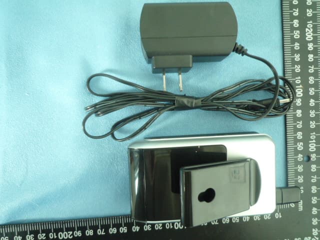
VQXAEC711C
Jul 08, 2010Wireless Handheld Screen Receiver
Equipment Class
DXX - Part 15 Low Power Communication Device Transmitter
VQX-939ASD-MIC
Dec 11, 2007Smart Guard Halogen Light
Equipment Class
DSC - Part 15 Security/Remote Control Transmitter