VR3EA100103EA-100102 Hybrid Rim & EA-100103 Hybrid Mortise
Medeco Security Locks, Inc.
Click to zoom
Application Details
- Equipment Class
- DCD - Part 15 Low Power Transmitter Below 1705 kHz
- Date of Grant
- Feb 18, 2008
- Application Purpose
- Original Equipment
- Date of Application
- Feb 05, 2008
- Equipment Note
- EA-100102 Hybrid Rim & EA-100103 Hybrid Mortise
- Frequency Range
- 0.12500000 - 0.12500000
- Company
- Medeco Security Locks, Inc.
- Country
- United States
Documents & Files
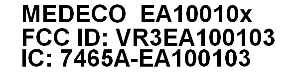
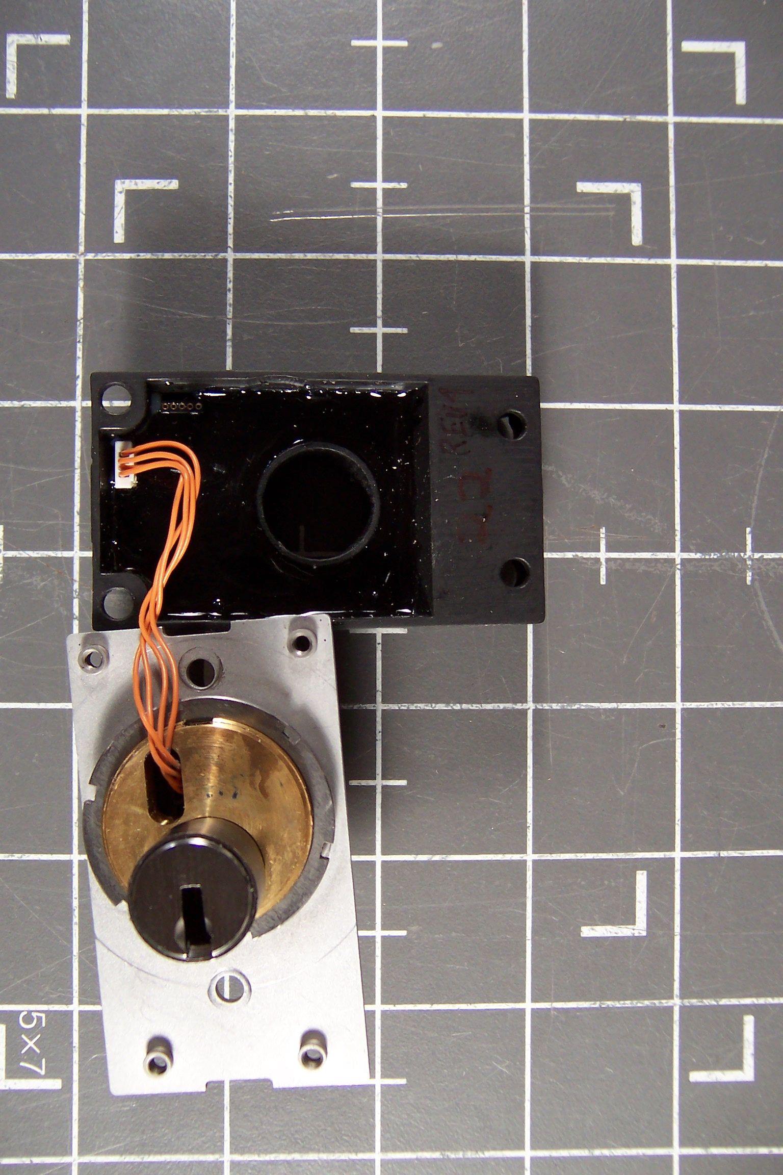
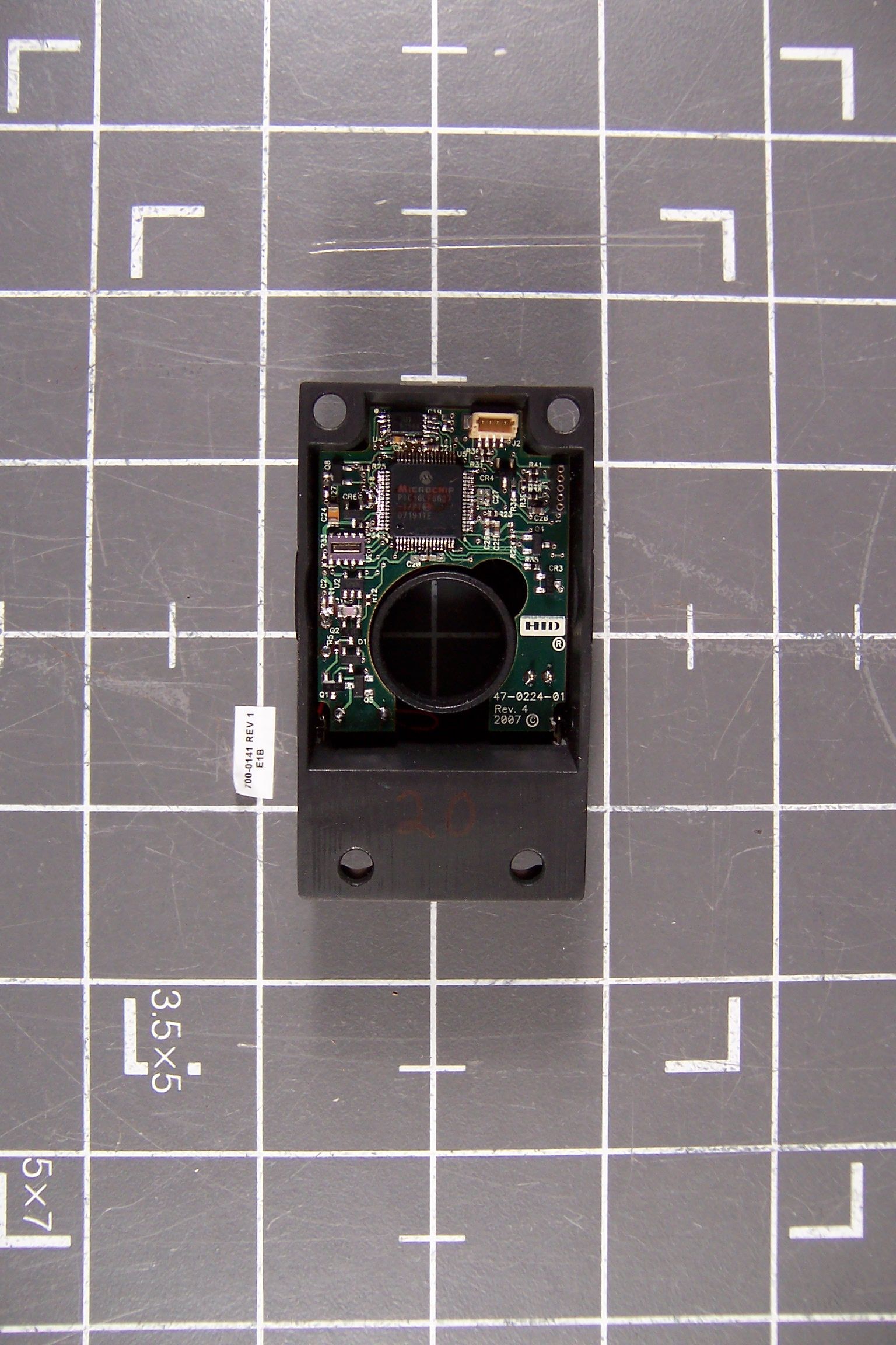
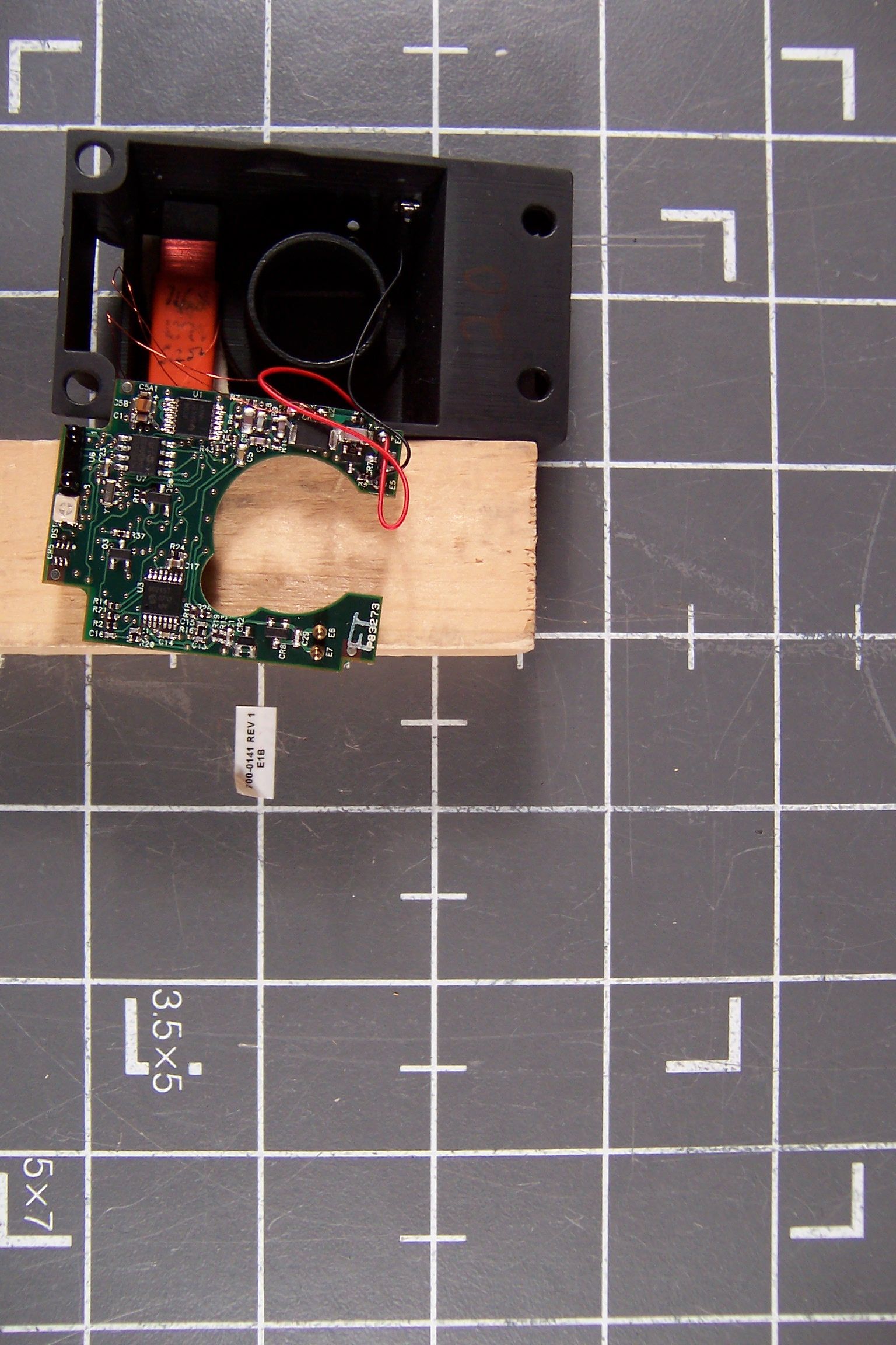
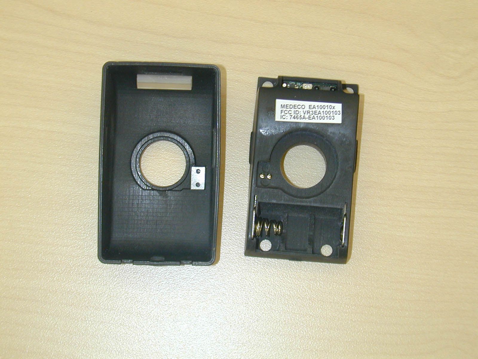
Document Text
Text extracted from the exhibit documents filed with the FCC. Open a document above to read the original.
Users Manual
An ASSA ABLOY Group Company Hybrid e-Cylinder User Guide Version 2.0 Part Number LT-06047 Issue Date: January 28, 2008 Medeco Hybrid User Guide 2 of 16 Table of Contents 1 Introduction ....................................................................................................3 2 Design Description – Hybrid Main Control Unit (MCU) ..................................4 3 Design Description – Hybrid Lock Cylinder (LCU) .........................................5 4 Functional Description ...................................................................................5 4.1 IR Communications ................................................................................6 4.2 Master Key .............................................................................................6 4.3 User Keys ...............................................................................................6 4.4 Non Volatile Memory Configuration ........................................................6 4.5 User Groups ...........................................................................................6 4.6 Key Validation Dates ..............................................................................7 4.7 Group Codes..........................................................................................7 4.8 Daily Time Zone Schedules....................................................................7 5 Access Control Operation ..............................................................................7 5.1 LED Annunciations .................................................................................7 5.2 Low Battery Alarm ..................................................................................8 5.3 Tamper Alarm .........................................................................................9 6 Installation Procedures – Mortise Application ................................................9 6.1 What is required: ....................................................................................9 6.2 Installation procedure when MCU is programmed at the door................9 6.3 Procedure for programming an MCU prior to installation at door..........12 6.4 Installation procedure when MCU is programmed in advance..............13 7 Notifications .................................................................................................16 Medeco Hybrid User Guide 3 of 16 1 Introduction The Medeco/HID 125 kHz E-Cylinder is a battery operated RFID enabled electromechanical lock (Figure 1). The unit as a whole is designed to be self-contained (no external wire or communication connections) and operates to secure a door or entry portal. Access is granted on the presentation of an authorized key (mechanical key and integrated transponder) to a master control unit (Hybrid reader) which in turn, through secure communication, issues command for a lock control unit (Lock Cylinder) to actuate a locking mechanism of a cylinder installed in said door or entry portal. Figure 1: Medeco/HID 125 kHz E-Cylinder (nested components) The unit as a whole is generally comprised of five main subsystems; 1) the plastic internal/external housings, 2) the electronic HW/FW circuit card assembly contained in the internal/external housings, 3) mechanical lock cylinder engaged to door or entry portal hardware, 4) an electronic HW/FW circuit card module contained in the mechanical lock cylinder, and 5) an access control credential (not shown) as illustrated in Figure 2. Medeco Hybrid User Guide 4 of 16 2 Design Description – Hybrid Main Control Unit (MCU) The Hybrid MCU consists of the following components illustrated in Figures 2 & 3. These items include: Internal Housing with electronic module - MCU External Housing cover Rubber Insert LED Lens Anti-tamper Contact Optional Spacer (thin) Optional Spacer (thick) Figure 2: The primary subsystems comprising the Medeco/HID 125 kHz E-Cylinder. Figure 3: 3-D models of the components comprising the Medeco/HID 125kHz E-Cylinder Hybrid Housing Medeco Hybrid User Guide 5 of 16 3 Design Description – Hybrid Lock Cylinder (LCU) The Hybrid lock cylinder consists of the following components illustrated in Figure 4. These items include: Lock Control Unit (LCU) – Including lock cylinder & electronics module Lock CAM – specific to lock hardware type Interface Cable – Hard wired to electronics module Back plate Locking Ring Figure 4: 3-D models of the components comprising the Medeco/HID 125kHz E-Cylinder lock cylinder 4 Functional Description The Medeco Hybrid MCU is a stand-alone prox reader that maintains a local database of key and transaction information. Updates of valid key ID numbers and communication of transaction information is performed using an Infrared Communications interface. Other features of the cylinder include: • 32kBytes of non-volatile memory providing a flexible combination of key ID’s and transaction history. • Programmable via an IR interface enabled by a “Master” key. Locking Ring Back Plate Lock Cylinder (LCU) Lock CAM Interface Cable Medeco Hybrid User Guide 6 of 16 • 3-level low battery alarm (alarm condition may be reset using a Master key or using the IR interface) • Access Control system for controlling access based on user groups, valid entry times/dates. • Tamper monitoring feature with temporary reader disable 4.1 IR Communications The Hybrid MCU contains an IR communications port that allows programming of the unit with user keys, schedules, holidays etc. as well providing for the transfer of audit transaction data from the Hybrid to a PDA device. The IR communications are initiated by the presentation of the Master Key. 4.2 Master Key The Master key is used to initiate IR communications with the Hybrid reader and to reset it in certain alarm conditions, but will not open the lock. The Master key is always the first key in the database. The master key may be any (4-byte) number. Its parameters default to Group = 0, Start date …
Text truncated - open the document above for the full version.
Users Manual
12/04/07 Revision 1.0 1 of 6 Medeco HYBRID eCylinder Installation Procedures – Mortise Application 1. What is required: Hybrid cylinder kit Hybrid Cylinder (LCU) with proper cam MCU reader unit MCU outer cover MCU spacers Base plate Lock Ring MCU mounting screws Battery User key with correct mechanical keyway and cut Hybrid 125KHz Prox key head PDA programming device Programmed from the Hybrid Manager software Including access rights for the User Key The functionality to set the MCU clock Hybrid Manager Software 2. Installation procedure when MCU is programmed at the door 2.1 Remove mechanical cylinder from lockset. (if applicable) 2.2 Verify proper cam on Hybrid cylinder for lockset. 2.3 Rotate cam on back of Hybrid cylinder to home (locked) position – This removes the cylinder from the shipping (unlocked) position and mechanically “arms” the Hybrid cylinder. A properly bitted key must now be used to operate the lock cylinder. 2.4 Install (screw) the Hybrid cylinder into the lockset. Check for operation with the lockset using the User key to operate the cylinder mechanically. Adjust the cylinder as necessary for door thickness, cam engagement, etc. 2.5 When cylinder adjustments are complete, tighten set screw in lockset to secure cylinder in place. 12/04/07 Revision 1.0 2 of 6 2.6 Install base plate and lock ring to secure lock cylinder to door. Install spacers as required for thin door applications. 2.7 Place cylinder in locked position and remove the User key. User key is no longer needed until Hybrid unit is programmed. 2.8 Ensure the battery is removed from the MCU unit. 2.9 Connect the cable from the cylinder to the back of the MCU unit. 2.10 Locate and install the MCU onto the base plate using the four mounting screws. Care must be taken to ensure the interconnect cable is routed properly behind MCU and is not damaged. 2.11 Install the battery into the MCU MCU will power up and flash the LED red, yellow, green - one sequence. The MCU will power up in tamper condition. The LCU will power up and “arm” the electronic blocking mechanism (mechanical key alone will no longer operate lock) 2.12 Install the MCU outer cover The tamper switch will be reset The MCU will start to search (ping) for a credential At this point: MCU is still in tamper mode MCU has no master credential identified and stored MCU and LCU are not registered to each other MCU and LCU are not authorized with each other MCU clock is not set MCU is not programmed with a key list, schedules, etc. 2.13 Present the Master Credential (Prox Card) to the MCU – The master credential should be the same used for all other Hybrid locks in this installation (customer site) MCU reads and stores the Prox Card as its master credential – It remains the master credential unless reprogrammed later. The LED will flash green for 3 cycles to indicate the master credential was accepted. MCU resets the tamper condition 12/04/07 Revision 1.0 3 of 6 MCU registers with the LCU MCU establishes authorization with the LCU MCU turns on the IR communications port. The MCU will flash the LED red when the IR communications session times out. 2.14 Program the MCU with the PDA – PDA should be loaded with key list (including User key used for installation) 2.15 Present the PDA to the MCU – IR port on PDA must be active 2.16 Present the master credential to the MCU The MCU reads the master credential, flashes the LED green and turns on the IR communications port The PDA communicates with the MCU via the IR link and uploads a key list and schedules etc. into the MCU The PDA sets the clock in the MCU The MCU will flash the LED green at the completion of the communications session. (The MCU will flash the LED red if the IR communications session times out prior to completing the communications session.) The Hybrid lock is now functional and ready for use 2.17 Present the User key to test the function of Hybrid unit with the lockset 3. Procedure for programming an MCU prior to installation at door. Note: LCU is not connected or utilized in the advance programming of the MCU. If the LCU is connected to the MCU during this process the two components will register to each other and require the installer to keep the MCU and LCU together as a matched pair until installed onto the door. 3.1 Install battery into MCU MCU will power up and flash the LED red, yellow, green - one sequence. The MCU will power up in tamper condition. 12/04/07 Revision 1.0 4 of 6 3.2 Install the MCU outer cover The tamper switch will be reset The MCU will start to search (ping) for a credential At this point: MCU is still in tamper mode MCU has no master credential identified and stored MCU and LCU are not registered to each other – No LCU connected MCU and LCU are not authorized with each other – No LCU connected MCU clock is not set MCU is not programmed with a key list, schedules, etc. 3.3 Present the Master Credential (Prox Card) to the MCU – The master credential should be the same used for all other Hybrid locks in this installation (customer site) MCU reads and stores the Prox Card as its master credential – It remains the master credential unless reprogrammed later. The MCU flashes the LED green, red, green to indicate the master credential was accepted but no LCU was found. MCU resets the tamper condition MCU turns on the IR communications port - The MCU will flash the LED red when the IR communications session times out. 3.4 Program the MCU with the PDA – PDA should be loaded with key list (including User key used for installation) 3.5 Present the PDA to the MCU – IR port on PDA must be active 3.6 Present the master credential to the MCU MCU reads the master credential and flashes LED green, red, green to indicate (Master credential valid, No LCU connected, IR port turned on) The PDA communicates with the MCU via the IR link and uploads a key list and schedules etc. into the MCU The PDA sets the clock in the MCU 12/04/07 Revision 1.0 5 of 6 The MCU will flash LED green at the comp…
Text truncated - open the document above for the full version.
Cover Letter(s)
An ASSA ABLOY Group Company 1 of1 November 16 th, 2007 Federal Communications Commission 7435 Oakland Mills Road Columbia, MD 21046 Gentlemen: This letter is to comply with Section 0.457 and 0.459 pertaining to confidential material. Medeco Security Locks, Inc. would like the following documents regarding this submission for FCC ID: VR3EA100103 to be kept confidential. 1. All Schematics 2. All block diagrams 3. Description of the Hybrid Mortise Lock, circuit functions, how the device operates, ground system and antenna The above material contains trade secrets or technical data, which would customarily be guarded from competitors. We do not want these documents to be accessible to the general public. Sincerely, Doug Trent Director Product Development Medeco Security Locks 540-380-1729 [email protected]
Cover Letter(s)
An ASSA ABLOY Group Company 1 of1 November 16 th, 2007 To whom it may concern: We the undersigned, hereby authorize CKC Laboratories, Inc., to act on our behalf in all manners relating to application for equipment authorization, including signing of all documents relating to these matters. Any and all acts carried out by CKC Laboratories, Inc., on our behalf shall have the same affect as acts of our own. This authorization is valid until further written notice from Medeco Security Locks, Inc.. Sincerely, Doug Trent Director Product Development Medeco Security Locks 540-380-1729 [email protected]
Cover Letter(s)
CKC Certifications Se rvices - Confidential E08-000008-FCC EP04 8 of 11 Rev 10 Appendix A Non-Conformities for US Radio Equipment Authorization Non-Conformities FCC ID: VR3EA100103 (CKC CS Ref # E08-000008-FCC-01) The items listed below represent requests for information following review of this application for certification under United S tates (FCC) regulations. Further question may arise pending review of responses to these items. OK # Non-Conformity or Comment Submit ted Response Respondent / Date of Response x 1 The Equipment authorization indicated on page one of the circuit description referenced to Part 15.201 which is not consistent with the authorization sought after. Please provide revised circuit description with the appropriate references. CKC CS Management acknowledges that certification is sought pursuant to 15.201. N/A x 2 The schematic diagram indicated the pr esence of a 8MHz crystal, however this 8 MHz clock is missing from the block diagram. Please provide revised block diagram showing all oscillators in the device. Updated block diagram provided. CKC Labs 2/6/08 x 3 Page 10 and 11 of the listed TBD as the model number which is not consistent with the model number listed on the title page of the report and the application. Please provide revised data sheet with correct model number. Updated test report provided. CKC Labs 2/5/08 x 4 The internal photographs do not provide enough detail of the PCB and construction. Please provide legible inte rnal photographs of the top and bottom of the PCB, including the removal of shielding, in addition to showing identity of major frequency determining components in accordance with 2.1033. Updated exhibit provided with better resolution. CKC Labs 2/5/08 x 5 Necessary user manual statements are missing from the user manual. Please provide an updated users manual incorporating the statement required by 15.21 Updated manual provided. CKC Labs 2/5/08 x 6 The device incorporated digital control, IR transmit and receive capability, please provide an updated users manual incorporating the appropriate users manual statemen t in accordance with 15.105 CKC CS notes that equipment is not a computer peripheral. NA x 7 The label placement diagram does not clearly show whether the label is place at a visible location during the time of purchase. Please provide a revised label placement diagram clearly indicating the visibility of the label. Alternatively, a statement stating the label is placed in the battery compartment is sufficient fo r clarification purposes. Updated exhibit provided. CKC Labs 2/6/08 CKC Certifications Se rvices - Confidential E08-000008-FCC EP04 9 of 11 Rev 10 x 8 Please provide an updated label with labeling requirements in accordance with 15.19 Updated manual provided. CKC Labs 2/5/08 x 9 CKC CS understands that client wish to obtain modular approval for this equipment. Please provide a letter requesting modular approval in accordance with DA 00-1407. Device is a final product; does not qualify for MA – request rescinded. CKC Labs 2/6/08 The items indicated above must be submitted before processing can continue on the referenced application. Failure to provide t he requested information within 60 days may result in application dismissal pursuant to Section 2.917(c) and forfeiture of the filing fee pursuant to Se ction 1.1106. ---CKC CS SECTION--- ---Information below this line is for CKC CS Evaluators only--- CKCCS Note : Additions to non-conformities may be listed in a separate ta ble for convenience. When separated, the non-conformity referen ce serial number (NN) is incremented using in the following format reference # E08-000008-FCC-NN .
External Photos
Front Back Top Bottom Left Right
Test Report
Page 1 of 13 Report No.: FC07-090A ADDENDUM TO MEDECO SECURITY LOCKS, INC. TEST REPORT FC07-090 FOR THE EA-100103 HYBRID MORTISE FCC PART 15 SUBPART C SECTION 15.209 AND RSS-210 ISSUE 7 TESTING DATE OF ISSUE: JANUARY 15, 2008 PREPARED FOR: Medeco Security Locks, Inc. 3625 Allegheny Drive Salem, VA 24153-0330 PREPARED BY: Mary Ellen Clayton CKC Laboratories, Inc. 5046 Sierra Pines Drive Mariposa, CA 95338 W.O. No.: 87184Date of test: October 17, 2007 Report No.: FC07-090A This report contains a total of 13 pages and may be reproduced in full only. Partial reproduction may only be done with the written consent of CKC Laboratories, Inc. The results in this report apply only to the items tested, as identified herein. Page 2 of 13 Report No.: FC07-090A TABLE OF CONTENTS Administrative Information .............................................................................................3 Approvals .........................................................................................................................3 FCC to Canada Standard Correlation Matrix...................................................................4 Conditions During Testing...............................................................................................4 FCC 15.31(e) Voltage Variation......................................................................................5 FCC 15.31(m) Number Of Channels ...............................................................................5 FCC 15.33(a) Frequency Ranges Tested .........................................................................5 FCC 15.35 Analyzer Bandwidth Settings ........................................................................5 FCC 15.203 Antenna Requirements ................................................................................5 EUT Operating Frequency ...............................................................................................5 Temperature And Humidity During Testing....................................................................5 Equipment Under Test (EUT) Description ......................................................................6 Equipment Under Test .....................................................................................................6 Peripheral Devices ...........................................................................................................6 Report of Emissions Measurements.................................................................................7 Testing Parameters...............................................................................................7 FCC 15.209 Radiated Emissions .........................................................................9 RSS-210 99% Bandwidth ....................................................................................12 Page 3 of 13 Report No.: FC07-090A ADMINISTRATIVE INFORMATION DATE OF TEST: October 17, 2007DATE OF RECEIPT: October 17, 2007 REPRESENTATIVE: Frank de Vall MANUFACTURER: Medeco Security Locks, Inc. 3625 Allegheny Drive Salem, VA 24153-0330 TEST LOCATION: CKC Laboratories, Inc. 5046 Sierra Pines Drive Mariposa, CA 95338 TEST METHOD: ANSI C63.4 (2003), RSS-210 Issue 7 and RSS GEN Issue 2 PURPOSE OF TEST: Original Report: To perform the testing of the EA-100103 Hybrid Mortise with the requirements for FCC Part 15 Subpart C Section 15.209 and RSS-210 devices. Addendum A: To correct the model name on pages 10 and 11 with no new testing. APPROVALS Steve Behm, Director of Engineering Services TEST PERSONNEL: Mike Wilkinson, EMC Engineer/Lab Manager Page 4 of 13 Report No.: FC07-090A FCC TO CANADA STANDARD CORRELATION MATRIX Canadian Standard Canadian Section FCC Standard FCC SectionTest Description RSS GEN7.1.447CFR15.203Antenna Connector Requirements RSS GEN7.2.147CFR15.35(c)Pulsed Operation RSS GEN7.2.247CFR15.207AC Mains Conducted Emissions Requirement RSS 2102.147CFR15.215(c)Frequency Stability Recommendation RSS 2102.247CFR15.205Restricted Bands of Operation RSS 2102.647CFR15.209General Radiated Emissions Requirement RSS 210A2.647CFR15.209Fundamental RSS 210A2.6NANA±150kHz to ±450kHz Emissions Requirement RSS 210A2.647CFR15.225(d)Out of band emissions RSS 210A2.647CFR15.225(e)Carrier Stability IC 3082A-1784962Site File No. CONDITIONS DURING TESTING No modifications to the EUT were necessary during testing. Page 5 of 13 Report No.: FC07-090A FCC 15.31(e) Voltage Variations Not applicable to this device because it is battery powered and a fresh battery was used. FCC 15.31(m) Number Of Channels This device operates on a single channel. FCC 15.33(a) Frequency Ranges Tested 15.209 Radiated Emissions: 9 kHz – 1000 MHz FCC SECTION 15.35: ANALYZER BANDWIDTH SETTINGS PER FREQUENCY RANGE TESTBEGINNING FREQUENCYENDING FREQUENCYBANDWIDTH SETTING RADIATED EMISSIONS9 kHz150 kHz200 Hz RADIATED EMISSIONS150 kHz30 MHz9 kHz RADIATED EMISSIONS30 MHz1000 MHz120 kHz FCC 15.203 Antenna Requirements The antenna is an integral part of the EUT and is non-removable; therefore the EUT complies with Section 15.203 of the FCC rules. EUT Operating Frequency The EUT was operating at 125 kHz. Temperature And Humidity During Testing The temperature during testing was within +15°C and + 35°C. The relative humidity was between 20% and 75%. Page 6 of 13 Report No.: FC07-090A EQUIPMENT UNDER TEST (EUT) DESCRIPTION The customer declares the EUT tested by CKC Laboratories was representative of a production unit. The following model was tested by CKC Laboratories: Medeco Proximity Reader Door Lock Since the time of testing the manufacturer has chosen to use the following model name in its place. Any differences between the names does not affect their EMC characteristics and therefore meets the level of testing equivalent to the tested model name shown on the data sheets: EA-100103 Hybrid Mortise The manufacturer states that the following additional models are identical electrically to the one which was tested, or an…
Text truncated - open the document above for the full version.
Contact Information
Applicant
Douglas E. Trent(Dir. Product Development)
Technical Contact
CKC Laboratories, Inc.Mary Ellen Clayton
[email protected]209-966-5240
5046 Sierra Pines Dr. · Mariposa · United States
Test Firm
CKC Laboratories, Inc.Steve Behm
Technical Specifications
| # | Rule Parts | Frequency Range | Power Output |
|---|---|---|---|
| 1 | 15C | 0.125 MHz - 0.125 MHz | - |
Other Applications from Medeco Security Locks, Inc.

VR3-101501X
Jul 17, 2014Electronic Lock - Wireless IEEE802.15.4/2.4GHz and RFID/125kHz
Equipment Class
DXX - Part 15 Low Power Communication Device Transmitter
VR3-101500X
Dec 10, 2012Electronic lock � wireless IEEE 802.15.4/2.4GHz and RFID/13.56MHz
Equipment Class
DXX - Part 15 Low Power Communication Device Transmitter