VRVTR8000Tron AIS TR-8000
Jotron AS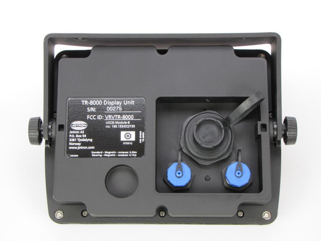
Click to zoom
Application Details
- Equipment Class
- AIS - Automatic Identification Systems
- Date of Grant
- Oct 25, 2012
- Application Purpose
- Original Equipment
- Date of Application
- Aug 27, 2012
- Equipment Note
- Tron AIS TR-8000
- Frequency Range
- 156.52500000 - 156.52500000
- Company
- Jotron AS
- Country
- Norway
Documents & Files
Document Text
Text extracted from the exhibit documents filed with the FCC. Open a document above to read the original.
Users Manual
www.jotron.com TECHNICAL MANUAL Tron AIS TR-8000 AIS Class A transponder TR-8000 Technical manual 1-2 EC Declaration of Conformity, available at www.jotron.com Table of Contents 1 Revision History.................................................................................................................... 1-4 2 SPECIFICATIONS ................................................................................................................... 2-5 2.1 Transponder unit ......................................................................................................................................... 2-5 2.1.1 Integrated GPS ......................................................................................................................................................... 2-5 2.1.2 TDMA Transmitter ................................................................................................................................................. 2-6 2.1.3 TDMA Receivers ...................................................................................................................................................... 2-6 2.1.4 DSC Receiver ............................................................................................................................................................. 2-7 2.2 Display unit: .................................................................................................................................................... 2-8 2.2.1 LCD Display with Touch ...................................................................................................................................... 2-8 2.3 Transmission intervals ................................................................................................................................. 2-9 2.4 Interfaces ...................................................................................................................................................... 2-10 2.5 Transmission Intervals ........................................................................................................................... 2-10 3 DATA TRANSMISSION .................................................................................................... 3-11 3.1 Data transmission...................................................................................................................................... 3-11 3.1.1 RS422 interface .....................................................................................................................................................3-11 3.1.2 RS232 interface .....................................................................................................................................................3-12 4 DESCRIPTION OF SENTENCE FORMAT ................................................................ 4-14 4.1 Input ................................................................................................................................................................ 4-15 4.1.1 ABM - Addressed Binary and safety related Message ..........................................................................4-15 4.1.2 ACA - AIS Regional Channel Assignment Message .................................................................................4-15 4.1.3 ACK - Acknowledge alarm ................................................................................................................................4-15 4.1.4 AIR - AIS Interrogation Request ....................................................................................................................4-16 4.1.5 AIQ - Query Sentence ..........................................................................................................................................4-16 4.1.6 BBM - Broadcast Binary Message ..................................................................................................................4-16 4.1.7 DTM Datum reference ........................................................................................................................................4-17 4.1.8 EPV – Command or report equipment property value ........................................................................4-17 4.1.9 GBS - GNSS satellite fault detection ..............................................................................................................4-19 4.1.10 GGA - Global positioning system (GPS) fix data ......................................................................................4-19 4.1.11 GLL - Geographic position - latitude/longitude ......................................................................................4-20 4.1.12 GNS - GNSS fix data ..............................................................................................................................................4-20 4.1.13 HBT Heart Beat ......................................................................................................................................................4-20 4.1.14 HDT - Heading true ..............................................................................................................................................4-21 4.1.15 LRF - Long Range Function ..............................................................................................................................4-21 4.1.16 LRI - Long-Range Interrogation .....................................................................................................................4-21 4.1.17 OSD Own ship data ..............................................................................................................................................4-22 4.1.18 RMC Recommended minimum specific GNSS data ...............................................................................4-22 4.1.19 ROT - Rate of turn .................................................................................…
Text truncated - open the document above for the full version.
Users Manual
www.jotron.com TECHNICAL MANUAL Tron AIS TR-8000 AIS Class A transponder TR-8000 Technical manual 1-2 EC Declaration of Conformity, available at www.jotron.com Table of Contents 1 Revision History.................................................................................................................... 1-4 2 SPECIFICATIONS ................................................................................................................... 2-5 2.1 Transponder unit ......................................................................................................................................... 2-5 2.1.1 Integrated GPS ......................................................................................................................................................... 2-5 2.1.2 TDMA Transmitter ................................................................................................................................................. 2-6 2.1.3 TDMA Receivers ...................................................................................................................................................... 2-6 2.1.4 DSC Receiver ............................................................................................................................................................. 2-7 2.2 Display unit: .................................................................................................................................................... 2-8 2.2.1 LCD Display with Touch ...................................................................................................................................... 2-8 2.3 Transmission intervals ................................................................................................................................. 2-9 2.4 Interfaces ...................................................................................................................................................... 2-10 2.5 Transmission Intervals ........................................................................................................................... 2-10 3 DATA TRANSMISSION .................................................................................................... 3-11 3.1 Data transmission...................................................................................................................................... 3-11 3.1.1 RS422 interface .....................................................................................................................................................3-11 3.1.2 RS232 interface .....................................................................................................................................................3-12 4 DESCRIPTION OF SENTENCE FORMAT ................................................................ 4-14 4.1 Input ................................................................................................................................................................ 4-15 4.1.1 ABM - Addressed Binary and safety related Message ..........................................................................4-15 4.1.2 ACA - AIS Regional Channel Assignment Message .................................................................................4-15 4.1.3 ACK - Acknowledge alarm ................................................................................................................................4-15 4.1.4 AIR - AIS Interrogation Request ....................................................................................................................4-16 4.1.5 AIQ - Query Sentence ..........................................................................................................................................4-16 4.1.6 BBM - Broadcast Binary Message ..................................................................................................................4-16 4.1.7 DTM Datum reference ........................................................................................................................................4-17 4.1.8 EPV – Command or report equipment property value ........................................................................4-17 4.1.9 GBS - GNSS satellite fault detection ..............................................................................................................4-19 4.1.10 GGA - Global positioning system (GPS) fix data ......................................................................................4-19 4.1.11 GLL - Geographic position - latitude/longitude ......................................................................................4-20 4.1.12 GNS - GNSS fix data ..............................................................................................................................................4-20 4.1.13 HBT Heart Beat ......................................................................................................................................................4-20 4.1.14 HDT - Heading true ..............................................................................................................................................4-21 4.1.15 LRF - Long Range Function ..............................................................................................................................4-21 4.1.16 LRI - Long-Range Interrogation .....................................................................................................................4-21 4.1.17 OSD Own ship data ..............................................................................................................................................4-22 4.1.18 RMC Recommended minimum specific GNSS data ...............................................................................4-22 4.1.19 ROT - Rate of turn .................................................................................…
Text truncated - open the document above for the full version.
Users Manual
TR-8000 Operator and Installation Manual 2 Table of Contents 1 Revision History ........................................................................................ 6 2 Software revisions..................................................................................... 7 3 Introduction .............................................................................................. 8 3.1 Safety Instructions ................................................................................................. 8 3.2 Compass Safe Distance ......................................................................................... 8 3.3 Copyright Notice.................................................................................................... 8 3.4 Disclaimer Notice .................................................................................................. 8 3.5 Disposal Instructions ............................................................................................. 9 3.6 Software and Hardware revisions ......................................................................... 9 3.7 Ingress protection ................................................................................................. 9 4 Operation general introduction ............................................................... 10 4.1 About AIS in general ............................................................................................ 10 5 Equipment List ........................................................................................ 11 5.1 Standard Supply .................................................................................................. 11 5.2 Optional Supply ................................................................................................... 11 6 TR-8000 Description ................................................................................ 12 6.1 Functionality ........................................................................................................ 13 6.2 Transponder Unit ................................................................................................ 14 6.2.1 LED Indicators: ............................................................................................................... 15 6.2.2 Main functionality: ......................................................................................................... 15 6.2.3 VHF Antenna Connector ................................................................................................ 15 6.2.4 GPS Antenna Connector ................................................................................................. 15 6.2.5 External Display (Ethernet) Connector .......................................................................... 16 6.2.6 Multipurpose Cable Glands ............................................................................................ 16 6.3 Display Unit ......................................................................................................... 17 7 Operational description .......................................................................... 18 7.1 On/Off button ..................................................................................................... 18 7.1.1 Clean Screen ................................................................................................................... 18 7.1.2 Power off Display ........................................................................................................... 19 7.2 Display Unit menu system. .................................................................................. 20 7.2.1 Status Bar ....................................................................................................................... 20 7.2.2 Content Section .............................................................................................................. 21 7.2.3 Button Bar ...................................................................................................................... 21 7.2.4 Important Buttons shown in different Views: ............................................................... 22 TR-8000 Operator and Installation Manual 3 7.2.5 Indicating ICONS............................................................................................................. 23 7.2.6 Ship List .......................................................................................................................... 24 7.2.6.1 Column description ....................................................................................................... 25 7.2.7 Graphical View ............................................................................................................... 26 7.3 Voyage Settings ................................................................................................... 28 7.3.1 Navigational Status ........................................................................................................ 29 7.3.2 Destination ..................................................................................................................... 30 7.3.3 ETA ................................................................................................................................. 31 7.3.4 Persons Aboard (optional) ............................................................................................. 31 7.3.5 Cargo Category ............................................................................................................... 31 7.3.6 Draught .......................................................................................................................... 32 7.4 Messages ............................................................................................................. 33 7.4.1 Received messages ...................................................................................................…
Text truncated - open the document above for the full version.
Users Manual
TR-8000 Operator and Installation Manual 2 Table of Contents 1 Revision History ........................................................................................ 6 2 Software revisions..................................................................................... 7 3 Introduction .............................................................................................. 8 3.1 Safety Instructions ................................................................................................. 8 3.2 Compass Safe Distance ......................................................................................... 8 3.3 Copyright Notice.................................................................................................... 8 3.4 Disclaimer Notice .................................................................................................. 8 3.5 Disposal Instructions ............................................................................................. 9 3.6 Software and Hardware revisions ......................................................................... 9 3.7 Ingress protection ................................................................................................. 9 4 Operation general introduction ............................................................... 10 4.1 About AIS in general ............................................................................................ 10 5 Equipment List ........................................................................................ 11 5.1 Standard Supply .................................................................................................. 11 5.2 Optional Supply ................................................................................................... 11 6 TR-8000 Description ................................................................................ 12 6.1 Functionality ........................................................................................................ 13 6.2 Transponder Unit ................................................................................................ 14 6.2.1 LED Indicators: ............................................................................................................... 15 6.2.2 Main functionality: ......................................................................................................... 15 6.2.3 VHF Antenna Connector ................................................................................................ 15 6.2.4 GPS Antenna Connector ................................................................................................. 15 6.2.5 External Display (Ethernet) Connector .......................................................................... 16 6.2.6 Multipurpose Cable Glands ............................................................................................ 16 6.3 Display Unit ......................................................................................................... 17 7 Operational description .......................................................................... 18 7.1 On/Off button ..................................................................................................... 18 7.1.1 Clean Screen ................................................................................................................... 18 7.1.2 Power off Display ........................................................................................................... 19 7.2 Display Unit menu system. .................................................................................. 20 7.2.1 Status Bar ....................................................................................................................... 20 7.2.2 Content Section .............................................................................................................. 21 7.2.3 Button Bar ...................................................................................................................... 21 7.2.4 Important Buttons shown in different Views: ............................................................... 22 TR-8000 Operator and Installation Manual 3 7.2.5 Indicating ICONS............................................................................................................. 23 7.2.6 Ship List .......................................................................................................................... 24 7.2.6.1 Column description ....................................................................................................... 25 7.2.7 Graphical View ............................................................................................................... 26 7.3 Voyage Settings ................................................................................................... 28 7.3.1 Navigational Status ........................................................................................................ 29 7.3.2 Destination ..................................................................................................................... 30 7.3.3 ETA ................................................................................................................................. 31 7.3.4 Persons Aboard (optional) ............................................................................................. 31 7.3.5 Cargo Category ............................................................................................................... 31 7.3.6 Draught .......................................................................................................................... 32 7.4 Messages ............................................................................................................. 33 7.4.1 Received messages ...................................................................................................…
Text truncated - open the document above for the full version.
Users Manual
TR-8000 Operator and Installation Manual 39 8 Installation 8.1 Mechanical Mounting 8.1.1 Transponder unit Use the standard Mounting Kit. For dimensions and positioning of holes see Figure 14-1 TR-8000 Transponder Unit- mechanical dimensions When selecting a mounting location for the Transponder the following guidelines apply: 1. Keep the transponder out of direct sunlight. 2. Do not mount the transponder were it can be directly exposed to seawater as corrosion then may appear and cause leakage. 3. The unit must not be mounted near exhaust pipes and vents. 4. Even though the transponder is a robust unit, it is advised that it should be mounted were shock and vibration are minimal. 5. Unit shall not be located near electromagnetic field generating equipment 6. Leave sufficient space at the sides and top of the unit for maintenance and repair. Also leave slack in cables for the same reason. 7. Do not mount transponder unit too close to a magnetic compass : Compass safe distance: Standard Compass: 95cm Steering Compass: 65cm The TR-8000 transponder unit can be mounted in all directions, either on a wall, roof or floor. The unit is very robust and made of cast aluminum coated with black paint for best type of protection For detailed mechanical drawings, see chapter 14,”Outline Drawings” Figure 8-1 Transponder Unit, exploded view. Opening of outer Lid TR-8000 Operator and Installation Manual 40 8.1.2 Display Unit The display unit can be installed as desktop mounted, roof mounted or flush mounted in a panel. Installation shall be near the conning position. When selecting a mounting location for the Display Unit the following guidelines apply: 1. Do not mount the display unit were it can be directly exposed to seawater as corrosion then may appear and cause leakage. 2. The unit must not be mounted near exhaust pipes and vents. 3. Even though the transponder is a robust unit, it is advised that it should be mounted were shock and vibration are minimal. 4. Unit shall not be located near electromagnetic field generating equipment 5. Leave sufficient space at the back for connection to necessary cables. 6. Do not mount transponder unit too close to a magnetic compass : Compass safe distance: Standard Compass: 30cm Steering Compass: 14cm 8.1.2.1 Desktop Mounting For detailed mechanical drawings, see chapter 14,”Outline Drawings Figure 8-2 Desktop mounted Display Unit TR-8000 Operator and Installation Manual 41 8.1.2.2 Roof Mounting When display unit is mounted overhead/roof, it might be necessary to adjust Contrast/Brightness, see chapter 7.5 Display Settings For detailed mechanical drawings, see chapter 14 Outline Drawings Figure 8-3 Roof mounted Display Unit TR-8000 Operator and Installation Manual 42 8.1.2.3 Flush/ Panel Mounting For detailed mechanical drawings, see chapter 14 Outline Drawings Figure 8-4 Flush mounted Display Unit, exploded view. TR-8000 Operator and Installation Manual 43 8.1.3 Antennas As a general rule, longer horizontal distances to other antennas will minimize the interference and improve reception on all antennas. Minimum distance is described in the figures below: VHF antenna for AIS: Other VHF antenna or GPS antenna >10 meters >0,5 meter >0,5 meters VHF antenna for AIS: See subchapters below for detailed description VHF antenna for AIS: > 2.5 meters GPS antenna > 2.5 meters Other VHF antenna Figure 8-5 Horizontal separation distance. Figure 8-6 Vertical separation and distance from mast or other object of metal. For best isolation between antennas, place directly underneath with no horizontal separation. TR-8000 Operator and Installation Manual 44 8.1.3.1 GPS Antenna When selecting a mounting location for the antenna, keep in mind the following points. 1. Select a location out of the radar beam. The radar beam will obstruct or prevent reception of the GPS satellite signal. 2. There should be no interfering object within the line-of-sight to the satellites. Objects within the line-of-sight to a satellite, for example a mast, may block reception or prolong acquisition time. 3. Mount the antenna unit as high as possible to keep it free of interfering objects and water spray, which can interrupt reception of GPS satellite signal if the water freezes. 8.1.3.1.1 Standalone type TR-8000 is delivered as standard with a Sanav SA- 200 GPS antenna with stainless steel stand and 15 meter cable with TNC connectors in both ends for direct connection between transponder and antenna. The antenna can be mounted with three 6 mm bolts. When Standalone GPS antenna is used, an additional VHF antenna must also be connected For detailed description of this antenna, see Chapter 14 Outline Drawings Calculation of cable length/attenuation etc is described in chapter 8.2 TR-8000 Operator and Installation Manual 45 8.1.3.1.2 Combined VHF/AIS As an option to the individual VHF and GPS antennas, a combined antenna may be used in conjunction with a signal splitter which will provide a common cable between the signal splitter and the antenna, and two short jumper cables between splitter and transponder. The combined antenna is delivered with a mounting bracket to be mounted on a mast . Calculation of cable length/attenuation etc is described in chapter 8.2 TR-8000 Operator and Installation Manual 46 8.1.3.2 VHF Antenna When individual GPS antenna is used, the additional VHF antenna must also be connected For detailed description of this antenna, see Chapter 14 Outline Drawings Location of the mandatory AIS VHF-antenna should be carefully considered. Digital communication is more sensitive than analogue/voice communication to interference created by reflections in obstructions like masts and booms. It may be necessary to relocate the VHF radiotelephone antenna to minimize interference effects. Install the VHF antenna referring to drawings in beginning of this chapter The antenna should be connected using RG214 cable or better using the connectors in the “Plug Kit” which is delivered with the units. Calcu…
Text truncated - open the document above for the full version.
Contact Information
Applicant
Frank Loke(Certification Manager)
Technical Specifications
| # | Rule Parts | Frequency Range | Power Output | Emission | Tolerance |
|---|---|---|---|---|---|
| 3 | 8 | 156.525 MHz - 156.525 MHz | 12.5 W | 14K2G2B | 500 Hz |
Other Applications from Jotron AS

VRVTRON40VDR
Aug 30, 2015Float Free EPIRB with VDR
Equipment Class
GEP - 406 MHz EPIRB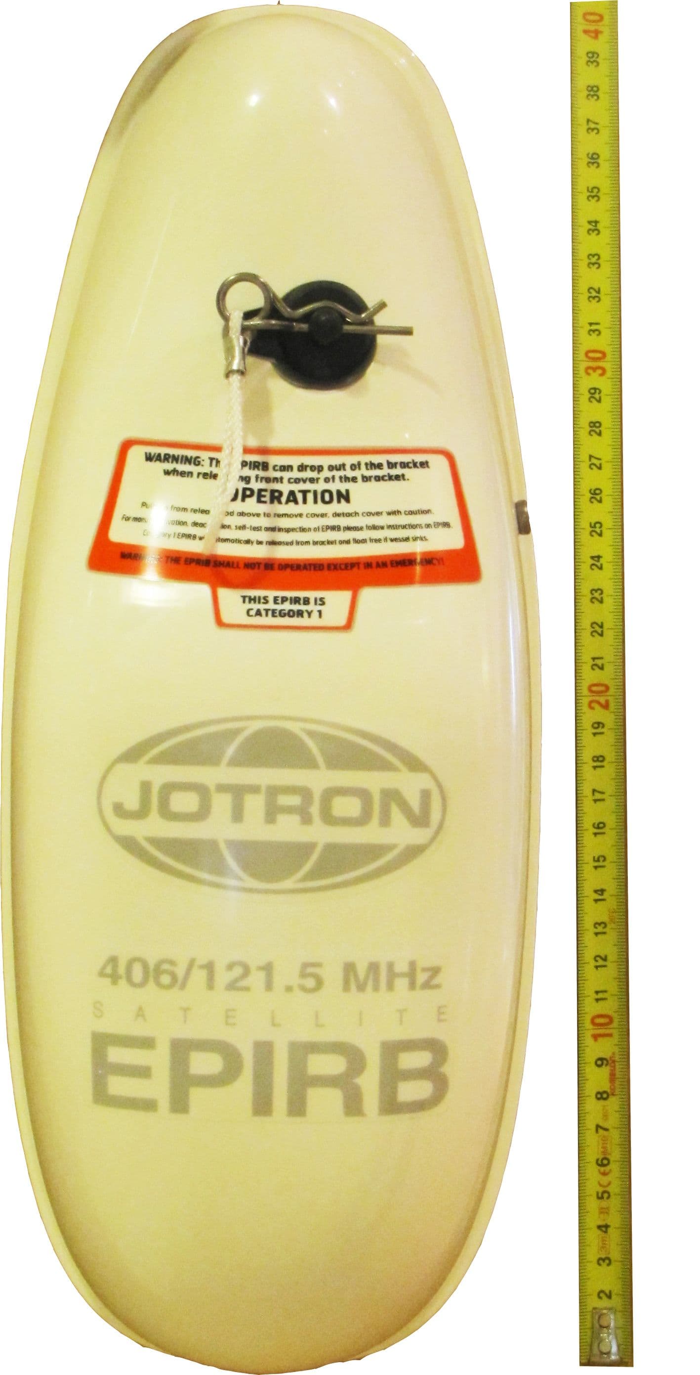
VRVTRON60GPS
Feb 12, 2013406 MHz EPIRB with GPS
Equipment Class
GEP - 406 MHz EPIRB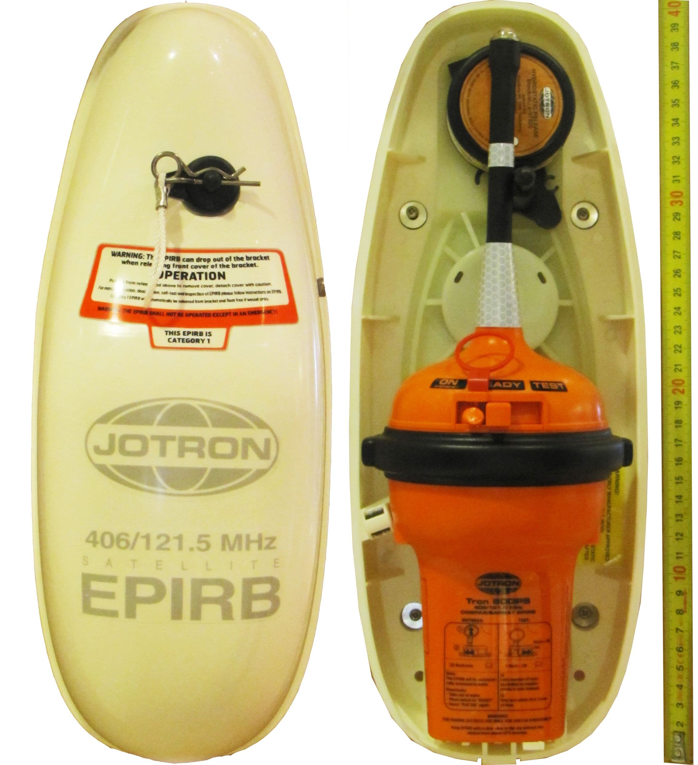
VRVTRON60S
Jan 01, 2013406 MHz EPIRB
Equipment Class
GEP - 406 MHz EPIRB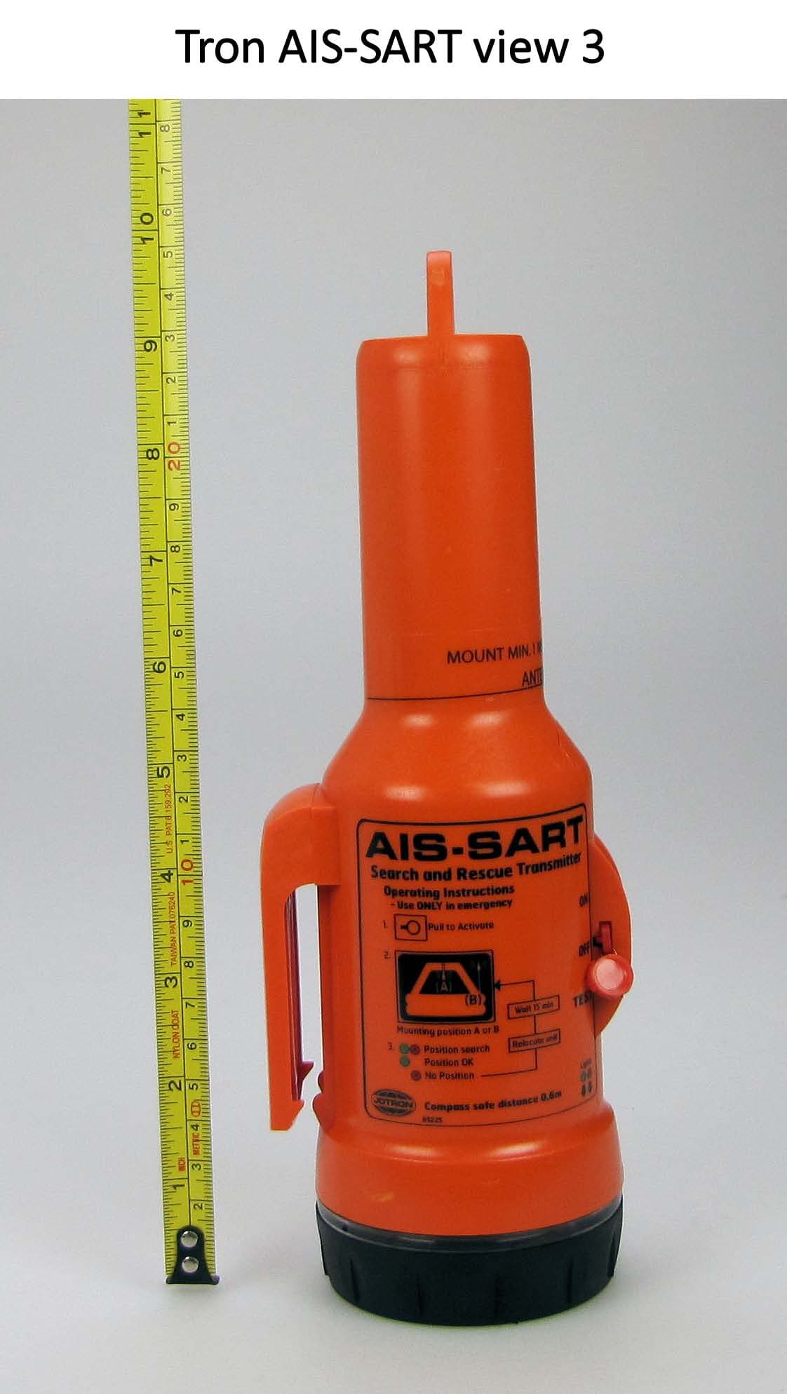
VRVTRONAISSART
Nov 17, 2010TRON AIS-SART
Equipment Class
AIS - Automatic Identification Systems
VRVTRONS-VDR
Mar 19, 2008Protective Capsule for S-VDR and EPIRB
Equipment Class
GEP - 406 MHz EPIRB