VRVTRONS-VDRProtective Capsule for S-VDR and EPIRB
Jotron AS
Click to zoom
Application Details
- Equipment Class
- GEP - 406 MHz EPIRB
- Date of Grant
- Mar 19, 2008
- Application Purpose
- Original Equipment
- Date of Application
- Oct 24, 2007
- Equipment Note
- Protective Capsule for S-VDR and EPIRB
- Frequency Range
- 121.50000000 - 121.50000000
- Company
- Jotron AS
- Country
- Norway
Documents & Files
Document Text
Text extracted from the exhibit documents filed with the FCC. Open a document above to read the original.
Users Manual
www.jotron.com Tron S-VDR CAPSULE USERS MANUAL 2 82310_UM_ SVDR_E EC Declaration of Conformity, available at www.jotron.com Abbreviations and definitions BAUD Transmission rate unit of measurement for binary coded data (bit per second). BIT Short form of Binary Digit. The smallest element of data in a binary-coded value. BITE Built in test equipment bps Bits Per Second. CHARACTER STRING Continuous characters (other than spaces) in a message. CHECKSUM The value sent with a binary-coded message to be checked at the receiving end to verify the integrity of the message. COSPAS COsmicheskaya Sistyema Poiska Avariynich Sudov (Space System for the Search of Vessels in Distress) CLOCK A precisely spaced, stable train of pulses generated within an electronic system to synchronize the timing of digital operations within the system. DEFAULT A condition that the navigator assumes automatically if no other condition is initiated by the operator. 82310_UM_ SVDR_E 3 EPIRB Emergency Position Indicating Radio Beacon FRM Final Recording Medium GLOBAL POSITIONING SYSTEM (GPS) The NAVSTAR Global Positioning System, which consists of or- biting satellites, a network of ground control stations, and user positioning and navigation equipment. The system has 24 satellites plus 3 active spare satellites in six orbital planes about 20,200 kilometers above the earth. GPS Global Position System GPS SYSTEM TIME Time corrected to Universal Time Coordinated (UTC) and used as the time standard by the user segment of the GPS system. IEC International Electro-technical Commission. IMO International Maritime Organization INTERFACE Electronic circuits that permit the passage of data between different types of devices; For example, the speed and heading interface circuit permits data from a speed log and compass to pass to the navigator processor. ITU International Telecommunication Union. LED Light Emitting Diode. 4 82310_UM_ SVDR_E LUT Local User Terminal (Ground Station) MCC Mission Control Center PROCESSOR The processor circuit card in the console that controls system operations and computes the positioning/navigation solutions. RCC Rescue Coordination Center SARSAT Search and Rescue Satellite-Aided Tracking System SOFTWARE Values programmed and preloaded into memory. The values represent a permanent set of instructions for running the automatic functions (computations) of the navigator. S-VDR Simplified Voyage Data Recorder VHF Very High Frequency -A set of frequencies in the MHz region. VSWR Voltage standing wave ratio 82310_UM_ SVDR_E 5 Amendment Record AMENDMENT NO. INCORP. BY DATE PAGE(S) VERSION REASON FOR CHANGE 1 ES 14.02.06 44 pages A Kontroll med dokumenter.doc 2 ES 21.03.06 37 B Chapter 6.1 Self-test 3 ES 13.11.06 28 C IP info 4 ES 18.04.07 Total: 44 D New company name 5 ES 01.10.07 28,29,33, 37,38 E Changed text Changed fuses 6 7 8 9 10 11 12 13 14 15 6 82310_UM_ SVDR_E The information in this book has been carefully checked and is believed to be accurate. However, no responsibility is assumed for inaccuracies. CAUTION! This equipment contains CMOS integrated circuits. Observe handling precautions to avoid static discharges which may damage these devices. Jotron AS reserves the right to make changes without further notice to any products or modules described herein to improve reliability, function or design. Jotron AS does not assume any liability arising out of the application or use of the described product. Jotron AS is a prime manufacturer of safety equipment designed for rescue of human lives and their property. For safety equipment to be effective in line with the design parameters it is important that they are handled, stowed and maintained in compliance with the manufacturers instructions. Jotron AS Cannot be held responsible for any damage caused due to incorrect use of the equipment or breach of laid down procedures or for failure of any specific component or other parts of the equipment. Jotron AS does not take any responsibility for improper disassembling/assembling of the equipment. We strongly recommend all service to be done by authorized Jotron agents. In addition to normal service, Jotron AS agents have the necessary equipment and education to test the operational functions of the beacon. 82310_UM_ SVDR_E 7 LIST OF CONTENTS 1 GENERAL DESCRIPTION 9 1.1 EPIRB MODULE 9 1.1.1 System description 10 1.1.2 Signal detection 10 1.1.3 Distress location determination 11 1.1.4 Added value in the EPIRB 13 1.1.5 EPIRB registration 14 1.2 S-VDR SERVER MODULE 15 2 TECHNICAL SPECIFICATION 16 3 FUNCTIONAL DESCRIPTION 18 3.1 GENERAL 18 3.1.1 Capsule housing 19 3.1.2 S-VDR Server module 19 3.1.3 EPIRB module 20 3.1.4 Battery module 21 3.1.5 Automatic release bracket, FBR-3 21 3.1.6 S-VDR Data and Power connections 22 3.1.6.1 S-VDR Data and Power connector, capsule 22 3.1.6.2 S-VDR Data and Power connector, bracket 23 3.1.7 Wiring table S-VDR Data and Power connection 24 4 INSTALLATION 25 4.1 MOUNTING BRACKET FBR-3 25 4.2 MOUNTING THE FBR-3 26 4.3 MOUNTING OF THE CAPSULE INTO THE FBR-3 26 4.4 REPLACEMENT AND MOUNTING OF THE HYDROSTATIC RELEASE MECHANISM 27 4.5 JUNCTION BOX 28 5 OPERATING INSTRUCTIONS 31 5.1 FBR-3 FLOAT FREE BRACKET 31 5.2 MANUAL OPERATION OF EPIRB MODULE 31 5.3 AUTOMATIC OPERATION OF EPIRB MODULE 32 8 82310_UM_ SVDR_E 5.4 TESTING THE EPIRB MODULE 32 5.5 OPERATION OF THE S-VDR MODULE 34 5.5.1 Operating software 34 5.6 CHANGE OF BATTERY 35 5.6.1 MSC Circ. 1039 35 5.6.2 Battery disposal 36 5.6.2.1 Incineration 36 5.6.2.2 Land filling 36 5.6.2.3 Recycling 36 6 MAINTENANCE AND TROUBLESHOOTING 37 6.1 EPIRB MODULE / BATTERY MODULE 37 6.2 TESTING EPIRB MODULE 37 6.2.1 Self-test with sea water contacts activated 37 6.2.2 Self-test with sea water contacts deactivated 37 6.3 MAINTENANCE OF EPIRB 38 6.3.1 EPIRB module error messages 40 6.4 TEST OF GPS RECEIVER WITHOUT TRANSMITTERS ACTIVATED 41 6.5 S-VDR MODULE 41 7 NOTES: 42 8 SERVICE AGENTS 43 82310_UM_ SVDR_E 9 1 GENERAL DESCRIPTION The Main parts of the C…
Text truncated - open the document above for the full version.
Attestation Statements
Tjodalyng: 29.10.2007 RE: CONFIDENTIALITY REQUEST FOR: FCC ID: VRVTRONS-VDR To whom it may concern: This letter serves as an official request for confidentiality under FCC rule section 0.459. We have requested that the following documents: Technical Manual, Users Manual, Schematic Description and Internal Photos required to be submitted with this application, to be withheld from public view. These documents are company property and must never get into the possession of Jotron AS competition. The sale and marketing of this equipment is limited to maritime projects and the equipment is sold directly to these customers. The equipment is not available for our competitors to study. Sincerely, Eirik Storjordet Certification Manager [email protected] Tel. +47 33139714 Fax. +47 33126780 Attn: Reviewing Engineer Federal Communications Commission 7435 Oakland Mills Road Columbia, MD 21046 USA
Attestation Statements
Arkivsystem for etiketter i pdf-format Dato:10.03.2006 Etikettens x-nummer: x-81960 Etikettens navn: OPERATION INSTRUCTIONS TRON S-VDR Etikettens format:Bredde: 248 mm - høyde 78 mm Folietype:Fascal 805 orange Folie Trykkfarge:Sort Ferdiggjøring:Stanses
Attestation Statements
18.04.2005
Attestation Statements
251194_x-81958 21-09-05 10:53 Side 1
Attestation Statements
: m e t s y s R D V - S : o n l a i r e S : N I U , e d o c x e H : l e s s e v f o e m a N : . n g i s l l a c / I S M M : D I C C F V R V T R O N S - V D R D I S T A N C E C O M P A S S S A F E T Y 1,25 m 0470/08 3280 TJODALYNG NORW AY www.jotron.com C o s p a s - S a r s a t A p p r o v e d n o . 1 5 5 M i n i m u m o p e r a t i n g t i m e 1 6 8 h o u r s . V O Y A G E D A T A R E C O R D E R R E P O R T T O A U T H O R I T I E S D O N O T O P E N T r o n S - V D R C A P S U L E 4 0 6 . 0 2 8 M H z C o s p a s - S a r s a t E P I R B w / G P S . H o m i n g : 1 2 1 . 5 M H z S - V D R F i n a l R e c o r d i n g M e d i u m This device complies with GMDSS provision of part 80 of the FCC rules Dato: Etikettens x-nummer: Etikettens navn: Etikettens format: Folietype:Try kkfarge: 18.06.05 81959 Rev.D, 29.10.2007 SERIAL NUMBER TRON S-VDR CAPSULE Bredde: 328mm Høyde: 52 mm. FAS CAL 805 ORANGE SORT A r k i vsys t e m f o r e t i ke tt e r i pd f - f o r m a t .
Attestation Statements
TAC Number: 155 Beacon Model Name: Tron S-VDR CAPSULE Type: FF=Float Free FF EPIRB In Production: Yes Manufacturer: Jotron AS TAC Date: 06-Feb-06 TAC Rev Date: 11-Jul-07 TAC Rev History: (1) 28- Aug-06: approved with alternative GPS receiver module 'Jupiter 21'; (2) 11-Jul-07: L3- FFSVDR added to TAC-155 (3)11-Jul-07: manufacturer's name change from 'Jotron Electronics A.S.' to 'Jotron AS' Battery: Manufacturer (Model, No of Cells) SAFT LSH20, 8xD-size cells Class 2 Tx Frequencies: 406.028 MHz Tested Life: (24 / 48 hrs) 48 Self Test: Yes Self Test RF: Yes Self Test RF (Short/Long): Long Self Test Format Flag: Long Self Test Consistent with 15 Hex ID: Yes Homer Freq: 121.5 MHz Homer Duty Cycle: Continuous Homer Power: 100mW Strobe Light: Yes Strobe Brightness: 1.0 cd Strobe Duty Cycle: 21 flashes/minute Nav Device: Int Nav Device Model: Connexant (type:Jupiter LP), Navman (model: Jupiter 21) Separable Antenna: No Antenna Model: Additional Functions: Comments General: Beacon has demonstrated compliance with C/S requirements during an extended 168 hours lifetime at minimum temperature test; model 'L-3 FFSVDR' (PN-82707) is a variant of 'Tron S-VDR Capsule'(PN- 83700), equipped with a final recording media module 'L3-FRM' Protocols Tested: UL, SL Database ID: 155 Database ID: 155 Protocol Notes: U=User; UL=User Location; SL=Standard Location; NL=National Location Additional Names: L-3 FFSVDR
Attestation Statements
TAC Number: 155 Beacon Model Name: Tron S-VDR CAPSULE Type: FF=Float Free FF EPIRB In Production: Yes Manufacturer: Jotron AS TAC Date: 06-Feb-06 TAC Rev Date: 11-Jul-07 TAC Rev History: (1) 28- Aug-06: approved with alternative GPS receiver module 'Jupiter 21'; (2) 11-Jul-07: L3- FFSVDR added to TAC-155 (3)11-Jul-07: manufacturer's name change from 'Jotron Electronics A.S.' to 'Jotron AS' Battery: Manufacturer (Model, No of Cells) SAFT LSH20, 8xD-size cells Class 2 Tx Frequencies: 406.028 MHz Tested Life: (24 / 48 hrs) 48 Self Test: Yes Self Test RF: Yes Self Test RF (Short/Long): Long Self Test Format Flag: Long Self Test Consistent with 15 Hex ID: Yes Homer Freq: 121.5 MHz Homer Duty Cycle: Continuous Homer Power: 100mW Strobe Light: Yes Strobe Brightness: 1.0 cd Strobe Duty Cycle: 21 flashes/minute Nav Device: Int Nav Device Model: Connexant (type:Jupiter LP), Navman (model: Jupiter 21) Separable Antenna: No Antenna Model: Additional Functions: Comments General: Beacon has demonstrated compliance with C/S requirements during an extended 168 hours lifetime at minimum temperature test; model 'L-3 FFSVDR' (PN-82707) is a variant of 'Tron S-VDR Capsule'(PN- 83700), equipped with a final recording media module 'L3-FRM' Protocols Tested: UL, SL Database ID: 155 Database ID: 155 Protocol Notes: U=User; UL=User Location; SL=Standard Location; NL=National Location Additional Names: L-3 FFSVDR
Block Diagram
Tron S-VDR CAPSULE FLOAT DIAGRAM FD-83700 Page 1(1) CHANGE STATUS:MADE BY:ACCEPT: NO.DATE:SIGN.:CH.NO.: 01.02.06 Bente Jensen X-82376 SW MODULE X-82217 EPIRB Module X-99750 Tron 40S GPS IF Board X-81846 Upper Capsule Assembly X-82392 Lower Housing Module X-81847 Lower Capsule Assembly X-83700 Complete Tron S-VDR Capsule X-82389 Upper Housing Module X-81848 S-VDR Servver Module X-99631 Server Board X-82193 Flashdisk Board X-81904 Compl.Con. Module X-82206 Battery Module X-81856/X-82310 MANUAL MODULE X-81853 RF-Board UHF/VHF X-82390 Antenna Module
Cover Letter(s)
Tjodalyng: 14.03.2008 RE: CONFIDENTIALITY REQUEST FOR: FCC ID: VRVTRONS-VDR To whom it may concern: This letter serves as an official request for confidentiality under FCC rule section 0.459. We have requested that the following documents: Technical Manual, Schematic Description and Internal Photos required to be submitted with this application, to be withheld from public view. These documents are company property and must never get into the possession of Jotron AS competition. The sale and marketing of this equipment is limited to maritime projects and the equipment is sold directly to these customers. The equipment is not available for our competitors to study. Sincerely, Eirik Storjordet Certification Manager [email protected] Tel. +47 33139714 Fax. +47 33126780 Attn: Reviewing Engineer Federal Communications Commission 7435 Oakland Mills Road Columbia, MD 21046 USA
ID Label/Location Info
FCC ID label and label placement The color shown at this label is not correct. The real color is FASCAL 805 ORANGE.
Operational Description
www.jotron.com Tron S-VDR CAPSULE USERS MANUAL 2 82310_UM_ SVDR_E EC Declaration of Conformity, available at www.jotron.com Abbreviations and definitions BAUD Transmission rate unit of measurement for binary coded data (bit per second). BIT Short form of Binary Digit. The smallest element of data in a binary-coded value. BITE Built in test equipment bps Bits Per Second. CHARACTER STRING Continuous characters (other than spaces) in a message. CHECKSUM The value sent with a binary-coded message to be checked at the receiving end to verify the integrity of the message. COSPAS COsmicheskaya Sistyema Poiska Avariynich Sudov (Space System for the Search of Vessels in Distress) CLOCK A precisely spaced, stable train of pulses generated within an electronic system to synchronize the timing of digital operations within the system. DEFAULT A condition that the navigator assumes automatically if no other condition is initiated by the operator. 82310_UM_ SVDR_E 3 EPIRB Emergency Position Indicating Radio Beacon FRM Final Recording Medium GLOBAL POSITIONING SYSTEM (GPS) The NAVSTAR Global Positioning System, which consists of or- biting satellites, a network of ground control stations, and user positioning and navigation equipment. The system has 24 satellites plus 3 active spare satellites in six orbital planes about 20,200 kilometers above the earth. GPS Global Position System GPS SYSTEM TIME Time corrected to Universal Time Coordinated (UTC) and used as the time standard by the user segment of the GPS system. IEC International Electro-technical Commission. IMO International Maritime Organization INTERFACE Electronic circuits that permit the passage of data between different types of devices; For example, the speed and heading interface circuit permits data from a speed log and compass to pass to the navigator processor. ITU International Telecommunication Union. LED Light Emitting Diode. 4 82310_UM_ SVDR_E LUT Local User Terminal (Ground Station) MCC Mission Control Center PROCESSOR The processor circuit card in the console that controls system operations and computes the positioning/navigation solutions. RCC Rescue Coordination Center SARSAT Search and Rescue Satellite-Aided Tracking System SOFTWARE Values programmed and preloaded into memory. The values represent a permanent set of instructions for running the automatic functions (computations) of the navigator. S-VDR Simplified Voyage Data Recorder VHF Very High Frequency -A set of frequencies in the MHz region. VSWR Voltage standing wave ratio 82310_UM_ SVDR_E 5 Amendment Record AMENDMENT NO. INCORP. BY DATE PAGE(S) VERSION REASON FOR CHANGE 1 ES 14.02.06 44 pages A Kontroll med dokumenter.doc 2 ES 21.03.06 37 B Chapter 6.1 Self-test 3 ES 13.11.06 28 C IP info 4 ES 18.04.07 Total: 44 D New company name 5 ES 01.10.07 28,29,33, 37,38 E Changed text Changed fuses 6 7 8 9 10 11 12 13 14 15 6 82310_UM_ SVDR_E The information in this book has been carefully checked and is believed to be accurate. However, no responsibility is assumed for inaccuracies. CAUTION! This equipment contains CMOS integrated circuits. Observe handling precautions to avoid static discharges which may damage these devices. Jotron AS reserves the right to make changes without further notice to any products or modules described herein to improve reliability, function or design. Jotron AS does not assume any liability arising out of the application or use of the described product. Jotron AS is a prime manufacturer of safety equipment designed for rescue of human lives and their property. For safety equipment to be effective in line with the design parameters it is important that they are handled, stowed and maintained in compliance with the manufacturers instructions. Jotron AS Cannot be held responsible for any damage caused due to incorrect use of the equipment or breach of laid down procedures or for failure of any specific component or other parts of the equipment. Jotron AS does not take any responsibility for improper disassembling/assembling of the equipment. We strongly recommend all service to be done by authorized Jotron agents. In addition to normal service, Jotron AS agents have the necessary equipment and education to test the operational functions of the beacon. 82310_UM_ SVDR_E 7 LIST OF CONTENTS 1 GENERAL DESCRIPTION 9 1.1 EPIRB MODULE 9 1.1.1 System description 10 1.1.2 Signal detection 10 1.1.3 Distress location determination 11 1.1.4 Added value in the EPIRB 13 1.1.5 EPIRB registration 14 1.2 S-VDR SERVER MODULE 15 2 TECHNICAL SPECIFICATION 16 3 FUNCTIONAL DESCRIPTION 18 3.1 GENERAL 18 3.1.1 Capsule housing 19 3.1.2 S-VDR Server module 19 3.1.3 EPIRB module 20 3.1.4 Battery module 21 3.1.5 Automatic release bracket, FBR-3 21 3.1.6 S-VDR Data and Power connections 22 3.1.6.1 S-VDR Data and Power connector, capsule 22 3.1.6.2 S-VDR Data and Power connector, bracket 23 3.1.7 Wiring table S-VDR Data and Power connection 24 4 INSTALLATION 25 4.1 MOUNTING BRACKET FBR-3 25 4.2 MOUNTING THE FBR-3 26 4.3 MOUNTING OF THE CAPSULE INTO THE FBR-3 26 4.4 REPLACEMENT AND MOUNTING OF THE HYDROSTATIC RELEASE MECHANISM 27 4.5 JUNCTION BOX 28 5 OPERATING INSTRUCTIONS 31 5.1 FBR-3 FLOAT FREE BRACKET 31 5.2 MANUAL OPERATION OF EPIRB MODULE 31 5.3 AUTOMATIC OPERATION OF EPIRB MODULE 32 8 82310_UM_ SVDR_E 5.4 TESTING THE EPIRB MODULE 32 5.5 OPERATION OF THE S-VDR MODULE 34 5.5.1 Operating software 34 5.6 CHANGE OF BATTERY 35 5.6.1 MSC Circ. 1039 35 5.6.2 Battery disposal 36 5.6.2.1 Incineration 36 5.6.2.2 Land filling 36 5.6.2.3 Recycling 36 6 MAINTENANCE AND TROUBLESHOOTING 37 6.1 EPIRB MODULE / BATTERY MODULE 37 6.2 TESTING EPIRB MODULE 37 6.2.1 Self-test with sea water contacts activated 37 6.2.2 Self-test with sea water contacts deactivated 37 6.3 MAINTENANCE OF EPIRB 38 6.3.1 EPIRB module error messages 40 6.4 TEST OF GPS RECEIVER WITHOUT TRANSMITTERS ACTIVATED 41 6.5 S-VDR MODULE 41 7 NOTES: 42 8 SERVICE AGENTS 43 82310_UM_ SVDR_E 9 1 GENERAL DESCRIPTION The Main parts of the C…
Text truncated - open the document above for the full version.
Test Report
Document 75900372 Report 03 Issue 1 November 2007 Report On Emergency Beacons Testing of the Jotron AS Tron S-VDR Capsule and L3-FFSVR COMMERCIAL-IN-CONFIDENCE TUV Product Service Ltd, Octagon House, Concorde Way, Segensworth North, Fareham, Hampshire, United Kingdom, PO15 5RL Tel: +44 (0) 1489 558100. Website: www.tuvps.co.uk COMMERCIAL-IN-CONFIDENCE Document 75900372 Report 03 Issue 1 Page 1 of 160 COMMERCIAL-IN-CONFIDENCE Emergency Beacons Testing of the Jotron AS Tron S-VDR Capsule and L3-FFSVR Document 75900372 Report 03 Issue 1 November 2007 REPORT ON PREPARED FOR Jotron AS Østbyveien 1 PO. BOX 54 3280 Tjodalyng Norway PREPARED BY R Hampton Test Engineer APPROVED BY N Forsyth Authorised Signatory DATED 2 nd November 2007 COMMERCIAL-IN-CONFIDENCE Document 75900372 Report 03 Issue 1 Page 2 of 160 COMMERCIAL-IN-CONFIDENCE CONTENTS Section Page No 1 REPORT SUMMARY ................................................................................................................... 3 1.1 Introduction ................................................................................................................................... 4 1.2 Application Form........................................................................................................................... 6 1.3 Product Information .................................................................................................................... 11 1.4 Deviations from the Standard ..................................................................................................... 13 1.5 Modification Record .................................................................................................................... 13 1.6 Alternative Test Site.................................................................................................................... 13 2 TEST DETAILS .......................................................................................................................... 14 2.1 Initial Aliveness Test ................................................................................................................... 22 2.2 Dry Heat Cycle............................................................................................................................ 25 2.3 Damp Heat Cycle........................................................................................................................ 31 2.4 Vibration Test.............................................................................................................................. 35 2.5 Bump Test .................................................................................................................................. 42 2.6 Salt Fog Test .............................................................................................................................. 45 2.7 Drop Test (On Hard Surface) .....................................................................................................49 2.8 Drop Test (In Water) ................................................................................................................... 53 2.9 Leakage And Immersion Test.....................................................................................................60 2.10 Spurious Emissions Test ............................................................................................................ 63 2.11 Low-Temperature Thermal Shock Test...................................................................................... 70 2.12 High-Temperature Thermal Shock Test ..................................................................................... 75 2.13 Operational Life Test .................................................................................................................. 80 2.14 Strobe Light Test ...................................................................................................................... 104 2.15 Self-test..................................................................................................................................... 107 2.16 Automatic Release Mechanism And Automatic Activation Tests............................................. 115 2.17 Stability And Buoyancy Test ..................................................................................................... 116 2.18 Inadvertent Activation Test ....................................................................................................... 119 2.19 Carrier Frequency Test............................................................................................................. 120 2.20 Modulation Characteristics (Transmitter Duty cycle)................................................................ 121 2.21 Modulation Characteristics (Modulation Frequency And Sweep Repetition Rate, Modulation Duty Cycle) ................................................................................................................................ 125 2.22 Modulation Characteristics (Modulation Factor)....................................................................... 127 2.23 Modulation Characteristics (Frequency Coherence)................................................................ 131 2.24 Peak Effective Radiated Power ................................................................................................ 138 2.25 VSWR Measurement ................................................................................................................ 139 2.26 Humidity Test............................................................................................................................ 140 2.27 Orientation Test ........................................................................................................................ 144 3 TEST EQUIPMENT USED ....................................................................................................... 149 3.1 Test Equip…
Text truncated - open the document above for the full version.
Test Report
COMMERCIAL-IN-CONFIDENCE Document 75900372 Report 03 Issue 1 Page 101 of 160 COMMERCIAL-IN-CONFIDENCE 96979899100101102103104105106107108 10 12 14 16 18 20 22 24 26 Hours dBm Power Output (121.5 MHz) Project Number - 75900372 Product - Tron S-VDR Capsule Seral Number - 00169 Power Graph 11 108109110111112113114115116117118118120 10 12 14 16 18 20 22 24 26 Hours dBm Power Output (121.5 MHz) Project Number - 75900372 Product - Tron S-VDR Capsule Seral Number - 00169 Power Graph 12 COMMERCIAL-IN-CONFIDENCE Document 75900372 Report 03 Issue 1 Page 102 of 160 COMMERCIAL-IN-CONFIDENCE 120121122123124125126127128129130131132 10 12 14 16 18 20 22 24 26 Hours dBm Power Output (121.5 MHz) Project Number - 75900372 Product - Tron S-VDR Capsule Seral Number - 00169 Power Graph 13 132133134135136137138139140141142143144 10 12 14 16 18 20 22 24 26 Hours dBm Power Output (121.5 MHz) Project Number - 75900372 Product - Tron S-VDR Capsule Seral Number - 00169 Power Graph 14 COMMERCIAL-IN-CONFIDENCE Document 75900372 Report 03 Issue 1 Page 103 of 160 COMMERCIAL-IN-CONFIDENCE 144145146147148149150151152153154155156 10 12 14 16 18 20 22 24 26 Hours dBm Power Output (121.5 MHz) Project Number - 75900372 Product - Tron S-VDR Capsule Seral Number - 00169 Power Graph 15 156157158159160161162163164165166167168 10 12 14 16 18 20 22 24 26 Hours dBm Power Output (121.5 MHz) Project Number - 75900372 Product - Tron S-VDR Capsule Seral Number - 00169 Power Graph 16 COMMERCIAL-IN-CONFIDENCE Document 75900372 Report 03 Issue 1 Page 104 of 160 COMMERCIAL-IN-CONFIDENCE 2.14 STROBE LIGHT TEST 2.14.1 Specification Reference RTCM Paper 77-2002/SC110-STD, Clause A13.2 2.14.2 Equipment Under Test TÜV testing only: Tron S-VDR Capsule, Serial Number 00169; and Tron S-VDR Capsule with bracket, Serial Number: 100AA102. Note: this sample not TÜV controlled, see Test Results, below. 2.14.3 Date of Test and Modification State TÜV testing only: 4 th October 2007 - Modification State 1 2.14.4 Test Equipment Used TÜV testing only: The major items of test equipment used for the above tests are identified in Section 3.1. 2.14.5 Test Set-up and Operating Modes TÜV testing only: The test was performed with the EUT in the following mode(s): Operating 2.14.6 Environmental Conditions Ambient Temperature 21.6°C Relative Humidity 55% Atmospheric Pressure 1018mbar 2.14.7 Test Results Tests (see note, below) completed as per customer supplied information, see Annex A. Note: All tests completed as per customer supplied information under Clause A13.2 except strobe light duration; this was not completed at extreme operating temperatures. Test was conducted under the scope of this report at all three temperatures – extreme operating high, low and ambient for comparison (customer supplied information indicated a pulse duration of approximately 40us). Strobe Light Duration Summary Test Results Parameter Units T min (-20°C) T amb (21.6°C) T max (+55°C) Pulse duration, 10% Points Us 39.4 39.9 38.9 COMMERCIAL-IN-CONFIDENCE Document 75900372 Report 03 Issue 1 Page 105 of 160 COMMERCIAL-IN-CONFIDENCE Pulse Duration – Ambient Pulse Duration – High Temperature (+55°C) 4-Oct-07 13 39 08 10 s 2.00 V 12.38 V DC 12.04 V 10 s 2 V 1 V DC 10 MS/s STOPPED 4-Oct-07 11 14 37 10 s 2.00 V -0.06 V DC 12.04 V t 39.90s 25.062 kHz 10 s 2 V 1 V DC 10 MS/s STOPPED COMMERCIAL-IN-CONFIDENCE Document 75900372 Report 03 Issue 1 Page 106 of 160 COMMERCIAL-IN-CONFIDENCE Pulse Duration – Low Temperature (-20°C) 4-Oct-07 18 21 33 10 s 2.00 V 0.01 V MEASURE Off Cursors Parameters mode Time Amplitude type Relative Absolute show Diff - Ref Diff & Ref Reference cursor Track Off On Difference cursor DC 12.04 V t 38.90s 25.706 kHz 10 s 2 V 1 V DC 10 MS/s STOPPED COMMERCIAL-IN-CONFIDENCE Document 75900372 Report 03 Issue 1 Page 107 of 160 COMMERCIAL-IN-CONFIDENCE 2.15 SELF-TEST 2.15.1 Specification Reference RTCM Paper 77-2002/SC110-STD, Clause A13.2 2.15.2 Equipment Under Test Tron S-VDR Capsule, Serial Number 00169 2.15.3 Date of Test and Modification State Test at Ambient: 30 th August 2007 - Modification State 1 Test at +55°C: 22 nd June 2007 - Modification State 0 Test at -20°C: 11 th July 2007 - Modification State 0 2.15.4 Test Equipment Used The major items of test equipment used for the above tests are identified in Section 3.1. 2.15.5 Test Set-up and Operating Modes The test was performed with the EUT in the following mode(s): Operating and Self-test 2.15.6 Environmental Conditions 20 th June 2007 11 th July 2007 30 th August 2007 Ambient Temperature 23.5°C 24.2°C 22.0°C Atmospheric Pressure 1004mbar 1008mbar 1017mbar 2.15.7 Test Results Summary of Aliveness test results Stage Pass / Fail Ambient Aliveness Test Pass Ambient Self-test Pass High Temperature (+55°C) Aliveness Test Pass High Temperature (+55°C) Self-test Pass Low Temperature (-20°C) Aliveness Test Pass Low Temperature (-20°C) Self-test Pass COMMERCIAL-IN-CONFIDENCE Document 75900372 Report 03 Issue 1 Page 108 of 160 COMMERCIAL-IN-CONFIDENCE Beacon Test Report (Aliveness Test, Ambient Temperature) COMMERCIAL-IN-CONFIDENCE Document 75900372 Report 03 Issue 1 Page 109 of 160 COMMERCIAL-IN-CONFIDENCE Beacon Test Report (Self-test, Ambient Temperature) COMMERCIAL-IN-CONFIDENCE Document 75900372 Report 03 Issue 1 Page 110 of 160 COMMERCIAL-IN-CONFIDENCE Beacon Test Report (Aliveness Test, High Temperature, +55°C) COMMERCIAL-IN-CONFIDENCE Document 75900372 Report 03 Issue 1 Page 111…
Text truncated - open the document above for the full version.
Contact Information
Applicant
Frank Loke(Certification Manager)
Technical Contact
Non-Technical Contact
EirikStorjordet
[email protected]+4733139714
Test Firm
TUV SUD Product ServiceMark Jenkins
Technical Specifications
| # | Rule Parts | Frequency Range | Power Output | Emission | Tolerance |
|---|---|---|---|---|---|
| 2 | 80.1101(c)(5) | 121.5 MHz - 121.5 MHz | 75.00 mW | 3K20A3X | 10 ppm |
Other Applications from Jotron AS
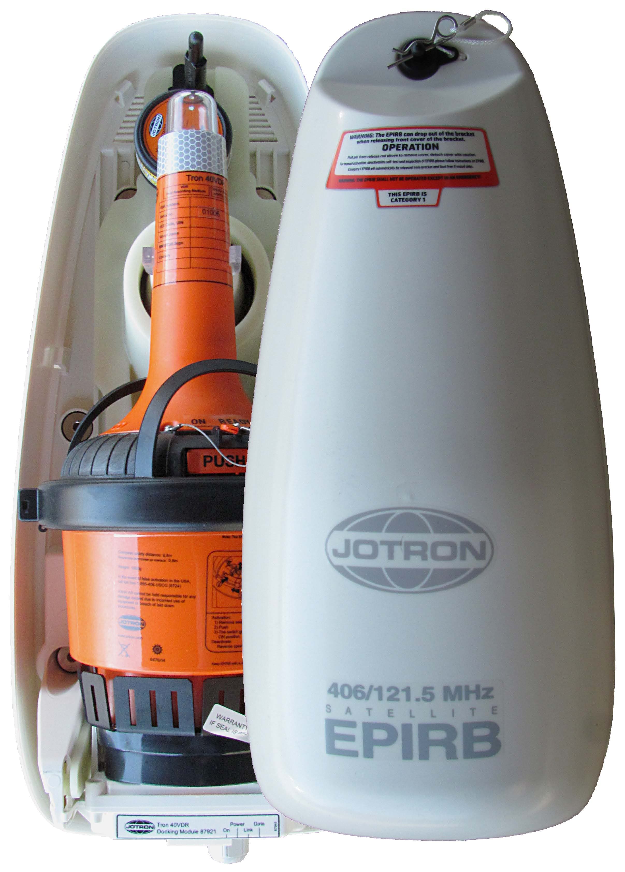
VRVTRON40VDR
Aug 30, 2015Float Free EPIRB with VDR
Equipment Class
GEP - 406 MHz EPIRB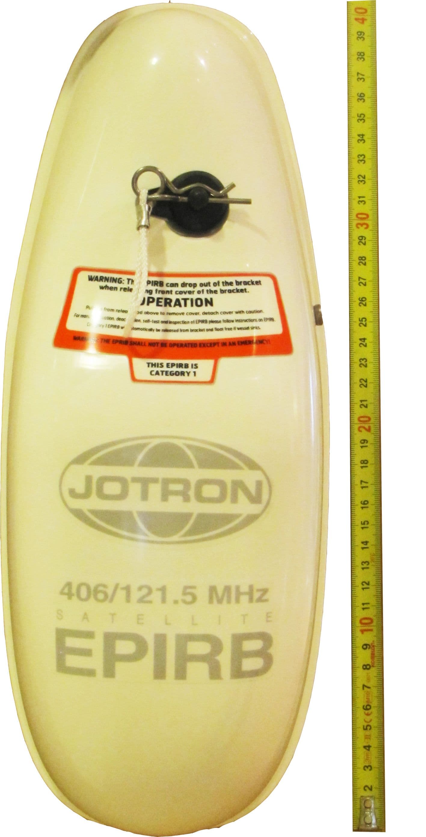
VRVTRON60GPS
Feb 12, 2013406 MHz EPIRB with GPS
Equipment Class
GEP - 406 MHz EPIRB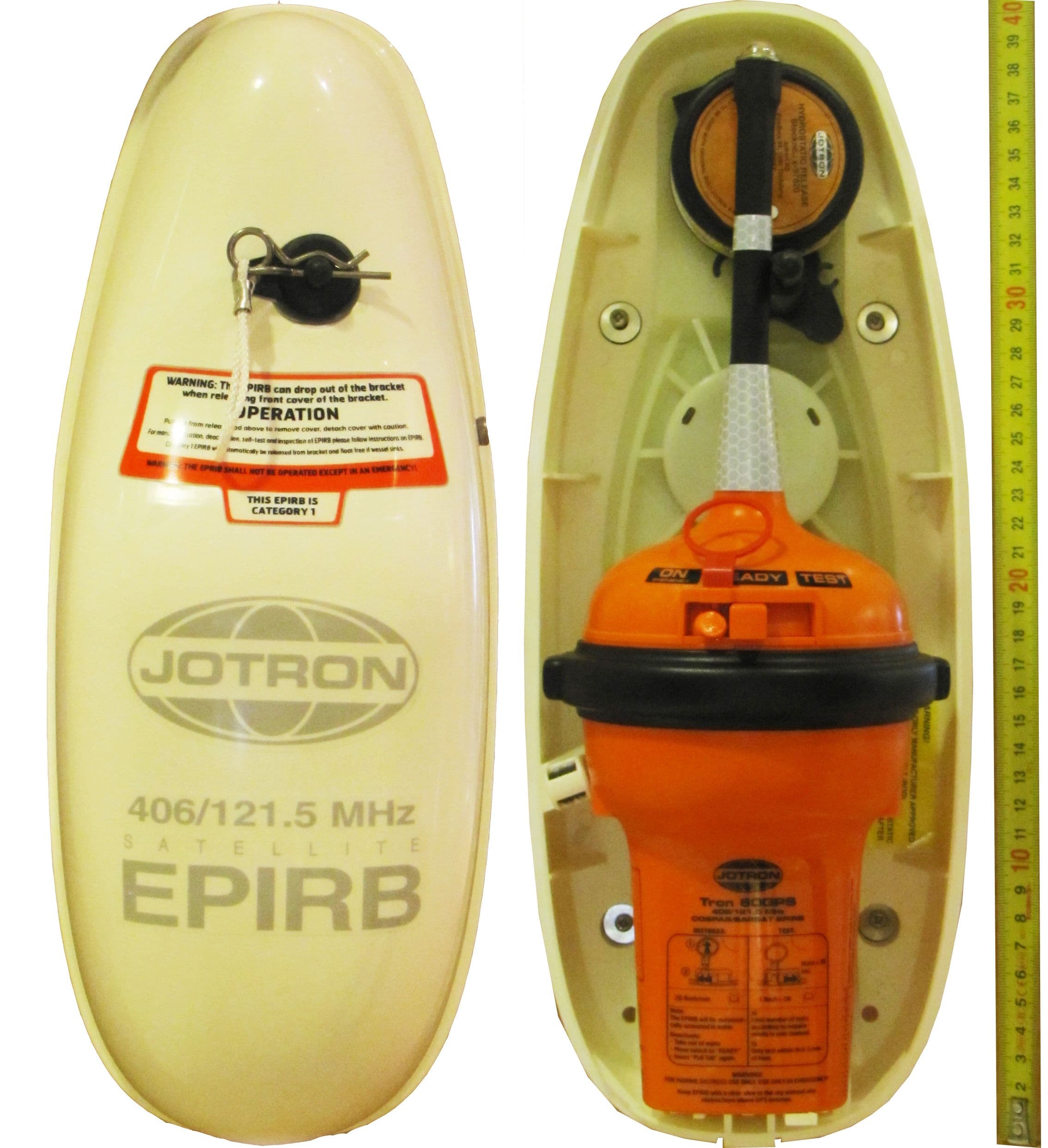
VRVTRON60S
Jan 01, 2013406 MHz EPIRB
Equipment Class
GEP - 406 MHz EPIRB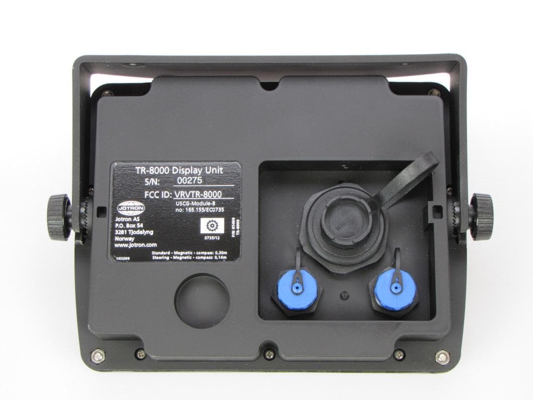
VRVTR8000
Oct 25, 2012Tron AIS TR-8000
Equipment Class
AIS - Automatic Identification Systems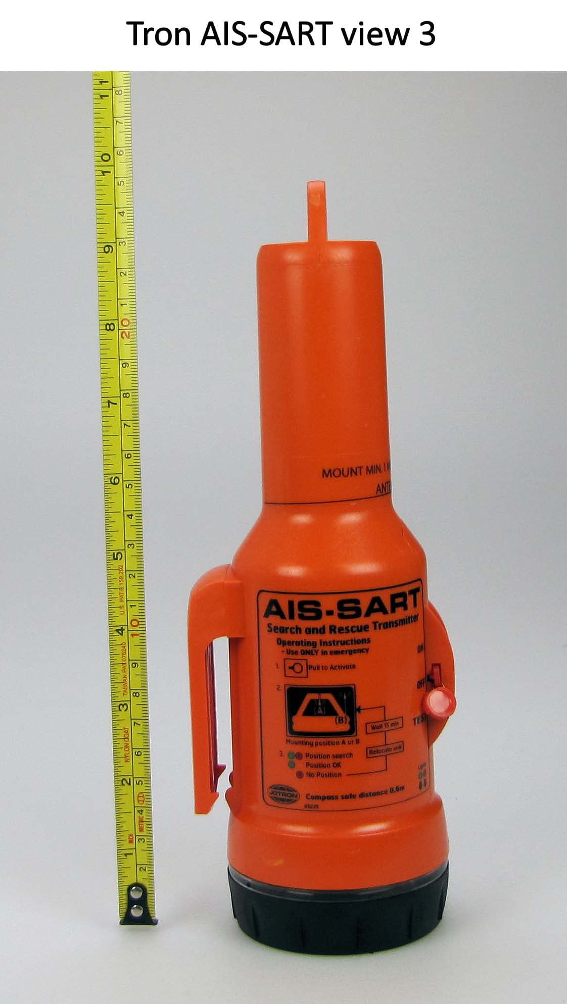
VRVTRONAISSART
Nov 17, 2010TRON AIS-SART
Equipment Class
AIS - Automatic Identification Systems