VRVTRONAISSARTTRON AIS-SART
Jotron AS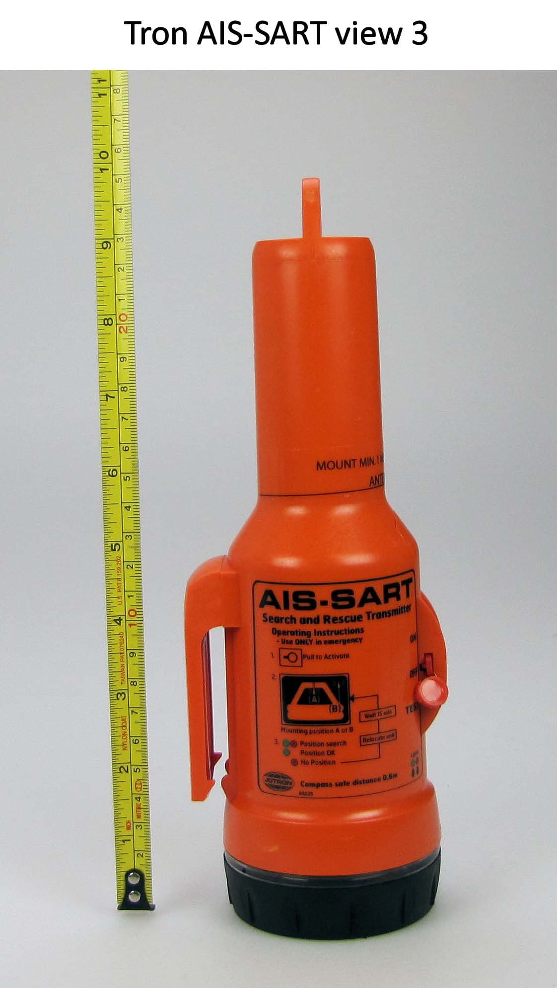
Click to zoom
Application Details
- Equipment Class
- AIS - Automatic Identification Systems
- Date of Grant
- Nov 17, 2010
- Application Purpose
- Original Equipment
- Date of Application
- Oct 07, 2010
- Equipment Note
- TRON AIS-SART
- Frequency Range
- 161.97500000 - 162.02500000
- Company
- Jotron AS
- Country
- Norway
Documents & Files
Document Text
Text extracted from the exhibit documents filed with the FCC. Open a document above to read the original.
Users Manual
USERS MANUAL www.jotron.com Tron AIS-SART 85355_UM_AIS-SART_F www.jotron.com www.jotron.com EC Declaration of Conformity, available at www.jotron.com The serial number is identical to the user ID of the unit. 2 Abbreviations and definitions EMC Electromagnetic Compatibility LED Light Emitting Diode PWB Printed Wire Board RF Radio Frequency AIS-SART Search and Rescue Unit based on the AIS system VHF Very High Frequency www.jotron.com 85355_UM_AIS-SART_F www.jotron.com 3 AMEND- INCORP. DATE PAGE(S) VERSION REASON MENT NO. BY FOR CHANGE 1 ES 16.06.09 Total: 28 A New product 2 ES 22.11.09 Page 2 B New information 3 FIT 08.12.09 Page 22-27 C Updated information 4 FIT 22.03.10 Total: 30 D Updated information 5 FIT 20.04.10 Total: 34 E Updated information 6 FIT 10.06.10 Page 28 F Updated information 7 8 Amendment Records The information in this book has been carefully checked and is believed to be accurate. However, no responsibility is assumed for inaccuracies. Jotron AS reserves the right to make changes without further notice to any pro- ducts or modules described herein to improve reliability, function or design. Jo- tron AS does not assume any liability arising out of the application or use of the described product. This equipment contains CMOS integrated circuits. Observe handling precautions to avoid static discharges which may damage these devices. 85355_UM_AIS-SART_F www.jotron.com www.jotron.com Jotron AS is a prime manufacturer of safety equipment designed for rescue of human lives and their property. For safety equipment to be effective in line with the design parameters it is important that they are handled, stowed and maintained in compli- ance with the manufacturers instructions. Jotron AS cannot be held responsible for any damage caused due to incorrect use of the equipment or breach of laid down procedures or for failure of any specific component or other parts of the equipment. The chapter covering battery replacement (6.2.1) is added for information only. Jo- tron AS does not take any responsibility for improper disassembling/assembling of the beacon. We strongly recommend all service to be done by authorized Jotron agents. In addition to normal service, Jotron agents have the necessary equipment and knowledge to test the operational functions of the beacon. Non-original mainte- nance and/or service parts may destroy the equipment function and performance. WARNING / IMPORTANT 4 Battery safety data sheet (Form: EEC directive 91/155) (2) SAFETY ADVICE S2 Keep out of reach of children. S8 Keep container dry. S26 In case of contact with eyes, rinse immediately with plenty of water and seek medical advice. S43 In case of fire, use D type extinguishers. Never use water. S45 In case of accident or if you feel unwell, seek medical advice immediately (show the label where possible). (3) FIRST AID MEASURES In case of contact of cell contents with eyes, flush immediately with water for 15 min. With skin, wash with plenty of water and take off contaminated clothes. If inhaled, remove from exposure, give oxygen, and seek medical advice. (4) FIRE-FIGHTING MEASURES Extinguishing media Suitable: Type D fire extinguishers Not to be used: Water - CO2 - Halon, dry chemical or foam extinguishers Special exposure hazards Generation of chlorine, sulphur dioxide, disulphur dichloride during thermal decomposition. Special protective equipment Use protective working boots, rubber apron and safety glasses with side shields. www.jotron.com 85355_UM_AIS-SART_F www.jotron.com 5 85355_UM_AIS-SART_F www.jotron.com www.jotron.com Table of contents 1 General description 8 1.1 Tron AIS-SART features 9 1.2 Battery module 10 2 Technical specifications 11 2.1 Electrical specifications 11 2.2 Mechanical specification 11 3 Functional description 12 3.1 General 12 3.1.1 Tron AIS-SART electronic assembly 12 3.1.2 Battery module 13 3.1.3 Bottom lid 13 4 Installation 14 4.1 Brackets 14 4.1.1 Wall bracket 14 4.1.2 Lifeboat bracket 15 4.2 Installation tips 17 4.2.1 How to use the brackets in life rafts 17 4.2.2 Installation diagram 18 4.2.3 Mounting a pipe 18 4.3 Using the telescopic pole 20 4.4 Using the 10m rope 21 5 Operating instructions 22 5.1 Activation 22 5.2 Reception on nearby vessels AIS transponders and ECS/ECDIS or chart plotters 23 5.2.1 Reception on a non AIS-SART compliant AIS transponder 23 5.2.2 Reception on a non AIS-SART compliant electronic chart (ECS/ECDIS) 23 5.2.3 Reception on an AIS-SART compliant AIS transponder 24 5.2.4 Reception on an AIS-SART compliant electronic chart (ECS/ECDIS) 24 5.3 Test 25 5.4 Reception on nearby vessels AIS transponders and ECS/ECDIS or chart plotters 26 5.4.1 Reception on a non AIS-SART compliant AIS transponder 26 5.4.2 Reception on a non AIS-SART compliant electronic chart (ECS/ECDIS) 26 6 www.jotron.com 85355_UM_AIS-SART_F www.jotron.com 7 5.4.3 Reception on an AIS-SART compliant AIS transponder 27 5.4.4 Reception on an AIS-SART compliant electronic chart (ECS/ECDIS) 27 6 Maintenance and troubleshooting 28 6.1 Maintenance 28 6.2 Service 28 6.2.1 Replacing the battery module 29 6.2.2 Battery disposal 31 6.2.3 Incineration 31 6.2.4 Land filling 31 6.2.5 Recycling 31 7 Service agents 32 85355_UM_AIS-SART_F www.jotron.com www.jotron.com 1 GENERAL DESCRIPTION Tron AIS-SART is a battery powered AIS emergency transmitter in a sealed waterproof enclosure consisting of: 1. Tron AIS-SART unit 2. Mounting rope for life rafts / life boats. The Tron AIS-SART is developed by Jotron AS to meet the rules and regulations for use on vessels and life rafts in the maritime service. Tron AIS-SART meets the specifications for use in search and rescue opera- tions at sea. The operating range of the Tron AIS-SART is 7 -10 nautical miles from vessel AIS Class-A, and more than 40 nautical miles from an airborne AIS receiver. Tron AIS-SART is buoyant, however to obtain maximum performance, the unit should be placed in a vertical position and as high up as possible in order to achieve maximum…
Text truncated - open the document above for the full version.
Cover Letter(s)
Tjodalyng: Oct 8 2010 RE: CONFIDENTIALITY REQUEST FOR: FCC ID: VRVTRONAISSART To whom it may concern: This letter serves as an official request for confidentiality under FCC rule section 0.459. We have requested that the following documents: Technical Manual, Circuit diagrams, Block diagrams, Principle diagrams, Material list and Internal Photos required to be submitted with this application, to be withheld from public view. These documents are company property and must never get into the possession of Jotron AS competition. The sale and marketing of this equipment is limited to maritime projects and the equipment is sold directly to these customers. The equipment is not available for our competitors to study. Sincerely, Eirik Storjordet Certification Manager [email protected] Tel. +47 33139714 Fax. +47 33126780 Attn: Reviewing Engineer Federal Communications Commission 7435 Oakland Mills Road Columbia, MD 21046 USA
Cover Letter(s)
www.jotron.com AIS-SART SEARCH AND RESCUE TRANSMITTER INCREASE YOUR SAFETY ON BOARD WITH INNOVATIVE TECHNOLOGY Agent/Distributor: www.jotron.com Jotron AS reserves the right to change the design and/or speci- fications at any time without prior notice. Reservations are also taken towards any general errors that may occur. Jotron AS P.O.Box 54 3281 Tjodalyng Norway Tel: +47 33 13 97 00 Fax: +47 33 12 67 80 [email protected] CONTACT INFORMATION Jotron UK Ltd. Crosland Park Cramlington NE23 1LA United Kingdom Tel: +44 (0) 1670 712000 Fax: +44 (0) 1670 590265 [email protected] Jotron Asia Pte. Ltd. 19 Loyang Way Changi Logistics Centre Rear Office Block 04-26 Singapore 508724 Tel: +65 65426350 Fax: +65 65429415 [email protected] Jotron USA, Inc. 10645 Richmond Avenue Suite 140 Houston, TX 77042 USA Tel: +1 713 268 1061 Fax: +1 713 268 1062 [email protected] AIS-SART GMDSS SEARCH AND RESCUE TRANSMITTER • Adopted by IMO RES MSC. 256 (84) as an alternative to 9GHz SART Proved performance: • Up to 10 nm from a SOLAS ship with AIS class A transponder • Up to 40 nm from a SAR helicopter (altitude 1000 ft) • Up to 130 nm from a SAR aircraft (altitude 20000 ft) • Unique AIS technology contribute to a more effective and less time consuming SAR operation, due to superior position accuracy • The AIS-SART is detected on both AIS Class A and B • Small and compact • Jotron Tron AIS-SART use the same acessories as the Tron SART20 (Bulkhead bracket, pole, life-boat bracket and neoprene protection bag) SPECIFICATIONS Weight: 450g (16 oz) Height: 251 mm (9 ⅞’) Material housing: Glass fiber filled Polycarbonate Frequency: 161.975 and 162.025 MHz (AIS 1 and 2) Radiated power: Minimum 1W ERP (+30 dBm) Time to GPS fix: Typically less than 2 min when operated in an area with good satellite coverage. Signaling: Broadcasts position message, one burst every minute. Broadcast safety message; “SART ACTIVE” Position update: Every minute Antenna pattern: Vertical polarization Antenna height: Place at least 1m (3.3 ft) above sea/ground level Indicators: Transmitter and GPS system operating Temperature range: Operating: -20°C to +55°C (-4°F to +131°F) Storage: -30°C to +65°C (-22°F to +149°F) Battery: Lithium, non hazardous battery for safe and unrestricted transportation Operating life: Minimum 96 hours Standards: MSC.246(83), ITU-R M.1371, IEC 61097-14, IEC 60945, SOLAS convention ACCESSORIES Brackets: Bulkhead bracket Lifeboat bracket For life raft: Life raft mounting pole Neoprene bag and strengthened lanyard WARRANTY 5 years
Test Report
Bundesrepublik Deutschland Federal Republic of Germany Bundesamt für Seeschifffahrt und Hydrographie Federal Maritime and Hydrographic Agency nach EN ISO/IEC 17025:2005 akkreditiertes Prüflaboratorium Federal Maritime and Hydrographic Agency Bernhard-Nocht-Str. 78 D-20359 Hamburg Germany DAT-P-086/98 Note: Extracts from this test report shall not be copied without permission of the Federal Maritime and Hydrographic Agency Version 2.21 Conformance test report of an AIS SART Equipment under test: Jotron Type: Tron AIS-SART Applying test standards: IEC 61097-14 Test Report No.: BSH/4615/4361270/09/S3140 Applicant: Jotron AS Østbyveien, PO Box 54 3280 Tjodalyng Norway Hamburg, 8 December 2009 Federal Maritime and Hydrographic Agency by orderby order BartelsPreuss Test engineerhead of laboratory Bundesamt für Seeschifffahrt und Hydrographie Federal Maritime and Hydrographic Agency Test Report No.. BSH/4615/4361392/09/S3140Date: 25.03.2010page 2 of 51 Bundesamt für Seeschifffahrt und Hydrographie Federal Maritime and Hydrographic Agency Test Report No.. BSH/4615/4361392/09/S3140Date: 2009-12-08page 3 of 51 General Applicant:Jotron AS Østbyveien, PO Box 54, 3280 Tjodalyng, Norway Equipment under test: Type:Tron AIS-SART Manufacturer: Jotron AS Østbyveien, PO Box 54, 3280 Tjodalyng, Norway Place of test:BSH test laboratory Hamburg, Room 916 Start of test:26 June 2009 End of test:27 October 2009 Test standards 1 : IEC 61097-14 Ed. 1.0 FDIS Global maritime distress and safety system (GMDSS) – Part 14: AID search and rescue transmitter (AIS-SART) – Operational and performance requirements, methods of testing and required test results Summary Test No. ReferenceSectionResult (passed/ not passed / not applicable / not tested) 2IEC 61097-146 Performance testsPassed 3IEC 61097-147 Physical Radio testsPassed 4IEC 61097-148 Link Layer testsPassed 1 Numbers listed in the titles of the test sections of this report refer to the respective sections of IEC 61097-14 if not stated otherwise. Bundesamt für Seeschifffahrt und Hydrographie Federal Maritime and Hydrographic Agency Test Report No.. BSH/4615/4361392/09/S3140Date: 2009-12-08page 4 of 51 GENERAL....................................................................................................................................................... 3 SUMMARY ..................................................................................................................................................... 3 1GENERAL INFORMATION .................................................................................................................. 6 1.1 EQUIPMENT HISTORY........................................................................................................................... 6 1.1.1EUT system no 1...................................................................................................................... 6 1.2 TEST ENVIRONMENT............................................................................................................................ 7 1.2.1Test environment no 1 ............................................................................................................. 7 1.3 L EGEND.............................................................................................................................................. 8 1.4 TEST NOTES........................................................................................................................................ 8 26 PERFORMANCE TESTS................................................................................................................. 9 2.1 6.1 OPERATIONAL TESTS................................................................................................................... 9 2.2 6.2 BATTERY................................................................................................................................... 13 2.2.16.2.1 Battery capacity test.................................................................................................... 13 2.2.26.2.2 Expiry date indication .................................................................................................. 13 2.2.36.2.3 Reverse polarity protection ......................................................................................... 14 2.3 6.3 U NIQUE IDENTIFIER.................................................................................................................... 15 2.4 6.4 ENVIRONMENT........................................................................................................................... 15 2.5 6.5 R ANGE PERFORMANCE.............................................................................................................. 15 2.6 6.6 TRANSMISSION PERFORMANCE................................................................................................... 15 2.7 6.7 LABELLING................................................................................................................................ 15 2.8 6.8 M ANUALS.................................................................................................................................. 16 2.9 6.9 ELECTRONIC POSITON FIXING SYSTEM...................................................................................... 17 2.106.10 ACTIVATOR......................................................................................................................... 17 2.116.11 I NDICATOR.......................................................................................................................... 19 37 PHYSICAL RADIO TESTS ............................................................................................................ 20 48 LINK LAYER TESTS ..................................................................................................................... 23 4.1 8.1 T ESTS FOR SYNCHRONISATION ACCURACY.............................................................…
Text truncated - open the document above for the full version.
Test Report
Bundesamt für Seeschifffahrt und Hydrographie Federal Maritime and Hydrographic Agency Test Report No.. BSH/4615/4361392/09/S3140Date: 2009-12-08page 26 of 51 2009-05-27 Ba Test details – Message content of msg 1 Test itemCheckRemarkResult Evaluate the data recorded in 8.2.1 a) Message IDCheck that message ID = 1Passed b) Repeat indicatorCheck that repeat indicator = 0Passed c) User IDCheck that User ID as configured in the AIS-SART 970 000 013Passed d) Navigational statusCheck that Navigational status = 14 Passed e) ROTCheck that ROT = defaultPassed f) SOGCheck that SOG = SOG from internal GNSS = 0.0Passed g) Position accuracy flagCheck that Position accuracy flag according to RAIM or 0 = 0Passed h) PositionCheck that values of lat and lon are according to actual position Passed i) Position updateCheck that the position is updated once per minute, for each burst Passed j) COGCheck that COG = COG from internal GNSS 0.0Passed k) HeadingCheck that heading = defaultPassed l) Time stampCheck time stamp = actual UTC second (0...59) Passed m) IndicationVerify the correct indication of operation Passed 4.2.4 8.2.4 Message content of Message 14 a) Message ID = 14. b) Repeat indicator = 0. c) Source ID = as configured in the AIS-SART. d) Text = “SART ACTIVE”. 2009-05-26 Ba Test details: Operational tests Test itemCheckRemarkResult Evaluate the data recorded in 8.2.1 a) Message IDCheck that message ID = 14Passed b) Repeat indicatorCheck that repeat indicator = 0Passed c) User IDCheck that User ID as configured in the AIS-SART 970000013Passed d) TextCheck that text = “SART ACTIVE”Passed Bundesamt für Seeschifffahrt und Hydrographie Federal Maritime and Hydrographic Agency Test Report No.. BSH/4615/4361392/09/S3140Date: 2009-12-08page 27 of 51 4.2.5 8.2.5 Transmission schedule for Message 1 For position reports transmitted after 15 minutes and before 40 minutes the following applies: a) Verify that the AIS-SART has operated in sync mode 0 (UTC direct). b) The AIS-SART transmits one burst of messages once per minute. c) The duration of a burst is 14 s. d) A burst consists of 8 messages. e) The transmissions in a burst are alternating between AIS 1 and AIS 2. f) Consecutive messages are 75 slots apart and on the other channel. g) The same set of slots are used in each burst for 8 minutes h) A new set of slots is randomly selected after 8 minutes. i) The first slot of the new set of slots is within the interval of 1 minute +/- 6s from the first slot of the previous set of slots, that is the increment is randomly selected in the range 2025 to 2475 slots. j) The manufacturer is to provide documentation on how the increment is selected randomly. 2009-05-26 Ba Test details: Operational tests Test itemCheckRemarkResult Evaluate the data recorded in 8.2.1, minute 15 (GNSS active) to 40 a) Sync modeCheck sync mode = 0 (UTC direct)Passed b) Burst rateCheck burst rate = 1 per minutePassed c) Burst durationCheck burst duration = 14 sPassed d) Number of messageCheck that a burst consists of 8 messages Passed e) Channel alternationCheck that the transmissions in a burst are alternating between AIS 1 and AIS 2 Passed f) Slot distanceCheck that the slot distance between two messages in a burst is 75 slots Passed g) Burst time-outCheck that the same set of slots are used in each burst for 8 minutes Passed h) Random selectionCheck that a new set of slots is randomly selected after 8 minutes Passed i) Selection rangeCheck that the new burst is at 1 min +/- 6s (increment = 2025 to 2475 slots, slot distance = 1725 +/- 225 = 1500 ... 1950) Passed j) Random selection methode Verify the manufacturer’s documentation on how the increment is selected randomly Documentation required Retest 2009-10-27 Ba: A description of the random selection methode has been provided. (Jotron “Comments and Clarify- AIS sart test report”, 11.Sept 09) Passed Bundesamt für Seeschifffahrt und Hydrographie Federal Maritime and Hydrographic Agency Test Report No.. BSH/4615/4361392/09/S3140Date: 2009-12-08page 28 of 51 4.2.6 8.2.6 Communication state of Message 1 For position reports transmitted after 15 minutes and before 40 minutes: a) The SOTDMA communication state as defined for message 1 is used. b) The sync state = 0. c) The time-out starts with 7 for all messages of the first burst after a change in slots. d) The time-out value is decremented by 1 for each frame. e) The time-out value is reset to 7 after time-out = 0. f) The sub message for time-out 3,5,7 = number of received stations (0). g) The sub message for time-out 2,4,6 = slot number. h) The sub message for time-out 1 = UTC hour and minute. i) The sub message for time-out 0 = slot offset to the transmission slot in the next frame. 2009-05-26 Ba Test details: Operational tests Test itemCheckRemarkResult Evaluate the data recorded in 8.2.1, minute 15 (GNSS active) to 40 a) Comm stateCheck that a SOTDMA comm state as defined for message 1 is used. Passed b) Sync stateCheck sync state = 0Passed c) Time-out startCheck that the time-out starts with 7 for all messages of the first burst after a change in slots. Passed d) Time-out decrementCheck that the time-out value is decremented by 1 for each frame Passed e) Time-out resetCheck that the time-out value is reset to 7 after time-out = 0 Passed f) Number of received stations Check that the sub message for time- out 3,5,7 = number of received stations = 0. Passed g) Slot numberCheck that sub message for time-out 2,4,6 = actual slot number Passed h) UTCCheck that sub message for time-out 1 = UTC hour and minute Passed i) Slot offsetCheck that sub message for time-out 0 = slot offset to the transmission slot in the next frame (2025 to 2475) Passed Bundesamt für Seeschifffahrt und Hydrographie Federal Maritime and Hydrographic Agency Test Report No.. BSH/4615/4361392/09/S3140Date: 2009-12-08page 29 of 51 4.2.7 8.2.7 Transmission schedule of message 14 a) Message 14 is transmitted every 4 minutes b) The transmissions of Message 14 are alternating be…
Text truncated - open the document above for the full version.
Test Report
Nemko AS, Gaustadalléen 30, P.O.Box 73 Blindern, NO-0314 Oslo Norway T +47 22 96 03 30 F +47 22 96 05 50 Enterprise number NO974404532 Visiting address: Nemko Comlab, Instituttveien 6, P.O.Box 96, NO-2027 Kjeller Norway T +47 64 84 57 00 F +47 64 84 57 05 Test report no. : 126928/03 Item tested : AIS SART Type of equipment : AIS Search and Rescue Transmitter Client : JOTRON AS IEC 61097-14 GLOBAL MARITIME DISTRESS AND SAFETY SYSTEM PART 14: AIS search and rescue transmitter (AIS-SART) – Operational and performance requirements, methods and required results IEC 60945 Maritime navigation and radiocommunication equipment and systems – General requirements – Methods of testing and required test results 2009-11-09 Authorized by : .............................................. Geir Antonsen Technical Verificator Nemko AS is granted accreditation by Norwegian Accreditation under registration number TEST 033 TEST REPORT Project No. 126928 Nemko AS, N-2027 Kjeller Page 2 (68) CONTENTS 1 GENERAL INFORMATION ............................................................................................................. 4 1.1 Testhouse Info ................................................................................................................................................. 4 1.2 Client Information ............................................................................................................................................. 4 1.3 Manufacturer (if other than client) .................................................................................................................... 4 2 Test Information ............................................................................................................................. 5 2.1 Tested Item ...................................................................................................................................................... 5 2.2 Test Environment ............................................................................................................................................. 5 2.2.1 Normal test condition .................................................................................................................................. 5 2.3 Test Period ...................................................................................................................................................... 5 2.4 Standards and Regulations ............................................................................................................................. 6 2.5 Test Engineer(s) .............................................................................................................................................. 6 2.6 Additional information ...................................................................................................................................... 6 2.6.1 Test Methods .............................................................................................................................................. 6 2.6.2 Test Equipment .......................................................................................................................................... 6 3 TEST REPORT SUMMARY ............................................................................................................ 7 3.1 Abbreviations ................................................................................................................................................... 7 3.2 List of measurements ...................................................................................................................................... 7 3.3 Conclusion ....................................................................................................................................................... 7 3.4 OTHER COMMENTS ...................................................................................................................................... 8 4 Battery capacity test ...................................................................................................................... 9 5 PHYSICAL RADIO TESTS IEC 61097-14 .................................................................................... 10 5.1 Frequency error ............................................................................................................................................. 10 5.2 Conducted power units # 970000011 and # 970000013 ............................................................................... 11 5.3 Conducted power ........................................................................................................................................... 12 5.4 Radiated power .............................................................................................................................................. 13 5.5 Modulation spectrum slotted transmission ..................................................................................................... 15 5.6 Transmitter test sequence and modulation accuracy ..................................................................................... 15 5.7 Transmitter output power vs. time function .................................................................................................... 16 5.8 Spurious emissions from the transmitter ........................................................................................................ 16 6 EMC TESTS IEC 60945 ................................................................................................................. 17 6.1 Electromagnetic Field Immunity On Enclosure Port. EN 61000-4-3 .............................................................. 17 6.2 Electrostatic Discharge (ESD) Immunity Test. EN 61000-4-2 ...................................................................... 18 6.3 Electrical – Compass Safe Distance ...........................…
Text truncated - open the document above for the full version.
Test Report
TEST REPORT Project No. 126928 Nemko AS, N-2027 Kjeller Page 35 (68) AIS 1: Extreme conditions, +55 degrees TEST REPORT Project No. 126928 Nemko AS, N-2027 Kjeller Page 36 (68) AIS 2: Extreme conditions, +55 degrees TEST REPORT Project No. 126928 Nemko AS, N-2027 Kjeller Page 37 (68) 9.3 Radiated power AIS 1: 0 degrees TEST REPORT Project No. 126928 Nemko AS, N-2027 Kjeller Page 38 (68) AIS 1: 90 degrees TEST REPORT Project No. 126928 Nemko AS, N-2027 Kjeller Page 39 (68) AIS 1: 180 degrees TEST REPORT Project No. 126928 Nemko AS, N-2027 Kjeller Page 40 (68) AIS 1: 270 degrees TEST REPORT Project No. 126928 Nemko AS, N-2027 Kjeller Page 41 (68) AIS 2: 0 degrees TEST REPORT Project No. 126928 Nemko AS, N-2027 Kjeller Page 42 (68) AIS 2: 90 degreees TEST REPORT Project No. 126928 Nemko AS, N-2027 Kjeller Page 43 (68) AIS 2: 180 degrees TEST REPORT Project No. 126928 Nemko AS, N-2027 Kjeller Page 44 (68) AIS 2: 270 degrees TEST REPORT Project No. 126928 Nemko AS, N-2027 Kjeller Page 45 (68) 9.4 Modulation spectrum slotted transmission Ref.Lvl 20.00 dBm Delta 0.44 dB 50.0 kHz Res.Bw 1.0 kHz[3 dB] TG.Lvl off C F.Stp 1 2.500 kHz Vid.Bw 3 kHz RF.Att 3 0 dB Unit [dBm] 20.0 10.0 0 -10 .0 -20 .0 -30 .0 -40 .0 -50 .0 -60 .0 -70 .0 -80 .0 Start 161 .9125 MHz Span 125 kHz Cente r 161.97 5 MHz Sweep 38 0 ms Stop 162.0375 MHz D1 D2 F1 F2 Date 2 9.Apr.'09 Time 10:29:25 Jotron AIS SART Normal conditions TEST REPORT Project No. 126928 Nemko AS, N-2027 Kjeller Page 46 (68) 9.5 Transmitter test sequence Normal conditions: AIS 1: Test Signal #1 TEST REPORT Project No. 126928 Nemko AS, N-2027 Kjeller Page 47 (68) Normal conditions: AIS 1: Test Signal #2 TEST REPORT Project No. 126928 Nemko AS, N-2027 Kjeller Page 48 (68) Normal conditions: AIS 2: Test Signal #1 TEST REPORT Project No. 126928 Nemko AS, N-2027 Kjeller Page 49 (68) Normal conditions: AIS 2: Test Signal #2 TEST REPORT Project No. 126928 Nemko AS, N-2027 Kjeller Page 50 (68) 9.6 Transmitter modulation accuracy -3000,0 -2000,0 -1000,0 0,0 1000,0 2000,0 3000,0 -1,04,09,014,019,024,0 Normal Conditions: AIS 1, test signal 1 -3000 -2000 -1000 0 1000 2000 3000 -149141924 Normal Conditions: AIS 1, test signal 2 TEST REPORT Project No. 126928 Nemko AS, N-2027 Kjeller Page 51 (68) -3000 -2000 -1000 0 1000 2000 3000 -149141924 Normal Conditions: AIS 2, test signal 1 -3000 -2000 -1000 0 1000 2000 3000 -149141924 Normal Conditions: AIS 2, test signal 2 TEST REPORT Project No. 126928 Nemko AS, N-2027 Kjeller Page 52 (68) -3000,0 -2000,0 -1000,0 0,0 1000,…
Text truncated - open the document above for the full version.
Contact Information
Applicant
Frank Loke(Certification Manager)
Technical Contact
Technical Specifications
| # | Rule Parts | Frequency Range | Power Output | Emission | Tolerance |
|---|---|---|---|---|---|
| 1 | 80 | 161.975 MHz - 162.025 MHz | 1 W | 16K0GXW | 1000.0000000000 Hz |
Other Applications from Jotron AS
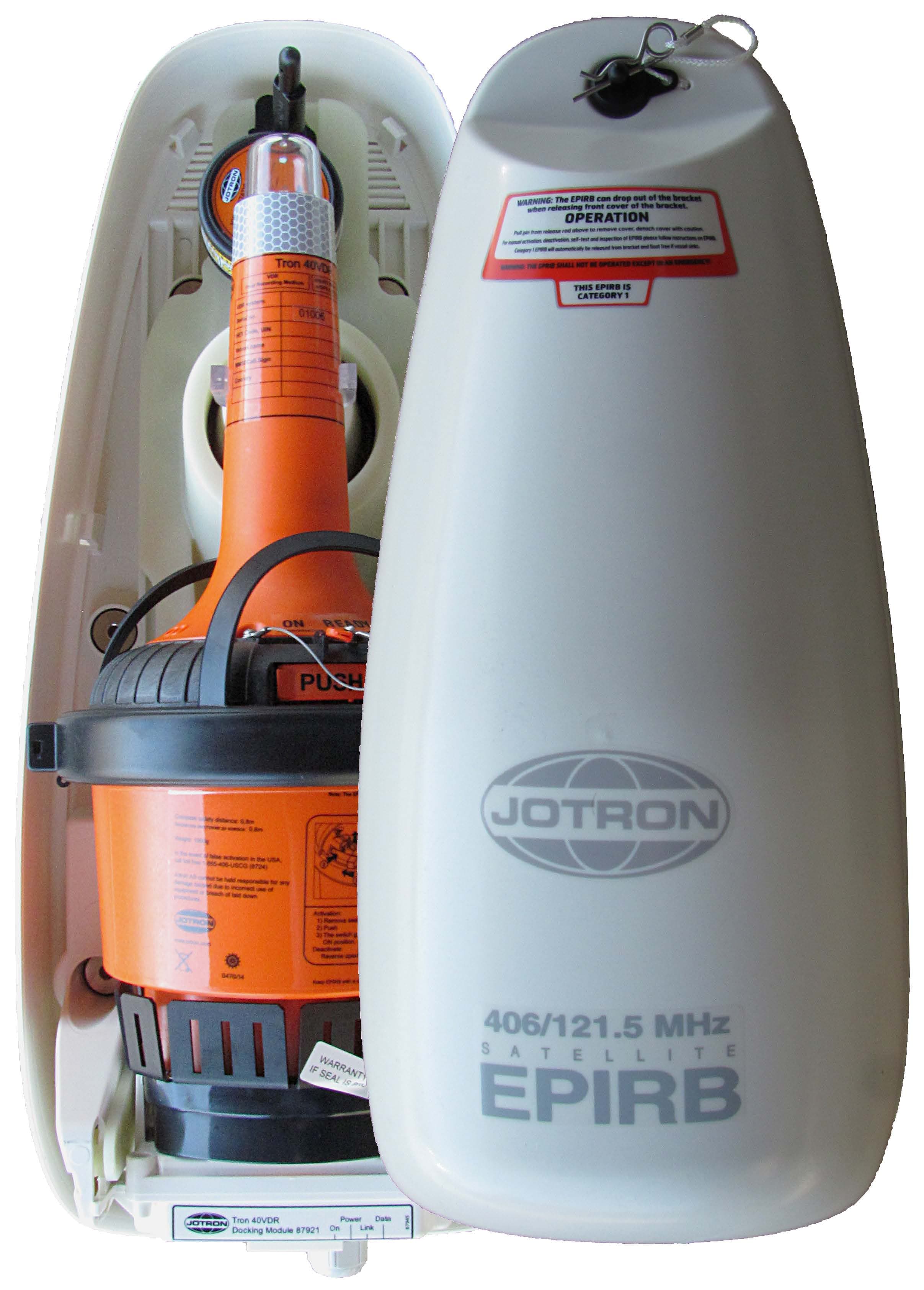
VRVTRON40VDR
Aug 30, 2015Float Free EPIRB with VDR
Equipment Class
GEP - 406 MHz EPIRB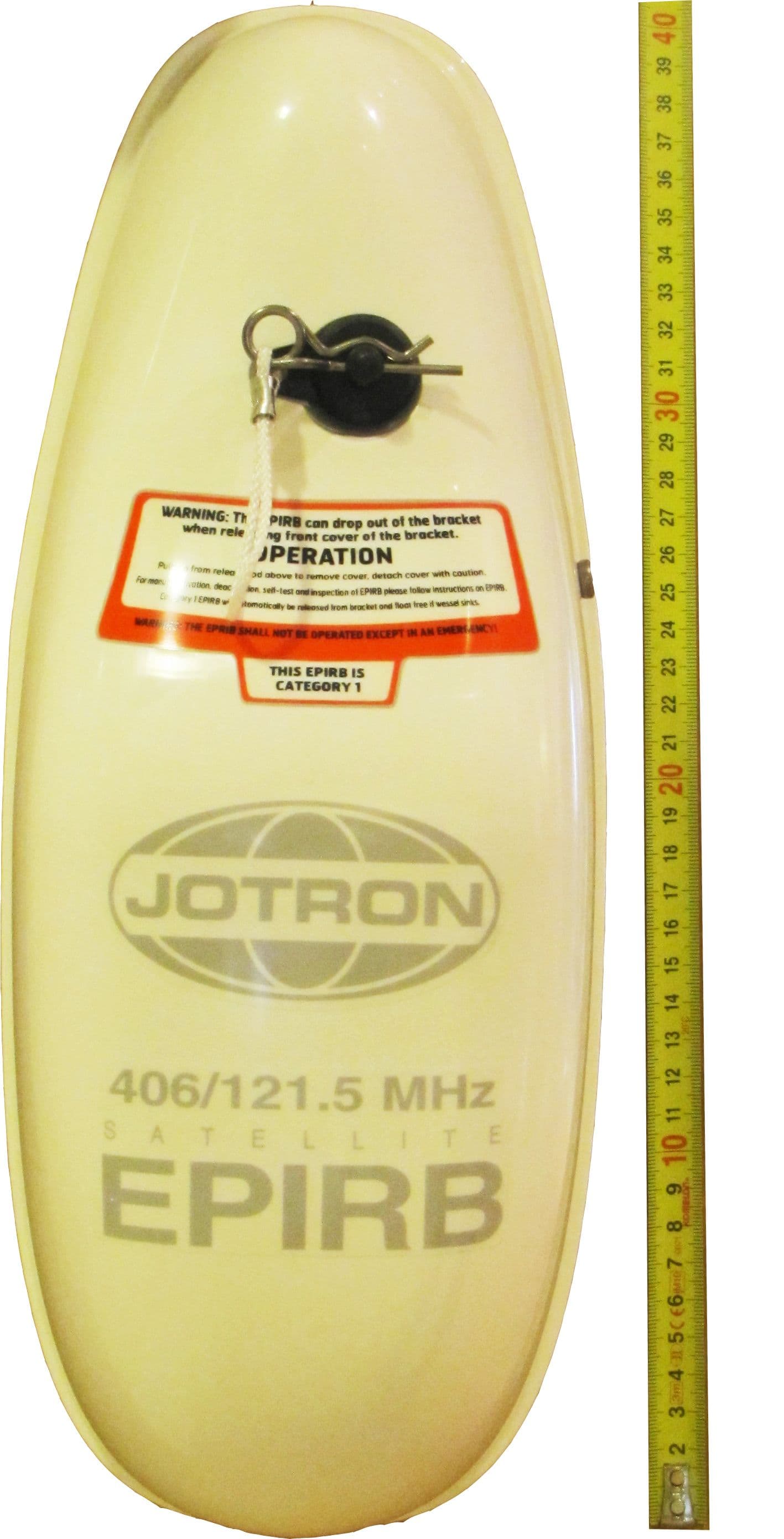
VRVTRON60GPS
Feb 12, 2013406 MHz EPIRB with GPS
Equipment Class
GEP - 406 MHz EPIRB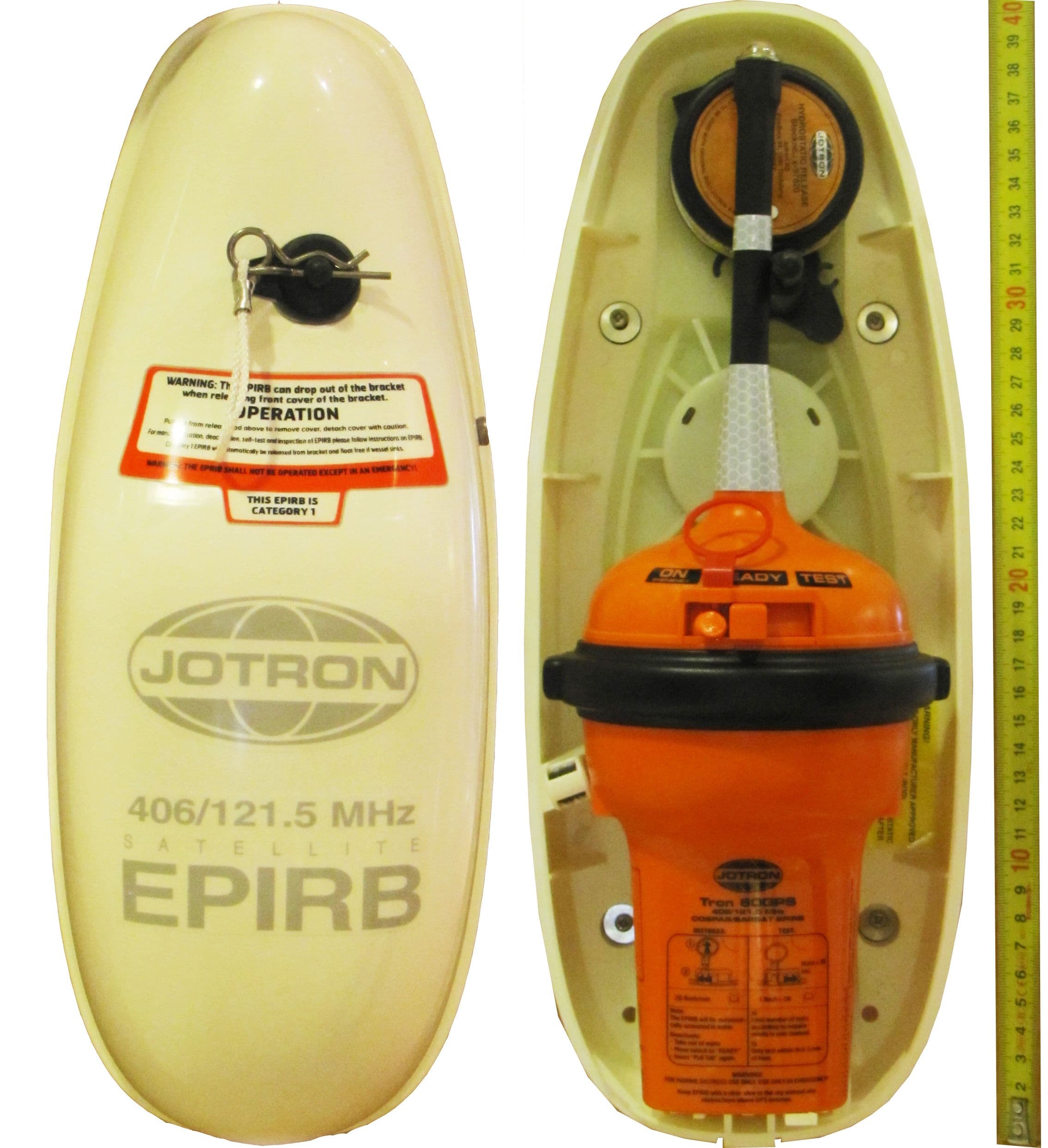
VRVTRON60S
Jan 01, 2013406 MHz EPIRB
Equipment Class
GEP - 406 MHz EPIRB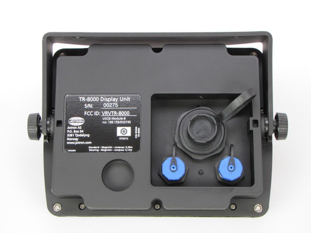
VRVTR8000
Oct 25, 2012Tron AIS TR-8000
Equipment Class
AIS - Automatic Identification Systems
VRVTRONS-VDR
Mar 19, 2008Protective Capsule for S-VDR and EPIRB
Equipment Class
GEP - 406 MHz EPIRB