VSOXM-4000AFM TRANSCEIVER
YEONHWA M TECH CO.,LTD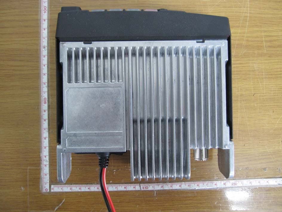
Click to zoom
Application Details
- Equipment Class
- TNB - Licensed Non-Broadcast Station Transmitter
- Date of Grant
- Jun 01, 2011
- Application Purpose
- Original Equipment
- Date of Application
- Jun 01, 2011
- Equipment Note
- FM TRANSCEIVER
- Frequency Range
- 406.10000000 - 470.00000000
- Company
- YEONHWA M TECH CO.,LTD
- Country
- South Korea
Documents & Files
Document Text
Text extracted from the exhibit documents filed with the FCC. Open a document above to read the original.
Users Manual
USERS MANUAL VHF Transceiver XM-1000 / XM-1200 UHF Transceiver XM-4000A / XM-4200A XM-4000B / XM-4200B * Version #1 (2011-05-16) 3F Yukyoung B/D, 544-6, Gasan-dong, Geumcheon-gu, Seoul, 153-803, Korea Table of Contents 1. Safety / Warnings 2. Feature 3. Appearance of XM Series Mobile Radio 4. Controls & keys 5. Menu Description 6. Terminal Description 7. Specification 1. Safety / Warnings Notices ◆ Government law restricts the operation of unlicensed radio transmitters within government controlled territories. ◆ Illegal operation is punishable by fine or imprisonment or both. ◆ Refer service to qualified technicians only. ◆ EXPLOSIVE ATMOSPHERES (GASES, DUST, FUMES, etc.) Shut OFF the transceiver while refueling or while parked in gasoline service stations. Do not carry spare fuel containers in the trunk of your vehicle if your transceiver is mounted in the trunk area ◆ INJURY FROM RADIO FREQUENCY TRANSMISSIONS Do not operate your transceiver when somebody is either touching the antenna or standing within two to three feet of it, to avoid the possibility of radio frequency burns or related physical injury. Precautions Please read carefully the following precautions to prevent fire, personal injury, or transceiver damage: Do not attempt to configure your transceiver while driving, it is dangerous. This transceiver is designed for a 13.8V DC power supply. Don't use a 24V battery including over DC 16V supply to power on the transceiver. Do not put the transceiver in excessively dusty, humid or wet areas, nor unstable surfaces. Do not modify the transceiver for any reason. Please keep it away from interferential devices (such as TV, generator, Medical devices etc.) Do not expose the transceiver to long periods of direct sunlight nor place it close to heating appliances. If an abnormal odor or smoke is detected coming from the transceiver, turn OFF the power immediately. Contact an Any tone service station or your dealer. Do not transmit with high output power for extended periods; the transceiver may overheat. Do not operate the transceiver when vehicle engine is stopped. The vehicle engine may not be started due to low battery. Do not use incompatible accessories from other manufactures. It could result in damage and or malfunction to the accessory and or to the radio. PREPARATION Various electronic equipment in your vehicle may malfunction if they are not properly protected form the radio frequency energy which is present while transmitting. Typical examples include electronic fuel injection, anti-skid braking and cruise control. If your vehicle contains such equipment, consult the dealer for the make of vehicle and enlist his/her aid in determining if they will perform normally while transmitting Power Cable Connection The transceiver operates in 12V negative ground system only! Check the battery polarity and voltage of vehicle before installing the transceiver. 1. Check for an existing hole, conveniently located in the firewall, where the power cable can be passed through. • If no hole exists, use a circle cutter to drill a hole, then install a rubber grommet 2. Run the power cable though the firewall and into the engine compartment. 3. Connect the red lead to the (+) battery terminal and the black lead to the negative (-) battery terminal •Place the fuse as close to the battery as possible 4. Coil the surplus cable and secure it with a retaining band. • Be sure to leave enough slack in the cables so the transceiver can be removed for servicing while keeping the power applied. RADIO FREQUENCY ENERGY SAFETY INFORMATION Your radio generates RF electromagnetic energy during transmit mode. This radio is designed for and classified as “Occupational Use Only”, meaning it must be used only during the course of employment by individuals aware of the hazards, and the ways to minimize such hazards. This radio is NOT intended for use by the “General Population” in an uncontrolled environment. This radio has been tested and complies with the FCC RF exposure limits for “Occupational Use Only”. In addition, your XRADIO radio complies with the following Standards and Guidelines with regard to RF energy and electromagnetic energy levels and evaluation of such levels for exposure to humans: ■ FCC OET Bulletin 65 Edition 97-01 Supplement C, Evaluating Compliance with FCC Guidelines for Human Exposure to Radio Frequency Electromagnetic Fields. ■ American National Standards Institute (C95.1-1992), IEEE Standard for Safety Levels with Respect to Human Exposure to Radio Frequency Electromagnetic Fields, 3 kHz to 300 GHz. ■ American National Standards Institute (C95.3-1992), IEEE Recommended Practice for the Measurement of Potentially Hazardous Electromagnetic Fields– RF and Microwave. ■ The following accessories are authorized for use with this product. Use of accessories other than those (listed in the instruction) specified may result in RF exposure levels exceeding the FCC requirements for wireless RF exposure. To ensure that your expose to RF electromagnetic energy is within the FCC allowable limits for occupational use, always adhere to the following guidelines: ■ DO NOT operate the radio without a proper antenna attached, as this may damaged the radio and may also cause you to exceed FCC RF exposure limits. A proper antenna is the antenna supplied with this radio by the manufacturer or antenna specifically authorized by the manufacturer for use with this radio. ■ DO NOT transmits for more than 50% of total radio use time (“50%duty cycle”). Transmitting more than 50% of the time can cause FCC RF exposure compliance requirements to be exceeded. The radio is transmitting when the “TX indicator” lights red. You can cause the radio to transmit by pressing the “PTT” switch. ■ ALWAYS keep the antenna at least 45 cm away from the body when transmitting and only use the Xradio belt-clip which is listed in instructions when attaching the radio to your belt, etc., to ensure FCC RF exposure comp…
Text truncated - open the document above for the full version.
Cover Letter(s)
3F, Yukyong B/D, 544-6, Gasan-dong, Geumcheon-gu, Seoul, Korea 153-803 May 19, 2011 Federal Communications Commission Equipment Authorization Branch 7435 Oakland Mills Road Columbia, MD 21046 LETTER OF AUTHORIZATION To whom it may concern: We, the undersigned, hereby authorize LTA Co., Ltd., to act on our behalf in all manners relating to application for equipment authorization for FCC ID: VSOXM-4000A including signing of all documents relating to these matters. Any and all acts carried out by LTA Co., Ltd., on our behalf shall have the same affect as acts of our own. This authorization is valid until further written notice from Yeonhwa M Tech Co., Ltd. LTA Co.,LTD. (Contact Person) Contact name: LEE, Kyung-Taek Position: Manager Phone:(82)31-323-6008 E-mail: [email protected] Sincerely, Hwan-Dae Kim / Chief Engineer Yeonhwa M Tech Co., Ltd.
Cover Letter(s)
3F, Yukyong B/D, 544-6, Gasan-dong, Geumcheon-gu, Seoul, Korea 153-803 May 18, 2011 Federal Communications Commission Equipment Authorization Branch 7435 Oakland Mills Road Columbia, MD 21046 In re : Yeonhwa M Tech Co., Ltd. FCC ID : VSOXM-4000A Request for Confidentiality Pursuant to Sections 0.457 and 0.459 of the Commission’s Rules (CFR 47), and Section 552 (b) (4) of the Freedom of Information Act, Yeonhwa M Tech Co., Ltd.. hereby requests confidentiality and treatment of certain information accompanying this application. The materials contain trade secrets and proprietary information not customarily released to the public. The public disclosure of these matters might be harmful to the Applicant and provide unjustified benefits to its competitors. We are also hereby request Short-Term Confidentiality for 180 days after the grant as outlined in Public Notice DA 04-1705. This provision will give Yeonhwa M Tech Co., Ltd.. temporary confidentiality of commercially sensitive information prior to product release. The requested Confidential and Temporary Confidential exhibits are listed as follows: Exhibit Type File Name Schematics CONF APPENDIX VSOXM-4000A SCH DIA.pdf Parts list CONF APPENDIX VSOXM-4000A PL.pdf Block diagram CONF APPENDIX VSOXM-4000A BLK DIA.pdf CONFIDENTIAL Operational description CONF APPENDIX VSOXM-4000A OpDes.pdf External Photos SHORT-TERM CONF VSOXM-4000A EXT Photo.pdf Internal Photos SHORT-TERM CONF VSOXM-4000A INT Photo.pdf Test-Setup Photos SHORT-TERM CONF VSOXM-4000A Test Photo.pdf SHORT-TERM CONFIDENTIAL User’s Manual SHORT-TERM CONF VSOXM-4000A Manual.pdf The Applicant understands that pursuant to Rule 0.457, disclosure of this application and all accompanying documentations, where applicable, will not be made public before the date of the Grant for this application. Sincerely, Hwan-Dae Kim / Chief Engineer Yeonhwa M Tech Co., Ltd.
Cover Letter(s)
3F, Yukyong B/D, 544-6, Gasan-dong, Geumcheon-gu, Seoul, Korea 153-803 May 18, 2011 Federal Communications Commission Equipment Authorization Branch 7435 Oakland Mills Road Columbia, MD 21046 In re : Yeonhwa M Tech Co., Ltd. FCC ID : VSOXM-4000A 90.203(e) and (g) statement request Gentlemen: This equipment meets the requirements of FCC Rules, Parts 90.203 (e) and (g) as applicable. Programming of this product's transmit frequencies can be performed ONLY by the manufacturer or by service or maintenance personnel. The operator cannot program transmit frequencies using the equipment's external operation. Sincerely, Hwan-Dae Kim / Chief Engineer Yeonhwa M Tech Co., Ltd.
Cover Letter(s)
3F, Yukyong B/D, 544-6, Gasan-dong, Geumcheon-gu, Seoul, Korea 153-803 May 18, 2011 Timco Engineering, Inc. 849 NW State Road 45 P.O. Box 370 Newberry, Florida 32669 Subject: FCC ID justification letter for expanded frequency range 400 - 470 MHz Gentlemen; The XM-4000A radio was designed to operate in the frequency bands 400 - 470 MHz To aid equipment authorization in other countries that accept the United States FCC Grant for Certification, Yeonhwa M Tech is requesting that the FCC list the frequencies 400 - 470 MHz under FCC Rule Parts 90 on the FCC Grant. For the FCC’s Rule Parts 90 applications, this radio is used in systems by Federal and Public Safety agencies including Police, Fire, and Emergency Medical Services, etc. as indicated in the table below. Frequencu Range (MHz) Part 90 Part 22 Part 74 Part 80 Federal Grant Notes 400-406 X EF, BE 406.1 – 410.0 X X EF, BE 410 – 420 X X EF, BE 450 – 454 X X EF, BE 454 – 455 X X EF, BE 455 - 456 X EF, BE 456 – 460 X X X EF, BE 460 – 462.5375 X EF, BE 462.7375 - 470 X EF, BE Equipment programming is the responsibility of Authorized Service Personnel. In addition, the radio complies with 47 CFR Part 90.203(e), in that the operator cannot directly program the transmit frequencies using the normally accessible external controls. Per the FCC’s KDB634817 guidance, “as an alternative to listing the exact frequencies, we acknowledge that it’s a violation of the FCC Rules if this device operates on unauthorized frequencies. Truly yours, Sincerely, Hwan-Dae Kim / Chief Engineer Yeonhwa M Tech Co., Ltd.
External Photos
FCC ID: VSOXM-4000A Copyright ○ c 2011, LTA Co., Ltd. Page 1 of 3 FCC ID: VSOXM-4000A Copyright ○ c 2011, LTA Co., Ltd. Page 2 of 3 FCC ID: VSOXM-4000A Copyright ○ c 2011, LTA Co., Ltd. Page 3 of 3
ID Label/Location Info
FCC ID: VSOXM-4000A Copyright Ⓒ 2011, LTA Co., Ltd. SAMPLE LABEL & LOCATION
Internal Photos
FCC ID: VSOXM-4000A Copyright ○ c 2011, LTA Co., Ltd. Page 1 of 2 FCC ID: VSOXM-4000A Copyright ○ c 2011, LTA Co., Ltd. Page 2 of 2
Parts List/Tune Up Info
3F, Yukyong B/D, 544-6, Gasan-dong, Geumcheon-gu, Seoul, Korea 153-803 TUNE-UP PROCEDURE Programming of this product's transmit frequencies can be performed ONLY by the manufacturer or by service or maintenance personnel. The operator cannot program transmit frequencies using the equipment's external operation.
RF Exposure Info
3F, Yukyong B/D, 544-6, Gasan-dong, Geumcheon-gu, Seoul, Korea 153-803 §1.1307 and §2.1093-RF EXPOSURE EVULATION 1.1 Limit § 1.1310: The criteria listed in the following table shall be used to evaluate the environmental impact of human exposure to radio-frequency (RF) radiation as specified in 1.1307(b). LIMITS FOR MAXIMUM PERMISSIBLE EXPOSURE (MPE) Frequency Range (MHz) Electric Field Strength (V/m) Magnetic Field Strength (A/m) Power Density (mW/cm2) Average Time (minutes) (A) Limits for Occupational/Control Exposures 30 - 300 61.4 0.163 1.0 6 300 - 1500 -- -- f/300 6 (B) Limits for General Population/Uncontrolled Exposure 30 - 300 27.5 0.073 0.2 30 300 - 1500 -- -- f/1500 30 Note: f is frequency in MHz 1.2 Method of Measurements Calculation Method of RF Safety Distance: Where, P: power input to the antenna in mW EIRP: Equivalent (effective) isotropic radiated power. S: power density mW/cm2 G: numeric gain of antenna relative to isotropic radiator r: distance to centre of radiation in cm FCC radio frequency exposure limits may be exceeded at distances closer than r cm from the antenna of this device . 1.3 Evaluation of RF Exposure Compliance Requirements Maximum RF Power conducted, P [dBm] = 46.04 Maximum Antenna Gain, G[dBi] = 0 Maximum EIRP, P [dBm] = 46.04 User-based time-average for PTT = 50% Peak EIRP = 46.04dBm + 0 dBi = 46.04 dBm = 40,170 mWatts (worst case) Average EIRP = 50% * EIRP = 20,085 mWatts MPE Limit for Occupational/Controlled Exposure, S [mW/cm2] = 1.0 MPE Limit for General Population/Uncontrolled Exposure, S [mW/cm2] = 0.2 Calculation of Minimum RF Safety Distance Limits: Calculated RF Safety Distance for Occupational/Controlled Exposure, r [cm] = 39.98 Calculated RF Safety Distance for General Population/Uncontrolled Exposure, r [cm] = 89.40 Results: Manufacturer declares RF Safety Distance of 40 cm for Occupational/Controlled Exposure and 90 cm for General Population/Uncontrolled Exposure which met the FCC Limits. Please refer to Users Manual for details of RF Exposure Information.
Test Report
Ref. No.: LR500111105F Copyright ○ c 2011, LTA Co., Ltd. Page 1 of 29 243 Jubug-Ri,Yangji-Myeon, Yongin-Si, Gyeonggi-Do, Korea 449-822 Tel: +82-31-323-6008 Fax: +82-31-323-6010 http://www.ltalab.com CERTIFICATION OF COMPLIANCE FCC ID. APPLICANT Device Category : VHF FM Transceiver Manufacturing Description : FM TRANSCEIVER Manufacturer : Yeonhwa M Tech Co., Ltd. Trade mark : Xradio Model name : XM-4000A Varient model name : XM-4200A Serial number : Identical prototype FCC Rule Part(s) : §2, §22, §74, §90 Frequency Range : 400 ~ 470MHz RF Output Power : 40W Channel Separation : 12.5kHz Emission Designators: : 10K4F3E Data of issue : May 20, 2011 This test report is issued under the authority of: The test was supervised by: Hyun-Chae You, Manager Il-Shin kim, Test Engineer This test result only responds to the tested sample. It is not allowed to copy this report even partly without the allowance of the test laboratory. The report must not be used by the client to claim product certification, approval, or endorsement by NVLAP, NIST, or any agency of the Federal Government. NVLAP LAB Code.: 200723-0 Dates of Tests : May 11~19, 2011 Test Report S/N : LR500111105F Test Site : LTA CO., LTD. VSOXM-4000A Yeonhwa M Tech Co., Ltd. Ref. No.: LR500111105F Copyright ○ c 2011, LTA Co., Ltd. Page 2 of 29 TABLE OF CONTENTS 1. GENERAL INFORMATION’S -------------------------------------------------------------------------- 2. INFORMATION’S ABOUT TEST ITEM ------------------------------------------------------------- 3. TEST REPORT --------------------------------------------------------------------------------------------- 3.1 SUMMARY OF TESTS ------------------------------------------------------------------------------- 3.2 REQUIREMENTS ------------------------------------------------------------------------------------- 3.2.1 CARRIER OUTPUT POWER (CONDUCTED) -------------------------------------------- 3.2.2 UNWANTED EMISSIONS (TRANSMITTER CONDUCTED) (CONDUCTED) ---- 3.2.3 FIELD STRENGTH OF SPURIOUS RADIATION ---------------------------------------- 3.2.4 EMISSION MASKS (OCCUPIED BANDWIDTH) ---------------------------------------- 3.2.5 TRANSIENT FREQUENCY BEHAVIOR --------------------------------------------------- 3.2.6 AUDIO FREQUENCY RESPONSE ----------------------------------------------------------- 3.2.7 MODULATION LIMITING --------------------------------------------------------------------- 3.2.8 FREQUENCY STABILITY (TEMPERATURE VARIATION) ----------------------------- 3.2.9 FREQUENCY STABILITY (VOLTAGE VARIATION) ------------------------------------- 3.2.10 NECESSARY BANDWIDTH AND EMISSION BANDWIDTH ------------------------ APPENDIX APPENDIX I TEST EQUIPMENT USED FOR TESTS --------------------------------------------- APPENDIX II TEST PLOTS ----------------------------------------------------------------------------- 3 4 5 5 6 6 7 10 12 13 14 15 16 17 18 19 21 Ref. No.: LR500111105F Copyright ○ c 2011, LTA Co., Ltd. Page 3 of 29 1. General information’s 1-1 Test Performed Company name : LTA Co., Ltd. Address : 243, Jubug-ri,Yangji-Myeon,Youngin-Si, Kyunggi-Do, Korea. 449-822 Web site : http://www.ltalab.com E-mail : [email protected] Telephone : +82-31-323-6008 Facsimile : +82-31-323-6010 Quality control in the testing laboratory is implemented as per ISO/IEC 17025 which is the “General requirements for the competents of calibration and testing laboratory”. 1-2 Accredited agencies LTA Co., Ltd. is approved to perform EMC testing by the following agencies: Agency Country Accreditation No. Validity Reference NVLAP U.S.A 200723-0 2011-09-30 ECT accredited Lab. KCC KOREA KR0049 2013-04-24 EMC accredited Lab. FCC U.S.A 610755 2014-04-27 FCC filing FCC U.S.A 649054 2011-05-26 FCC CAB VCCI JAPAN R-2133, C-2307 2011-06-21 VCCI registration VCCI JAPAN T-2009 2013-12-23 VCCI registration IC CANADA 5799A 2012-05-14 IC filing Ref. No.: LR500111105F Copyright ○ c 2011, LTA Co., Ltd. Page 4 of 29 2. Information’s about test item 2-1 Client & Manufacturer Company name : Yeonhwa M Tech Co., Ltd. Address : 3F, Yukyong B/D, 544-6, Gasan-dong, Geumcheon-gu, Seoul, Korea TEL / FAX : +82-70-7434-7274 / +82-2-3281-7271 2-2 Equipment Under Test (EUT) Trade name : VHF FM Transceiver FCC ID : VSOXM-4000A Model name : XM-4000A Varient model name : XM-4200A Serial number : Identical prototype Date of receipt : May 11, 2011 EUT condition : Pre-production, not damaged Frequency Range : 400 ~ 470 MHz RF output power : 40W Channel Separation : 12.5kHz Duty cycle TX power : 5(Tx) : 5(Rx) : 90(Stand-by) Speaker Impedance : 16 ohm Audio Output Power : 1.0Watt across an 16-ohm load Power Source : 13.8V DC 2-3 Tested frequency LOW MID HIGH Frequency (MHz) 406.125 435.025 469.975 2-4 Ancillary Equipment Equipment Model No. Serial No. Manufacturer MIC MM-100 N/A N/A CAR BATTERY BX40R N/A ATLASBX Ref. No.: LR500111105F Copyright ○ c 2011, LTA Co., Ltd. Page 5 of 29 3. Test Report 3.1 Summary of tests FCC Part Section(s) Parameter Status (note 1) 2.1046 (a) Carrier Output Power (Conducted) C 2.1051 Unwanted Emissions (Transmitter Conducted) C 2.1053 (a) Field Strength of Spurious Radiation C 2.1049 (c) (1) Emission Masks (Occupied Bandwidth) C 90.214 Transient Frequency Behavior C 2.1047 (a) Audio Low Pass Filter (Voice Input) C 2.1047 (a) Audio Frequency Response C 2.1047 (b) Modulation Limiting C 2.1055 (a) (1) Frequency Stability (Temperature Variation) C 2.1055 (b) (1) Frequency Stability (Voltage Variation) C 2.202 (g) Necessary Bandwidth and Emission Bandwidth C Note 1: C=Complies NC=Not Complies NT=Not Tested NA=Not Applicable The sample was tested according to the following specification: *FCC Rules and Regulations, Volume II; Part 2, Sub-part J, Sections 2.947, 2.1033(c), 2.1046, 2.1047, 2.1079, 2.1051, 2.1053, 2.1055, 2.1057 and Part 22, Part 74 Subpart H, Part 90. *ANSI C63.4 *TIA/EIA 603, Edition C Ref. No.: LR500111105F Copyright ○ c 2011, LTA Co., Ltd. Page 6 of 29 3.2 Transmitter requirements 3.2.1 Carrier Output Power…
Text truncated - open the document above for the full version.
Test Setup Photos
FCC ID: VSOXM-4000A Copyright Ⓒ 2011, LTA Co., Ltd. Page 1 of 1 Radiated Emission
Contact Information
Applicant
HWAN-DAE KIM
Test Firm
LTA Co.,LtdAhn Chulho
Technical Specifications
| # | Rule Parts | Frequency Range | Power Output | Emission | Tolerance |
|---|---|---|---|---|---|
| 2 | 9 | 406.1 MHz - 470 MHz | 40 W | 10K4F3E | 2.5 ppm |
Other Applications from YEONHWA M TECH CO.,LTD
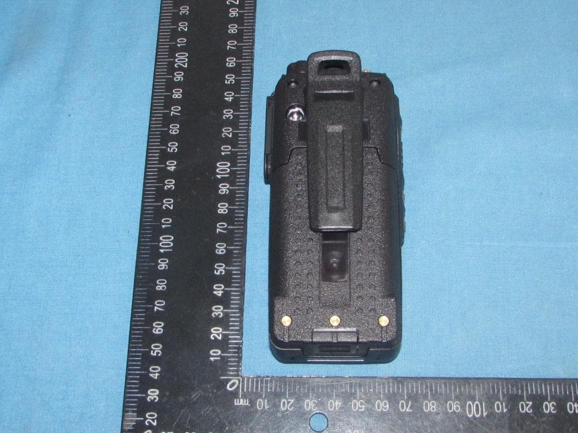
VSODX-7100
Jul 16, 2023Digital 5W Portable Radio
Equipment Class
TNF - Licensed Non-Broadcast Transmitter Held to Face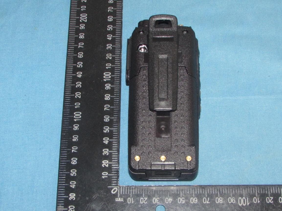
VSODX-7400
Jul 16, 2023Digital 5W Portable Radio
Equipment Class
TNF - Licensed Non-Broadcast Transmitter Held to Face
VSODX-300
Jul 16, 2023Digital 2W Portable Radio
Equipment Class
TNF - Licensed Non-Broadcast Transmitter Held to Face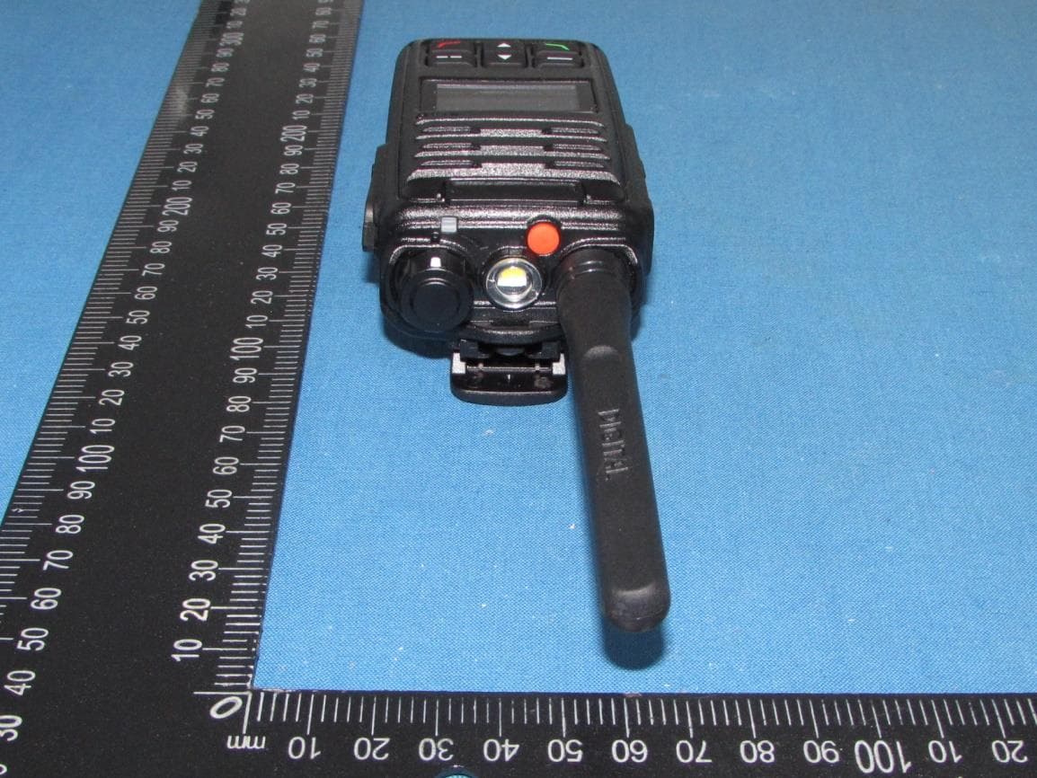
VSODX-5400
Sep 12, 2021Digital 5W Portable Radio
Equipment Class
TNF - Licensed Non-Broadcast Transmitter Held to Face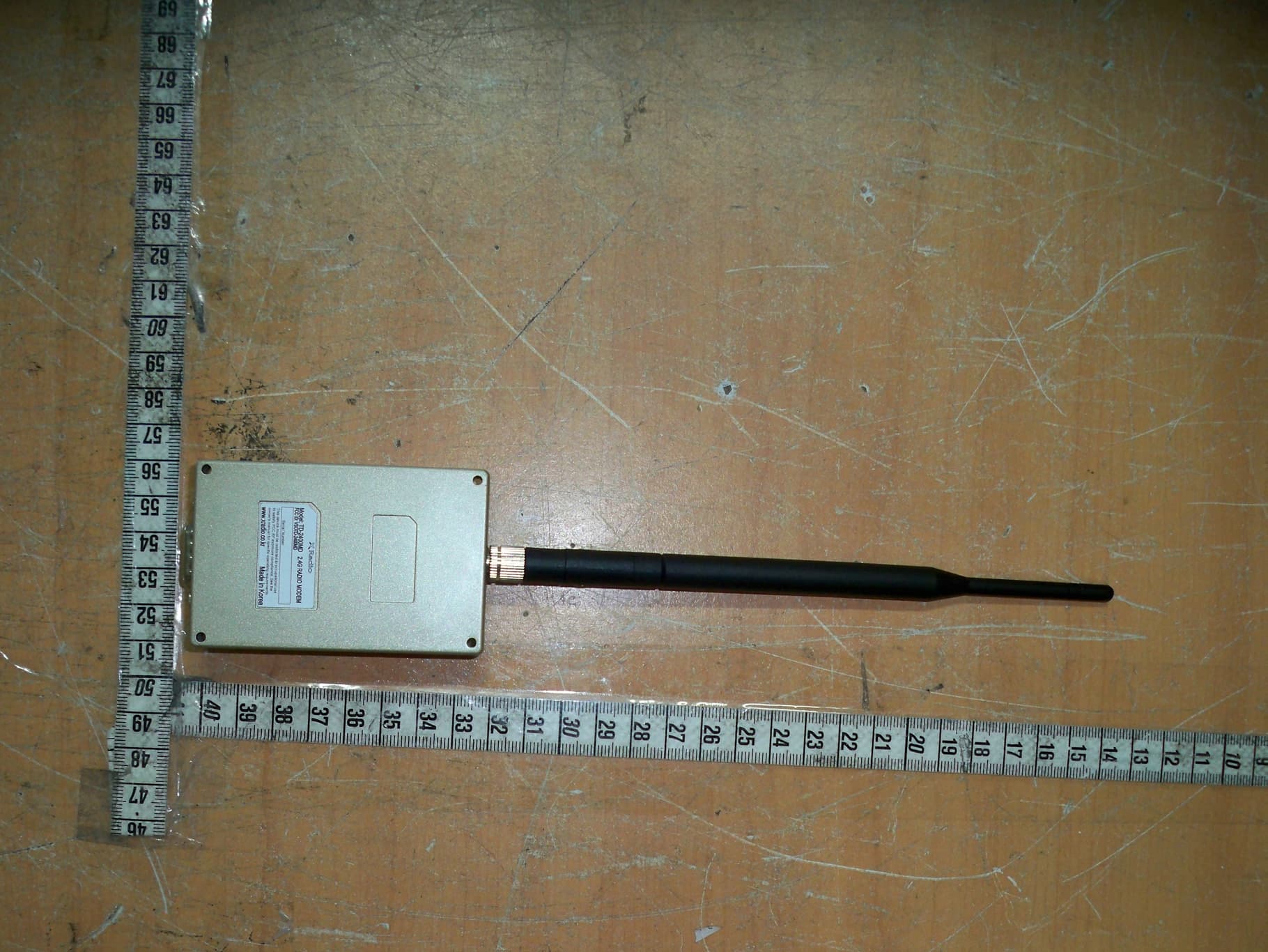
VSOTD-2400MD
Apr 29, 2013Zigbee Data Modem Module
Equipment Class
DTS - Digital Transmission System