VSOXR-450FM TRANSCEIVER
YEONHWA M TECH CO.,LTD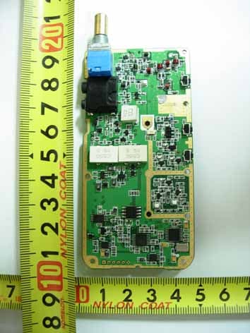
Click to zoom
Application Details
- Equipment Class
- TNF - Licensed Non-Broadcast Transmitter Held to Face
- Date of Grant
- Dec 15, 2009
- Application Purpose
- Original Equipment
- Date of Application
- Dec 14, 2009
- Equipment Note
- FM TRANSCEIVER
- Frequency Range
- 406.10000000 - 500.00000000
- Company
- YEONHWA M TECH CO.,LTD
- Country
- South Korea
Documents & Files
Document Text
Text extracted from the exhibit documents filed with the FCC. Open a document above to read the original.
Users Manual
XR-150/XR-450 Portable Radio Manual * This Service manual is subject to change according to improvement of XR-150/XR-450 Portable Radio without notice. * Version #2 (2009-06-09) 2 Table of Contents 1. Features ------------------------------------------ 3 2. Components of XR-150/XR-450 Series Radio ---------------------- 4 3. Appearance of XR-150/XR-450 Series Radio -------------------- 5 4. Basic Operation of XR-150/XR-450 Series Radio -------------------- 6 4.1 Installation and Removing the Antenna ---------------------- 6 4.2 Installation and Removing the Battery ---------------------- 7 4.3 Installation and Removing the Belt Clip --------------------- 7 4.4 Accessory Connector ------------------------------- 8 4.5 Operating XR-150/XR-450 Radio -------------------------------- 8 5. Charging the Battery ------------------------------- 9 6. Operating Instructions of XR-150/XR-450 Series Radio ----------- 11 7. Precautions ------------------------------- 24 8. Safety Notes -------------------------------- 25 9. Specification -------------------------------- 26 9.1 XR-150 --------------------------------- 26 9.3 XR-450 --------------------------------- 27 Thank you for your purchase of the XR-150/XR-450 Series Radio. 1. When using the Radio, please read the enclosed user guide in details. 2. The functions and specifications are subject to be changed without notice for improvement of the Radio performance. 3 1. Feature The XR-150/XR-450 series Radio is developed to be user-friendly and compact design, to have various features and to use at the construction / industrial / public areas for the safety & convenience of users. The followings are the main features of the XR-150/XR-450 Series Radio. 16Groups and 512Channels are selectable. Call guard Squelch of standardized 53 CTCSS / 208 DCS Frequency inverter type of Scramble function Compander function Dual Tone Modulation Frequency (DTMF) Normal Scan / Priority Scan Advanced Speaker Protection technology VOX (Voice Operated Transmit) BCL (Busy Channel Lock)/BCLO (Busy Channel Lock Out) Time-Out Timer (TOT) High/Low RF Power Selectable 2 Tone /5 Tone Monitor Emergency/Siren 5 step Squelch control using RSSI. Lone Worker Remote Radio Stun / Revive(Use 5 tone) High-Quality Audio Output(Ø40 Speaker) PLL synthesizer type Signal Strength Meter Battery Status Indicator PC Program Tuning USB PC Programming Various Parameters and PC downloading methods DC+7.5V Li-ion/ 2,200 mAH high capacity Battery 4 2. Components of XR-150/XR-450 Series Radio * Components could be changed by buyer request. Figure 3-1) standard components of XR-150/XR-450 series Radio 5 3. Appearance of XR-150/XR-450 Series Radio Figure 3-1) Appearance of XR-150/XR-450 Series Radio 6 Figure 3-2) XR-150/XR-450 Series LCD Indication 4. Basic Operation of XR-150/XR-450 Series Radio Pease read this manual carefully before using XR-150/XR-450 series Radio. This manual contains important information about using Radio. 4.1 Installation and Removing the Antenna To install the antenna, insert the antenna into antenna connector and screw the antenna clockwise. To remove the antenna, screw the antenna counter clockwise. Figure 4-1) Installation and Removing the Antenna When installation of the antenna, giving a strong pressure to the Radio or pulling the antenna with a strong power from the Radio can make a damage on the antenna connector, which may cause the Radio to have a critical problem. 7 4.2 Installation and Removing the Battery 4.2.1 Installation of the battery -. To install battery, slide up the battery towards the top of the radio until battery latch is locked. 4.2.2 Removing the Battery -. Slide the battery latch located on the bottom of radio to the open position as shown in Figure 4-2. -. The battery is removed by pressing it against and sliding it towards the bottom of the radio Figure 4-2) Installation and Removing the Battery 4.3 Installation and Removing the Belt Clip - To attach belt clip to radio, align belt clip rails with the grooves in radio and slide the belt clip onto the mounting rails until it latches into place. - To remove belt clip from radio, push up on tab of belt clip with flat bladed screw driver and at the same time, slide the belt clip towards the top of Radio figure 4-3). Figure 4-3) Installation and Removing the Belt Clip 8 4.4 Accessory connector Accessory connector is used to connect external speaker Mic, and headset, etc. Please close the cover when nothing is connected. Figure 4-4) Accessory connector 4.5 Operating XR-150/XR-450 RADIO 4.5.1 ON/OFF/Volume Control Turns the radio on and off and adjusts audio volume level. 4.5.2 PTT Button(Push-To-Talk Button) You can transmit by pressing PTT button. DTMF or 5-Tone ID is transmitted according to Transceiver setting. At this moment, you can’t transmit your voice. And then Red LED will be ON and your voice will be transmitted. ☞ Note) In case of setting BCLO and TOT function, the transmission will be restricted for other users when you transmit continuously. 4.5.3 Menu Button(P, Program Menu Button) Enter into Menu mode by pressing the Menu button (P) for 2 seconds. The sequence of menu mode is as follows. → → → → Compander → Change Group → ID → Scramble → Squelch → → → → → KEY Sound → VOX → Lone Worker → Repeater 4.5.4 Monitor Button(M) The monitor mode is enabled and disabled by pressing the Monitor button (M) on the side. Normal Mode : During pressing the (M) button for about 2 seconds, it is possible to check the receiving status. Continuous Mode : During pressing the (M) button for more than 2 seconds, the Radio will make a “Beep” tone, which means the monitor function is maintained and if you press the (M) button again, the monitor function will be released. 9 4.5.5 Emergency Button In case of emergency situation, if you press the Emergency button, a siren sound will be heard through the speaker in the Radio and the Radio will transmit the emergency signa…
Text truncated - open the document above for the full version.
Cover Letter(s)
November 17, 2009 Federal Com munications Commission Equipment Authorization Branch 7435 Oakland Mills Road Columbia, MD 21046 LETTER OF AUTHORIZATION To whom it may concern: We, the undersigned, hereby authorize LTA Co., Ltd., to act on our behalf in all manners relating to application for equipment authorization for FCC ID: VSOXR-450 including signing of all documents relating to these matters. Any and all acts carried out by LTA Co., Ltd., on our behalf shall have the same affect as acts of our own. This authorization is valid until further written notice from Yeonhwa M Tech Co., Ltd. LTA Co.,LTD. (Contact Person) Contact name: LEE, Kyung-Taek Position: Manager Phone:(82)31-323-6008 E-mail: [email protected] Sincerely, Hwan-Dae Kim / Chief Engineer Yeonhwa M Tech Co., Ltd.
Cover Letter(s)
November1 7, 2009 Federal Co mm unications Commission Equipment Authorization Branch 7435 Oakland Mills Road Columbia, MD 21046 In re : Yeonhwa M Tech Co., Ltd. FCC ID : VSOXR-450 Request for Confidentiality Gentlemen: Pursuant to Sections 0.457 and 0.459 of the Commission’s Rules, we hereby request confidential treatment of information accompanying this application as outlined below: Exhibit Type File Name Schematics CONF APPENDIX VSOXR-450 SCH DIA.pdf Parts list CONF APPENDIX VSOXR-450 PL.pdf Block diagram CONF APPENDIX VSOXR-450 BLK DIA.pdf Operational description CONF APPENDIX VSOXR-450 OpDes.pdf The above materials contain trade secrets and proprietary information not customarily released to the public. The public disclosure of these materials may be harmful to the applicant and provide unjustified benefits to its competitors. The applicant understands that pursuant to Section 0.457 of the Rules, disclosure of this application and all accompanying documentation will not be made before the date of the Grant for this application. Sincerely, Hwan-Dae Kim / Chief Engineer Yeonhwa M Tech Co.,Ltd.
Cover Letter(s)
Noverber 17, 2009 Federal Co mm unications Commission Equipment Authorization Branch 7435 Oakland Mills Road Columbia, MD 21046 Cover letter FCC ID : VSOXR-450 Gentlemen: Yeonhwa M Tech requires the Part 90 FCC grant list frequencies outside of Part 90 assignments because state and local government users specify operation outside of Part 90 so that they can int eroperate with Federal agencies. The issue being that user ’s that are not under NTIA frequency coordi nation must use radios that have FCC approval. Sincerely, Hwan-Dae Kim / Chief Engineer Yeonhwa M Tech Co.,Ltd.
Cover Letter(s)
November 17, 2009 Federal Com munications Commission Equipment Authorization Branch 7435 Oakland Mills Road Columbia, MD 21046 In re : Yeonhwa M Tech Co., Ltd. FCC ID : VSOXR-450 90.203(e) and (g) statement request Gentlemen: This equipment meets the requirements of FCC Rules, Parts 90.203 (e) and (g) as applicable. Programming of this product's transmit frequencies can be performed ONLY by the manufacturer or by service or maintenance personnel. The operator cannot program transmit frequencies using the equipment's external operation. Sincerely, Hwan-Dae Kim / Chief Engineer Yeonhwa M Tech Co.,Ltd.
Cover Letter(s)
3F, Yukyong B/D, 544-6, Gasan-dong, Geumcheon-gu, Seoul, Korea 153-803 November 17, 2009 Timco Engineering, Inc. 849 NW State Road 45 P.O. Box 370 Newberry, Florida 32669 Subject: FCC ID justification letter for expanded frequency range 400-500 MHz Gentlemen; You have asked Yeonhwa M Tech Co., LTD. for justification to have the 400-5 00 MHz freq range appear on he face of the FCC Grant of Certification for a Part 90 Certification. This frequency range is regarded as usual & customary by United States Federal Government and its various departments, user organizations and the military to appear on the face of the equipment Grant of Certification. (1) Yeonhwa M Tech’s Marketing Departm ent plans to ensure that USA users, other than those specifically identified in this letter, not operate within bands 400-406.1 MHz, as controlled by the users’ FCC station license. (2) This device will not be m arketed to USA users, other than those identified in the letter, namely the US Government and its various departm ents & military, for operation in 400-406.1 MHz frequency range. Truly yours, Hwan-Dae Kim / Chief Engineer Yeonhwa M Tech Co.,Ltd.
External Photos
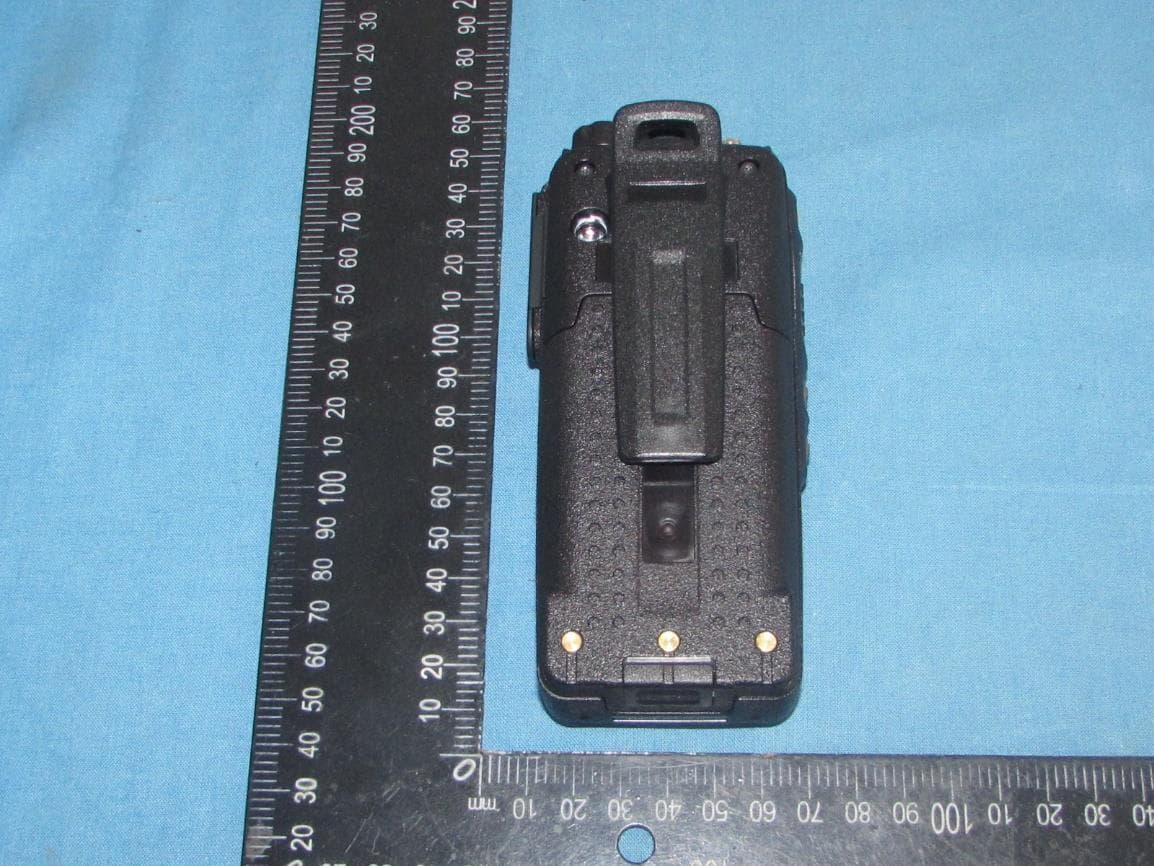
FCC ID: VSOXR-450 Copyright c 2009, LTA Co., Ltd. Page 1 of 3 FCC ID: VSOXR-450 Copyright c 2009, LTA Co., Ltd. Page 2 of 3 FCC ID: VSOXR-450 Copyright c 2009, LTA Co., Ltd. Page 3 of 3
ID Label/Location Info
November 17, 2009 Federal Co mm unications Co mmission Equipment Authorization Branch 7435 Oakland Mills Road Columbia, MD 21046 In re : Yeonhwa M Tech Co., Ltd. FCC ID : VSOXR-450 Label Information Gentlemen: Because The device is so small that it is not practicable to place the statem ent specified under 15.19 statement request, the information required by this paragraph shall be placed in a prominent location in the user's manual. Æ The available label area on the device is limited because it is relatively small and has many contoured surfaces, keypads, LDC displays, charge contacts and other connectors. Æ The batter ies are desig ned for easy removal and the label will be visible whenever the batteries are removed for charging or replacement. Æ The label will be readily visible at the time of purchase because the device will be marketed without the battery installed. Sincerely, Hwan-Dae Kim / Chief Engineer Yeonhwa M Tech Co.,Ltd. SAMPLE LABEL & LOCATION Note: 1. The label generally is located underneath a back door of the phone. 2. Beca use T he de vice is so sm all that it is not practicable to place the statem ent s pecified under 15.1 9 statement request, the information required by this paragraph shall be placed in a prominent location in the user's manual.
Internal Photos
FCC ID: VSOXR-450 Copyright c 2009, LTA Co., Ltd. Page 1 of 1
Parts List/Tune Up Info
3F, Yukyong B/D, 544-6, Gasan-dong, Geumcheon-gu, Seoul, Korea 153-803 TUNE-UP PROCEDURE Programming of this product's transmit frequencies can be performed ONLY by the manufacturer or by service or maintenance personnel. The operator cannot program transmit frequencies using the equipment's external operation.
RF Exposure Info
Report File No. : F690501/RF-SAR001852 Date of Issue : 2009-12-11 Page : 1 / 53 SAR TEST REPORT Equipment Under Test : FM Handheld Transceiver Model No. : XR-450 Applicant : Yeonhwa M Tech Co., Ltd. Address of Applicant : 3F, Yukyong B/D, 544-6, Gasan-dong, Geumcheon-gu, Seoul, Korea FCC ID : VSOXR-450 Device Category : Portable Device Exposure Category : Occupational/Controlled Exposure Date of Receipt : 2009-12-04 Date of Test(s) : 2009-12-04 Date of Issue : 2009-12-11 Max. SAR : 2.155 W/kg (Head 50% Duty Cycle) 6.20 W/kg (Body 50 % Duty Cycle) Standards: FCC OET Bulletin 65 supplement C IEEE 1528, 2003 ANSI/IEEE C95.1, C95.3 In the configuration tested, the EUT complied with the standards specified above. Remarks: Tested by : Fred Jeong 2009-12-11 Approved by : Charles Kim 2009-12-11 This report details the results of the testing carried out on one sample, the results contained in this test report do not relate to other samples of the same product. The manufacturer should ensure that all products in series production are in conformity with the product sample detailed in this report. This report may only be reproduced and distributed in full. If the product in this report is used in any configuration other than that detailed in the report, the manufacturer must ensure the new system complies with all relevant standards. Any mention of SGS Testing Korea Co., Ltd. or testing done by SGS Testing Korea Co., Ltd. in connection with distribution or use of the product described in this report must be approved by SGS Testing Korea Co., Ltd. in writing. Report File No. : F690501/RF-SAR001852 Date of Issue : 2009-12-11 Page : 2 / 53 Contents 1. General Information 1.1 Testing Laboratory........................................................................................... 3 1.2 Details of Applicant.......................................................................................... 3 1.3 Version of Report............................................................................................. 3 1.4 Description of EUT(s)....................................................................................... 3 1.5 Test Environment............................................................................................. 3 1.6 Model Description........................................................................................... 4 1.7 Operation description........................................................................................ 4 1.8 Evaluation procedures....................................................................................... 5 1.9 The SAR Measurement System............................................................................ 6 1.10 System Components.......................................................................................... 8 1.11 SAR System Verification.................................................................................... 9 1.12 Tissue Simulant Fluid for the Frequency Band.......................................................... 11 1.13 Test Standards and Limits.................................................................................. 12 2. Instruments List.................................................................................... 14 3. Summary of Results................................................................................ 15 APPENDIX A. Photographs of EUT & EUT’s Test Setup B. DASY4 SAR Report C. Uncertainty Analysis D. Calibration certificate Report File No. : F690501/RF-SAR001852 Date of Issue : 2009-12-11 Page : 3 / 53 1. General Information 1.1 Testing Laboratory SGS Testing Korea Co., Ltd. Wireless Div. 2FL, 18-34, Sanbon-dong, Gunpo-si, Gyeonggi-do, Korea 435-040 Telephone : +82 +31 428 5700 FAX : +82 +31 427 2371 Homepage : www.electrolab.kr.sgs.com 1.2 Details of Manufacturer Manufacturer : Yeonhwa M Tech Co., Ltd. Address : 3F, Yukyong B/D, 544-6, Gasan-dong, Geumcheon-gu, Seoul, Korea Contact Person : Hwan-Dae Kim Phone No. : 82-70-7434-7274 Fax No. : 82-2-3281-7271 1.3 Version of Report Version Number Date Revision 00 2009-12-11 Initial issue 1.4 Description of EUT(s) EUT Type : FM Handheld Transceiver Model : XR-450 Varient Model : XR-450T, XR-450M, XR-450R, XR-450G Serial Number : N/A Mode of Operation : LMR Body worn Accessory : Belt Clip Tx Frequency Range : 400.050 MHz ~ 499.975 MHz Antenna : λ/4 Whip Antenna Max. Conducted RF Power : 4.31 W (36.34 dBm) Battery Type : DC 7.5 V (Li-NH Battery) 1.5 Test Environment Ambient temperature : 22 ~ 23 ° C Tissue Simulating Liquid : 22 ~ 23 ° C Relative Humidity : 40 ~ 60 % Report File No. : F690501/RF-SAR001852 Date of Issue : 2009-12-11 Page : 4 / 53 1.6 Model Description Model No. Difference XR-450T Same RF Circuit, Graphic LCD, Multy Connector Type audio jack XR-450M Same RF Circuit, Graphic LCD, Multy Connector Type audio jack XR-450R Same RF Circuit, No LCD, Rotary switch, two pin connector Type audio jack XR-450G Same RF Circuit, No LCD, Rotary switch, Multy connector Type audio jack 1.7 Operation Configuration Reference Positions for Handheld Radio Transmitters In general handheld radio transmitters like GMRS/FRS/LMR devices are used in held to face position or with a speaker/microphone combination as body-worn configuration. Held to face position For held to face position the flat section of a SAM Phantom or a flat phantom is used. The center of the radiating structure is to set on the middle position of the flat phantom. The distance between sample and flat phantom is 2.5 cm, similar to the real using. For the measurement head tissue simulating liquid is used. Belt Clip/Holster Configuration Test configurations for body-worn operated EUTs are carried out while the belt-clip and/or holster is attached to the EUT and placed against a flat phantom in a regular configuration. An EUT with a headset output it tested with a headset connected to the device. Body dielectric parameters are used. There are two categories for acce…
Text truncated - open the document above for the full version.
Test Report
Ref. No.: LR500190911H Copyright ○ c 2009, LTA Co., Ltd. Page 1 of 36 243 Jubug-Ri,Yangji-Myeon, Yongin-Si, Gyeonggi-Do, Korea 449-822 Tel: +82-31-323-6008 Fax: +82-31-323-6010 http://www.ltalab.com CERTIFICATION OF COMPLIANCE FCC ID. APPLICANT Device Category : FM Handheld Transceiver Manufacturing Description : FM TRANSCEIVER Manufacturer :Yeonhwa M Tech Co., Ltd. Trade mark : XRadio Model name : XR-450 Varient model name XR-450T, XR-450M, XR-450R, XR-450G Serial number : Identical prototype FCC Rule Part(s) : §2, §22, §74, §90 Frequency Range : 400 ~ 500MHz RF Output Power : 4W / 2W Channel Separation : 12.5kHz / 25.0kHz Emission Designators: : 10K3F3E, 15K0F3E Data of issue : November 27, 2009 This test report is issued under the authority of: The test was supervised by: Dong –Min JUNG, Technical Manager Kyung-Taek LEE, Test Engineer This test result only responds to the tested sample. It is not allowed to copy this report even partly without the allowance of the test laboratory. This report must not be used by the applicant to claim product endorsement by any agency. NVLAP LAB Code.: 200723-0 Dates of Tests: October 3 ~ November 27, 2009 Test Report S/N: LR500190911H Test Site : LTA CO., LTD. VSOXR-450 Yeonhwa M Tech Co., Ltd. Ref. No.: LR500190911H Copyright ○ c 2009, LTA Co., Ltd. Page 2 of 36 TABLE OF CONTENTS 1. GENERAL INFORMATION’S -------------------------------------------------------------------------- 2. INFORMATION’S ABOUT TEST ITEM ------------------------------------------------------------- 3. TEST REPORT --------------------------------------------------------------------------------------------- 3.1 SUMMARY OF TESTS ------------------------------------------------------------------------------- 3.2 REQUIREMENTS ------------------------------------------------------------------------------------- 3.2.1 CARRIER OUTPUT POWER (CONDUCTED) -------------------------------------------- 3.2.2 UNWANTED EMISSIONS (TRANSMITTER CONDUCTED) (CONDUCTED) ---- 3.2.3 FIELD STRENGTH OF SPURIOUS RADIATION ---------------------------------------- 3.2.4 EMISSION MASKS (OCCUPIED BANDWIDTH) ---------------------------------------- 3.2.5 TRANSIENT FREQUENCY BEHAVIOR --------------------------------------------------- 3.2.6 AUDIO FREQUENCY RESPONSE ----------------------------------------------------------- 3.2.7 MODULATION LIMITING --------------------------------------------------------------------- 3.2.8 FREQUENCY STABILITY (TEMPERATURE VARIATION) ----------------------------- 3.2.9 FREQUENCY STABILITY (VOLTAGE VARIATION) ------------------------------------- 3.2.10 NECESSARY BANDWIDTH AND EMISSION BANDWIDTH ------------------------ APPENDIX APPENDIX I TEST EQUIPMENT USED FOR TESTS --------------------------------------------- APPENDIX II TEST PLOTS ----------------------------------------------------------------------------- 3 4 5 5 6 6 7 11 13 14 15 16 17 18 19 20 23 Ref. No.: LR500190911H Copyright ○ c 2009, LTA Co., Ltd. Page 3 of 36 1. General information’s 1-1 Test Performed Company name : LTA Co., Ltd. Address : 243, Jubug-ri,Yangji-Myeon,Youngin-Si, Kyunggi-Do, Korea. 449-822 Web site : http://www.ltalab.com E-mail : [email protected] Telephone : +82-31-323-6008 Facsimile : +82-31-323-6010 Quality control in the testing laboratory is implemented as per ISO/IEC 17025 which is the “General requirements for the competents of calibration and testing laboratory”. 1-2 Accredited agencies LTA Co., Ltd. is approved to perform EMC testing by the following agencies: Agency Country Accreditation No. Validity Reference NVLAP U.S.A 200723-0 2010-09-30 ECT accredited Lab. RRL KOREA KR0049 2011-06-20 EMC accredited Lab. FCC U.S.A 610755 2011-04-22 FCC filing VCCI JAPAN R2133, C2307 2011-06-21 VCCI registration IC CANADA IC5799 2010-05-03 IC filing Ref. No.: LR500190911H Copyright ○ c 2009, LTA Co., Ltd. Page 4 of 36 2. Information’s about test item 2-1 Client & Manufacturer Company name : Yeonhwa M Tech Co., Ltd. Address : 3F, Yukyong B/D, 544-6, Gasan-dong, Geumcheon-gu, Seoul, Korea TEL / FAX : +82-70-7434-7274 / +82-2-3281-7271 2-2 Equipment Under Test (EUT) Trade name : FM Handheld Transceiver FCC ID : VSOXR-450 Model name : XR-450 Varient model name XR-450T, XR-450M, XR-450R, XR-450G Serial number : Identical prototype Date of receipt : October 05, 2009 EUT condition : Pre-production, not damaged Antenna type : λ/4 Whip Antenna Frequency Range : 400 ~ 500 MHz RF output power : 4W (High Power) / 2W(Low Power) Channel Separation : 12.5kHz / 25.0kHz Duty cycle TX power : 5(Tx) : 5(Rx) : 90(Stand-by) Speaker Impedance : 16 ohm Audio Output Power : 1.0Watt across an 16-ohm load Power Source : 7.5V DC rechargeable Li-NH battery 2-3 Tested frequency LOW MID HIGH Frequency (MHz) 400.050 456.050 499.975 2-4 Ancillary Equipment Equipment Model No. Serial No. Manufacturer - - - - - - - - 2-5 Model Description Model No. Difference XR-450T Same RF Circuit, Graphic LCD, Multy Connector Type audio jack XR-450M Same RF Circuit, Graphic LCD, Multy Connector Type audio jack XR-450R Same RF Circuit, No LCD, Rotary switch, two pin connector Type audio jack XR-450G Same RF Circuit, No LCD, Rotary switch, Multy Connector Type audio jack Ref. No.: LR500190911H Copyright ○ c 2009, LTA Co., Ltd. Page 5 of 36 3. Test Report 3.1 Summary of tests FCC Part Section(s) Parameter Status (note 1) 2.1046 (a) Carrier Output Power (Conducted) C 2.1051 Unwanted Emissions (Transmitter Conducted) C 2.1053 (a) Field Strength of Spurious Radiation C 2.1049 (c) (1) Emission Masks (Occupied Bandwidth) C 90.214 Transient Frequency Behavior C 2.1047 (a) Audio Low Pass Filter (Voice Input) C 2.1047 (a) Audio Frequency Response C 2.1047 (b) Modulation Limiting C 2.1055 (a) (1) Frequency Stability (Temperature Variation) C 2.1055 (b) (1) Frequency Stability (Voltage Variation) C 2.202 (g) Necessary Bandwidth and Emission Bandwidth C Note 1: C=Complies NC=Not Complies NT=Not Tested NA=Not Applicable The sample was tested according to the fol…
Text truncated - open the document above for the full version.
Test Setup Photos
FCC ID: VSOXR-450 Copyright Ⓒ 2009, LTA Co., Ltd. Page 1 of 1 Radiated Emission
Contact Information
Applicant
HWAN-DAE KIM
Test Firm
LTA Co.,LtdAhn Chulho
Technical Specifications
| # | Rule Parts | Frequency Range | Power Output | Emission | Tolerance |
|---|---|---|---|---|---|
| 8 | 9 | 406.1 MHz - 500 MHz | 4 W | 15K0F3E | 2.5 ppm |
Other Applications from YEONHWA M TECH CO.,LTD
VSODX-7100
Jul 16, 2023Digital 5W Portable Radio
Equipment Class
TNF - Licensed Non-Broadcast Transmitter Held to Face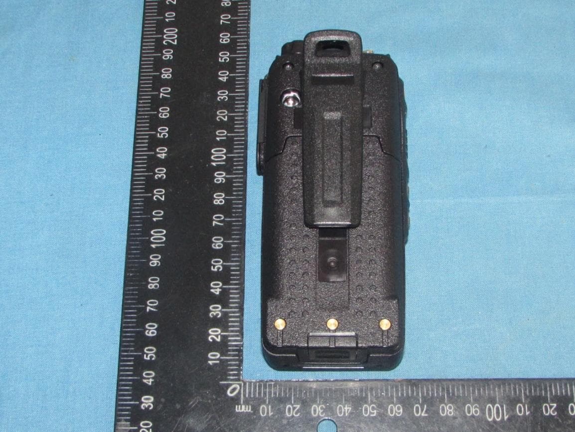
VSODX-7400
Jul 16, 2023Digital 5W Portable Radio
Equipment Class
TNF - Licensed Non-Broadcast Transmitter Held to Face
VSODX-300
Jul 16, 2023Digital 2W Portable Radio
Equipment Class
TNF - Licensed Non-Broadcast Transmitter Held to Face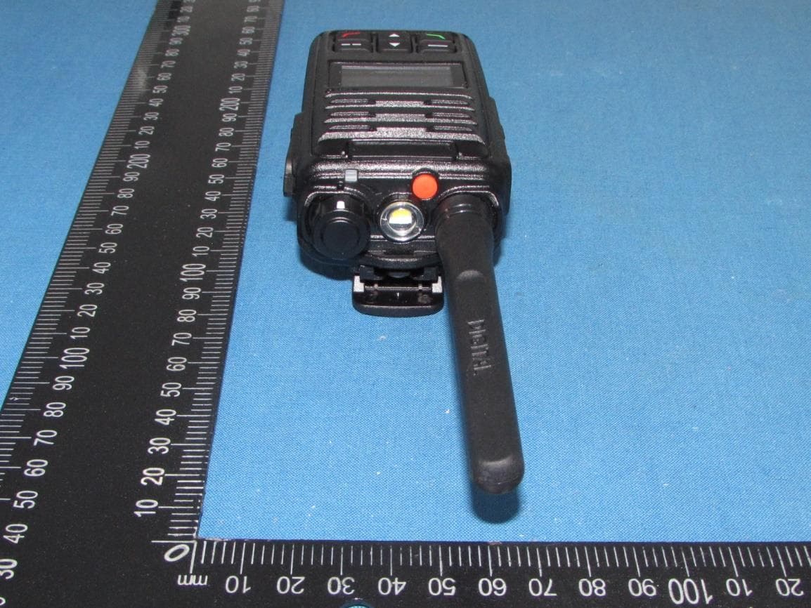
VSODX-5400
Sep 12, 2021Digital 5W Portable Radio
Equipment Class
TNF - Licensed Non-Broadcast Transmitter Held to Face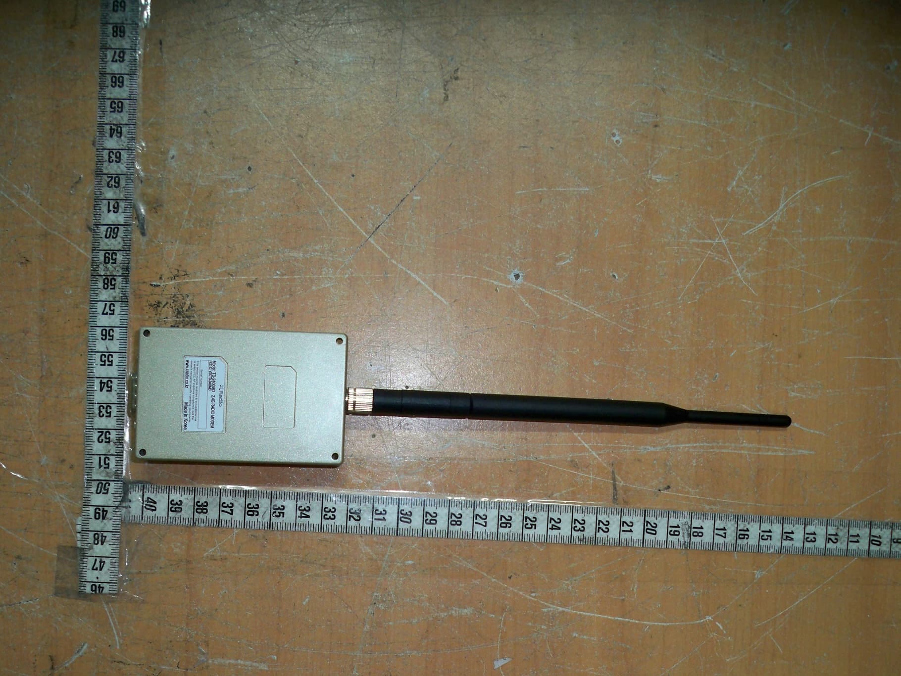
VSOTD-2400MD
Apr 29, 2013Zigbee Data Modem Module
Equipment Class
DTS - Digital Transmission System