VSOXV-100AFM TRANSCEIVER
YEONHWA M TECH CO.,LTD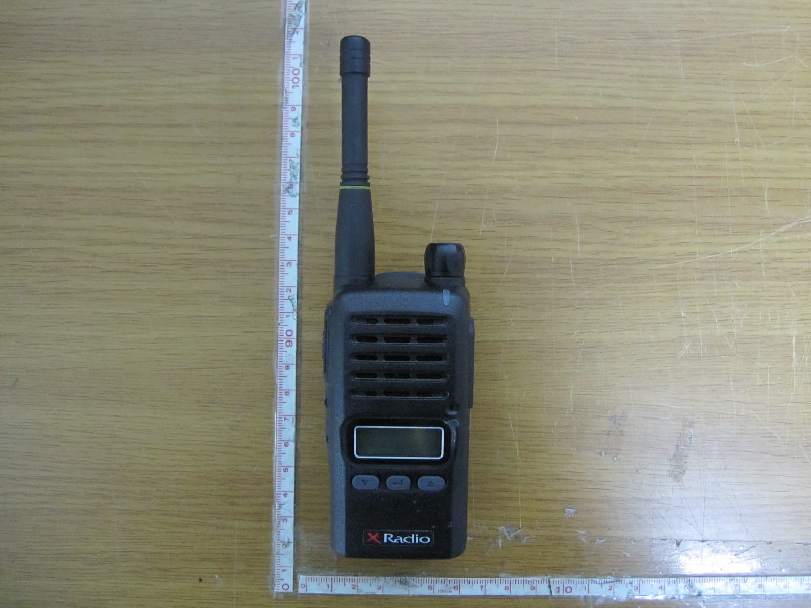
Click to zoom
Application Details
- Equipment Class
- TNF - Licensed Non-Broadcast Transmitter Held to Face
- Date of Grant
- Jan 22, 2013
- Application Purpose
- Original Equipment
- Date of Application
- Jan 22, 2013
- Equipment Note
- FM TRANSCEIVER
- Frequency Range
- 140.00000000 - 174.00000000
- Company
- YEONHWA M TECH CO.,LTD
- Country
- South Korea
Documents & Files
Document Text
Text extracted from the exhibit documents filed with the FCC. Open a document above to read the original.
Users Manual
SERVICE MANUAL VHF Transceiver XV-100A * This Service manual is subject to change according to improvement of XV-100A Portable Radio without notice. * Version #2 (2012-11-16) 2 ==== CONTENTS ==== 1. XV-100A Features ------------------------------------------------------- 3 2. Components of XV-100A Radio ------------------------------------------------------- 4 3. Appearance of XV-100A Radio ---------------------------------------------------- 5 4. Basic Operation of XV-100A ------------------------------------------------------ 7 5. Operating XV-100A RADIO ------------------------------------------------------- 8 6. Operating Instructions of XV-100A ----------------------------------------------- 10 7. Safety Notes ------------------------------------------------- 15 8. Specification ------------------------------------------------- 17 3 1. XV-100A Features The features of XV-100A are various as below. XV-100A can used under tough indu strial environments as well as public places. XV-100A series have following functions: 128 channels and 16 groups are selectable Call guard squelch of standardized CTCSS(52) / DCS(104), Invert DCS(104) Dual Tone Modulation Frequency (DTMF) Normal scanning / Priority scanning VOX(Voice Operated Transmit) BCL(Busy Channel Lock)/BCLO(Busy Channel Lock Out) Time-Out Timer (TOT) Built-in Weather Channel Channel Spacing Only 12.5KHz Selectable Squelch Level(0~4) Monitor Signal Strength Meter(RSSI) Battery Status Indicator High-Quality Audio Output PLL synthesizer method DC+3.7V 1,800mAH rechargeable Li-ion employment quantity battery use Advanced Speaker Protection technology Various Parameters and PC downloading methods PC Tuning Flash Memory Advantage 4 2. Components of XV-100A Radio * Components could be changed by buyer request. Figure 2-1) standard components of XV-100A Radio Replacement Parts TJA-1800LI Battery - 1800 mAH Lithium ion TJA-341 Antenna - VHF TJA-300L Charger - Rapid Rate TJA- 30BC Belt Clip Optional Accessories ACC-600TJ3 Vehicular Charger - Single Unit ACC-6110TJ3 Charger - 6 Unit Gang Charger TA-836X Speaker Microphone - Standard TA-850X Speaker Microphone - Heavy Duty TA-818X Ear Speaker (Discreet Audio Cord) w/Lapel Mic/PTT TA-819X Ear Speaker (“D” Hook) w/Lapel Mic/PTT 5 TJA-30NC Case - Nylon w/Belt Loop/Swivel 3. Appearance of XV-100A Radio Figure 3-1) Appearance of XV-100A 6 Figure 3-2) XV-100A LCD Indication 4. Basic Operation of XV-100A Pease read this manual carefully before using XV-100A series Radio. This manual contains important information about using Radio. 4.1 Installation and Removing the Antenna To install the antenna, insert the antenna into antenna connector and screw the antenna clockwise. To remove the antenna, screw the antenna counter clockwise. Figure 4-1) Installation and Removing the Antenna When installation of the antenna, giving a strong pressure to the Radio or pulling the antenna with a strong power from the Radio can make a damage on the antenna connector, which may cause the Radio to have a critical problem. 4.2 Installation and Removing the Battery 4.2.1 Installation of the battery To install battery, slide up the battery towards the top of the radio until battery latch is locked. 4.2.2 Removing the Battery - Slide the battery latch located on the bottom of radio to the open position as shown in Figure 4-2. - The battery is removed by pressing it against and sliding it towards the bottom of the radio 7 Figure 4-2) Installation and Removing the Battery 4.3 Installation and Removing the Belt Clip - To attach belt clip to radio, align belt clip rails with the grooves in radio and slide the belt clip onto the mounting rails until it latches into place. - To remove belt clip from radio, push up on tab of belt clip with flat bladed screwdriver and at the same time, slide the belt clip towards the top of Radio (Figure4-3). Figure 4-3) Installation and Removing the Belt Clip 4.4 Accessory connector Accessory connector is used to connect external speaker/Mic, and headset, etc. Please close the cover when nothing is connected. Figure 4-4) Accessory connector 8 5. Charging the Battery 5.1 Safety Notes 1) The radio of XV-100A series receives power from high-performance Li-ion battery (TJA-1800LI). TJA-1800LI Battery is safe of high performance and highly reliable, and could be charged very fast. TJA-1800LI Battery has been designed suitably only for the charger The charging of the enclosed Radio on the other maker’s charger will cause a damage on the battery and also, will cause a trouble on the Radio. 2) Please charge the battery before using the radio for best performance and safety. 3) When you charge the battery that is installed in the Radio, please turn off the radio first to charge the battery. The continuous rapid discharge (for example, when making a short circuit on the ‘+’ terminal of battery by a metal substance) may make a fatal defect and the battery can be exploded. Also, it can cause a fire. 4) Using the correct battery will improve the efficiency and safety. 5.2 The Time of Charging Low battery voltage will make the radio less coverage and also make the performance worse. Please charge the battery in case of following: ① When you think performance of the radio becomes lower ② When the red lamp on RX/TX Led blinks (every 0.5 second) during transmission or reception ③ When the battery icon blinks ④ When “beep” sound is generated while the radio is in use. 5.3 How to Charge 1) Plug the TJA-300L charger into the electricity power outlet. 2) When charging the Radio with the battery installed, please turn off the power of the Radio and place the Radio on the charger (The charger has a slide slot.). 3) After completion of the charging, the green LED on the charger will light. However, please continue the charging for 30 more minutes for the complete full charge. 9 status LED indication status LED indication During charging Red LED lights. Detecting error Red LED is off.…
Text truncated - open the document above for the full version.
Attestation Statements
November 16, 2012 Bay Area Compliance Laboratories Corp. 1274 Anvilwood Avenue Sunnyvale, CA 94089 In re: YEONWHA M TECH CO.,LTD FCC Application for FCC ID:VSOXV-100A Cover letter Gentlemen; 1. Power output listed is at the antenna terminal of the device. This device must transmit with a source-based time-averaging duty factor not exceeding 50%. This device must be restricted to work related operations in an Occupational/Controlled RF exposure Environment. All qualified end users of this device must receive training to have the knowledge to control their exposure conditions and/or duration to comply with Occupational/Controlled exposure limit 2. Please remove the SAR information exhibit from the application; as you can see, it is not proper for this filing 3. Please see the attached the EXT photo1 , and user manual Truly yours, Hwan-Dae Kim / Chief Engineer Yeonhwa M Tech Co., Ltd. YEONWHA M TECH CO.,LTD #141, 201 Haan-3dong, Gwangmyeong-si, Gyeonggi-do, Korea
Cover Letter(s)
YEONHWA M TECH CO.,LTD #141, 201 Haan-3dong, Gwangmyeong-si, Gyeonggi-do, Korea November 16, 2012 Federal Communications Commission Equipment Authorization Branch 7435 Oakland Mills Road Columbia, MD 21046 FCC Authorization To whom it may concern: We YEONHWA M TECH CO.,LTD , the undersigned, Hereby authorizes Bay Area Compliance Laboratory Corporation to act on its behalf in all matters relating to application for Equipment authorization, including the signing of all documents relating to these matters. All acts carried out by Bay Area Compliance Laboratory Corporation on our behalf shall have the same effect as our own action. We, the undersigned, hereby certify that we are not subject to a denial of federal benefits, that includes FCC benefits, pursuant to Section 5301 of the Anti-Drug Abuse Act of 1988, 21 U.S.C. 853(a). This authorization is valid until further written notice from the applicant. Sincerely Yours, Hwan-Dae Kim / Chief Engineer Yeonhwa M Tech Co., Ltd. Subject: Agent Authorization
Cover Letter(s)
YEONWHA M TECH CO.,LTD #141, 201 Haan-3dong, Gwangmyeong-si, Gyeonggi-do, Korea YEONWHA M TECH CO.,LTD #141, 201 Haan-3dong, Gwangmyeong-si, Gyeonggi-do, Korea November 16, 2012 Federal Communications Commission Equipment Authorization Branch 7435 Oakland Mills Road Columbia, MD 21046 In re : YEONWHA M TECH CO.,LTD FCC ID : VSOXV-100A Request for Confidentiality Pursuant to Sections 0.457 and 0.459 of the Commission’s Rules (CFR 47), and Section 552 (b) (4) of the Freedom of Information Act, YEONWHA M TECH CO.,LTD hereby requests confidentiality and treatment of certain information accompanying this application. The materials contain trade secrets and proprietary information not customarily released to the public. The public disclosure of these matters might be harmful to the Applicant and provide unjustified benefits to its competitors. We are also hereby request Short-Term Confidentiality for 180 days after the grant as outlined in Public Notice DA 04-1705. This provision will give YEONWHA M TECH CO.,LTD temporary confidentiality of commercially sensitive information prior to product release. The requested Confidential and Temporary Confidential exhibits are listed as follows: Exhibit Type File Name CONFIDENTIAL Schematics CONF APPENDIX VSOXV-100A SCH DIA.pdf Parts list CONF APPENDIX VSOXV-100A PL.pdf Block diagram CONF APPENDIX VSOXV-100A BLK DIA.pdf Operational description CONF APPENDIX VSOXV-100A OpDes.pdf SHORT-TERM CONFIDENTIAL External Photos SHORT-TERM CONF VSOXV-100A EXT Photo.pdf Internal Photos SHORT-TERM CONF VSOXV-100A INT Photo.pdf Te s t-Setup Photos SHORT-TERM CONF VSOXV-100A Test Photo.pdf User’s Manual SHORT-TERM CONF VSOXV-100A Manual.pdf The Applicant understands that pursuant to Rule 0.457, disclosure of this application and all accompanying documentations, where applicable, will not be made public before the date of the Grant for this application. Sincerely, Hwan-Dae Kim / Chief Engineer Yeonhwa M Tech Co., Ltd.
Cover Letter(s)
YEONHWA M TECH CO.,LTD #141, 201 Haan-3dong, Gwangmyeong-si, Gyeonggi-do, Korea November 16, 2012 Federal Communications Commission Equipment Authorization Branch 7435 Oakland Mills Road Columbia, MD 21046 Subject: FCC ID: VSOXV-100A justification letter for expanded frequency range 140 - 174 MHz Gentlemen; You have asked YEONHWA M TECH CO.,LTD for justification to have the 140-174 MHz freq range appear on the face of the FCC Grant of Certification for a Part 90 Certification. This frequency range is regarded as usual & customary by United States Federal Government and its various departments, user organizations and the military to appear on the face of the equipment Grant of Certification. (1) YEONHWA M TECH CO.,LTD Marketing Department plans to ensure that USA users, other than those specifically identified in this letter, not operate within bands 140-150 MHz, as controlled by the users’ FCC station license. (2) This device will not be marketed to USA users, other than those identified in the letter, namely the US Government and its various departments & military, for operation in 140-150 MHz frequency range. Sincerely, Hwan-Dae Kim / Chief Engineer Yeonhwa M Tech Co., Ltd.
External Photos
FCC ID: VSOXV-100A Copyright ○ c 2012, LTA Co., Ltd. Page 1 of 3 FCC ID: VSOXV-100A Copyright ○ c 2012, LTA Co., Ltd. Page 2 of 3 FCC ID: VSOXV-100A Copyright ○ c 2012, LTA Co., Ltd. Page 3 of 3 FCC ID: VSOXV-100A Copyright ○ c 2012, LTA Co., Ltd. Page 1 of 2 Distance between antenna and user body FCC ID: VSOXV-100A Copyright ○ c 2012, LTA Co., Ltd. Page 2 of 2 Distance between antenna and user body
ID Label/Location Info
FCC ID: VSOXV-100A Copyright Ⓒ 2012, LTA Co., Ltd. SAMPLE LABEL & LOCATION
Internal Photos
FCC ID: VSOXV-100A Copyright ○ c 2012, LTA Co., Ltd. Page 1 of 2 FCC ID: VSOXV-100A Copyright ○ c 2012, LTA Co., Ltd. Page 2 of 2
RF Exposure Info
YEONWHA M TECH CO.,LTD #141, 201 Haan-3dong, Gwangmyeong-si, Gyeonggi-do, Korea RF EXPOSURE EVALUATION FCC KDB 447498 D01 General RF Exposure Guidance v05 (October 24, 2012) Appendix A SAR Test Exclusion Thresholds for 100 MHz – 6GHz and ≤ 50 mm Approximate SAR test exclusion power thresholds at selected frequencies and test separation distances are illustrated in the following table. MHz 5 10 15 20 25 mm 150 39 77 116 155 194 SAR Test Exclusion Threshold (mW) 300 27 55 82 110 137 450 22 45 67 89 112 835 16 33 49 66 82 900 16 32 47 63 79 1500 12 24 37 49 61 1900 11 22 33 44 54 2450 10 19 29 38 48 3600 8 16 24 32 40 5200 7 13 20 26 33 5400 6 13 19 26 32 5800 6 12 19 25 31 MHz 30 35 40 45 50 mm 150 232 271 310 349 387 SAR Test Exclusion Threshold (mW) 300 164 192 290 246 274 450 134 157 179 201 224 835 98 115 131 148 164 900 95 111 126 142 158 1500 73 86 98 110 122 1900 65 76 87 98 109 2450 57 67 77 86 96 3600 47 55 63 71 79 5200 39 46 53 59 66 5400 39 45 52 58 65 5800 37 44 50 56 62 Portable PTT devices .When the occupational exposure limit applies, these power thresholds are increased by a factor of five (5) to determine the test requirements. SAR is required for PTT devices with maximum output power greater than these thresholds.. (Contunued) Results 1 – Speak mode: Manufacturer declares RF Safety Distance of 30mm (232mW // on Appendix A) 232 (mW) * 5 = 1,160 (mW) = SAR Test Exclusion Threshold In General Duty cycle of PTT device is 50%, 1,945 (mW) * 0.5 = 972.5 (mW) < 1,160 (mW) Results 2 - Body Worn: Manufacturer declares RF Safety Distance of 30mm (232mW // on Appendix A) 232 (mW) * 5 = 1,160 (mW) = SAR Test Exclusion Threshold In General Duty cycle of PTT device is 50%, 1,945 (mW) * 0.5 = 972.5 (mW) < 1,160 (mW) Please refer to Users Manual for details of RF Exposure Information and Label Information. (Continued) Speak Mode Body-Worn 3cm Antenna Center Antenna Center
Test Report
Ref. No.: LR500111211C Copyright ○ c 2012, LTA Co., Ltd. Page 1 of 30 243 Jubug-Ri,Yangji-Myeon, Yongin-Si, Gyeonggi-Do, Korea 449-822 Tel: +82-31-323-6008 Fax: +82-31-323-6010 http://www.ltalab.com CERTIFICATION OF COMPLIANCE FCC ID APPLICANT Device Category : VHF FM Transceiver Manufacturing Description : FM TRANSCEIVER Manufacturer : YEONHWA M TECH CO.,LTD Trade mark : XRadio Model name : XV-100A Varient Model name Serial number : : XV-100P Identical prototype FCC Rule Part(s) : §2, §90 Frequency Range : 140 ~ 174MHz RF Output Power : 2W Channel Separation : 12.5kHz Emission Designators: : 10K4F3E Data of issue : November 16, 2012 This test report is issued under the authority of: The test was supervised by: Kyu-Hyun Lee, Manager Jung-Moo Her, Test Engineer This test result only responds to the tested sample. It is not allowed to copy this report even partly without the allowance of the test laboratory. The report must not be used by the client to claim product certification, approval, or endorsement by NVLAP, NIST, or any agency of the Federal Government. NVLAP LAB Code.: 200723-0 Dates of Tests: November 05~16, 2012 Test Report S/N: LR500111211C Test Site : LTA CO., LTD. VSOXV-100A YEONHWA M TECH CO.,LTD Ref. No.: LR500111211C Copyright ○ c 2012, LTA Co., Ltd. Page 2 of 30 TABLE OF CONTENTS 1. GENERAL INFORMATION’S -------------------------------------------------------------------------- 2. INFORMATION’S ABOUT TEST ITEM ------------------------------------------------------------- 3. TEST REPORT --------------------------------------------------------------------------------------------- 3.1 SUMMARY OF TESTS ------------------------------------------------------------------------------- 3.2 REQUIREMENTS ------------------------------------------------------------------------------------- 3.2.1 CARRIER OUTPUT POWER (CONDUCTED) -------------------------------------------- 3.2.2 UNWANTED EMISSIONS (TRANSMITTER CONDUCTED) (CONDUCTED) ---- 3.2.3 FIELD STRENGTH OF SPURIOUS RADIATION ---------------------------------------- 3.2.4 EMISSION MASKS (OCCUPIED BANDWIDTH) ---------------------------------------- 3.2.5 TRANSIENT FREQUENCY BEHAVIOR --------------------------------------------------- 3.2.6 AUDIO LOW PASS FILTER (VOICE INPUT) ------------------------------------------------- 3.2.7 AUDIO FREQUENCY RESPONSE ----------------------------------------------------------- 3.2.8 MODULATION LIMITING --------------------------------------------------------------------- 3.2.9 FREQUENCY STABILITY (TEMPERATURE VARIATION) ----------------------------- 3.2.10 NECESSARY BANDWIDTH AND EMISSION BANDWIDTH ------------------------ APPENDIX APPENDIX I TEST EQUIPMENT USED FOR TESTS --------------------------------------------- APPENDIX II TEST PLOTS ----------------------------------------------------------------------------- 3 4 5 5 6 6 7 10 12 13 14 15 16 17 18 19 21 Ref. No.: LR500111211C Copyright ○ c 2012, LTA Co., Ltd. Page 3 of 30 1. General information’s 1- 1 Test Performed Company name : LTA Co., Ltd. Address : 243, Jubug-ri,Yangji-Myeon,Youngin-Si, Kyunggi-Do, Korea. 449-822 Web site : http://www.ltalab.com E-mail : [email protected] Telephone : +82-31-323-6008 Facsimile : +82-31-323-6010 Quality control in the testing laboratory is implemented as per ISO/IEC 17025 which is the “General requirements for the competents of calibration and testing laboratory”. 1- 2 Accredited agencies LTA Co., Ltd. is approved to perform EMC testing by the following agencies: Agency Country Accreditation No. Validity Reference NVLAP U.S.A 200723-0 2013-09-30 ECT accredited Lab. RRL KOREA KR0049 2013-04-24 EMC accredited Lab. FCC U.S.A 610755 2014-04-27 FCC filing FCC U.S.A 649054 2013-04-13 FCC CAB VCCI JAPAN R2133(10m), C2307 2014-06-21 VCCI registration VCCI JAPAN T-2009 2013-12-23 VCCI registration VCCI J APA N G-563 2015-05-28 VCCI registration IC CANADA 5799A-1 2015-06-21 IC filing Ref. No.: LR500111211C Copyright ○ c 2012, LTA Co., Ltd. Page 4 of 30 2. Information’s about test item 2- 1 Client & Manufacturer Company name : YEONHWA M TECH CO.,LTD Address : #141, 201 Haan-3dong, Gwangmyeong-si, Gyeonggi-do, Korea TEL / FAX : +82-2-3281-7270 / +82-2-3281-7271 2- 2 Equipment Under Test (EUT) Trade name : VHF FM Transceiver FCC ID : VSOXV-100A Model name : XV-100A Varient Model name Serial number : : XV-100P Identical prototype Date of receipt : November 5, 2012 EUT condition : Pre-production, not damaged Frequency Range : 140 ~ 174 MHz RF output power : 2W Channel Separation : 12.5kHz Duty cycle TX power : 5(Tx) : 5(Rx) : 90(Stand-by) Speaker Impedance : 16 ohm Audio Output Power : 1.0Watt across an 16-ohm load Power Source : DC 3.7V by battery (Li-ion) Firmware version : V2.0 2- 3 Tested frequency LOW MID HIGH Frequency (MHz) 140.0125 155.0000 173.9875 2- 4 Ancillary Equipment Equipment Model No. Serial No. Manufacturer - - - - Ref. No.: LR500111211C Copyright ○ c 2012, LTA Co., Ltd. Page 5 of 30 3. Test Report 3.1 Summary of tests FCC Part Section(s) Parameter Status (note 1) 2.1046 (a) / 90.205 Carrier Output Power (Conducted) C 2.1051 / 90.210 Unwanted Emissions (Transmitter Conducted) C 2.1053 (a) / 90.210 Field Strength of Spurious Radiation C 2.1049 (c) (1) / 90.210 Emission Masks (Occupied Bandwidth) C 90.214 Transient Frequency Behavior C 2.1047 (a) / 90.207 Audio Low-Pass Fliter Response C 2.1047 (a) / 90.207 Audio Frequency Response C 2.1047 (b) / 90.207 Modulation Limiting C 2.1055 (a) (1) / 90.213 Frequency Stability (Temperature Variation) C 2.1055 (b) (1) / 90.213 Frequency Stability (Voltage Variation) C 2.202 (g) Necessary Bandwidth and Emission Bandwidth C Note 1: C=Complies NC=Not Complies NT=Not Tested NA=Not Applicable Note 2: The data in this test report are traceable to the national or international standards. The sample was tested according to the following specification: *FCC Rules and Regulations, Volume II; Part 2, Sub-part J, Sections 2.947, 2.1033(c), 2.1046, 2.1047, 2.1079, 2.1051, 2.…
Text truncated - open the document above for the full version.
Test Setup Photos
FCC ID: VSOXV-100A Copyright Ⓒ 2012, LTA Co., Ltd. Page 1 of 1 Radiated Emission
Contact Information
Applicant
HWAN-DAE KIM
Test Firm
LTA Co.,LtdAhn Chulho
Technical Specifications
| # | Rule Parts | Frequency Range | Power Output | Emission | Tolerance |
|---|---|---|---|---|---|
| 1 | 90 | 140 MHz - 174 MHz | 1.945 W | 10K4F3E | 0.2500000000 ppm |
Other Applications from YEONHWA M TECH CO.,LTD
VSODX-7100
Jul 16, 2023Digital 5W Portable Radio
Equipment Class
TNF - Licensed Non-Broadcast Transmitter Held to Face
VSODX-7400
Jul 16, 2023Digital 5W Portable Radio
Equipment Class
TNF - Licensed Non-Broadcast Transmitter Held to Face
VSODX-300
Jul 16, 2023Digital 2W Portable Radio
Equipment Class
TNF - Licensed Non-Broadcast Transmitter Held to Face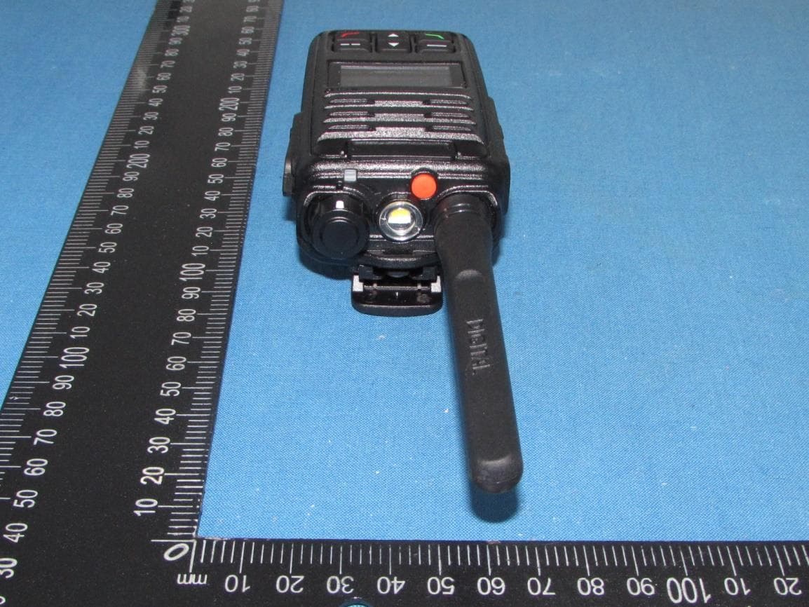
VSODX-5400
Sep 12, 2021Digital 5W Portable Radio
Equipment Class
TNF - Licensed Non-Broadcast Transmitter Held to Face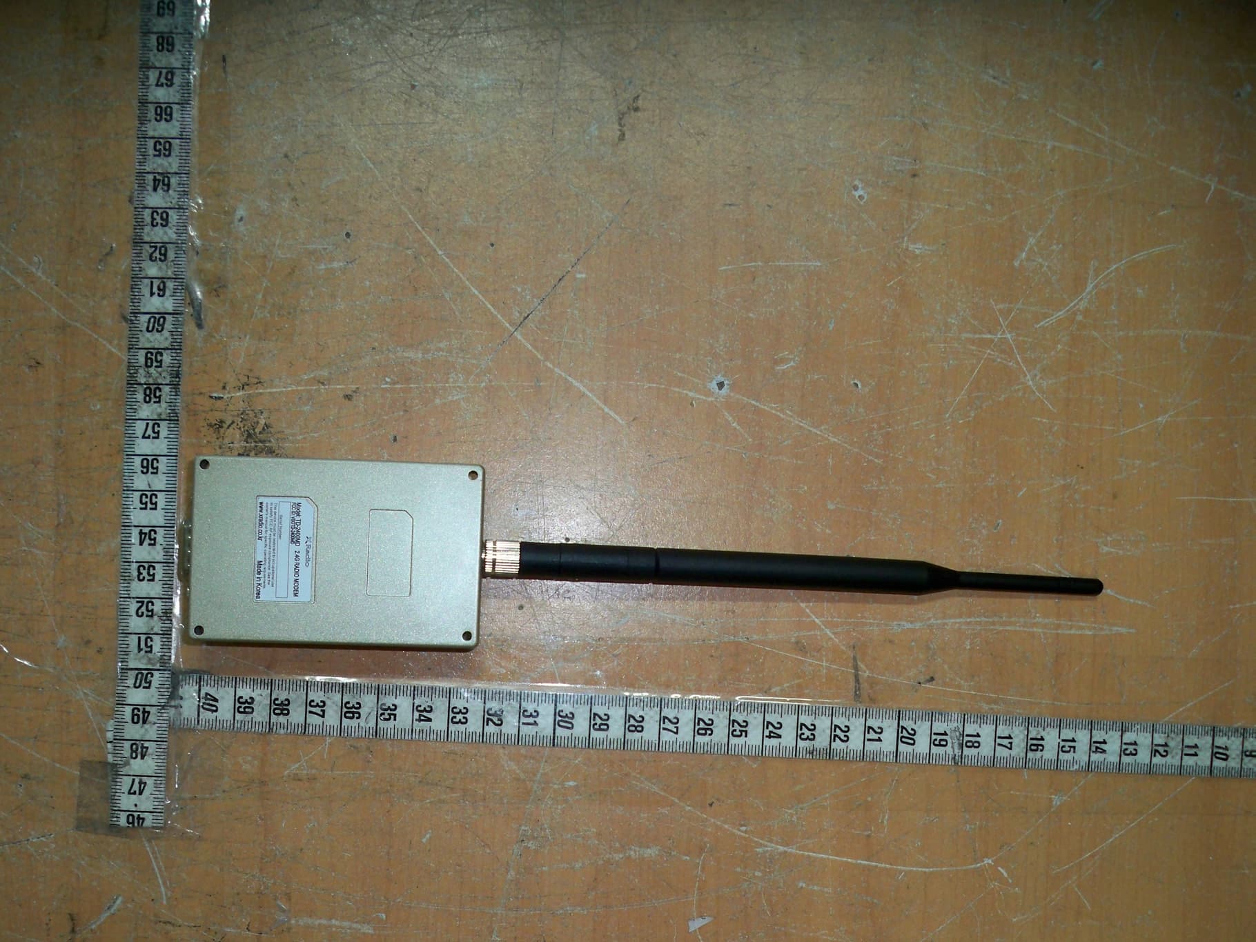
VSOTD-2400MD
Apr 29, 2013Zigbee Data Modem Module
Equipment Class
DTS - Digital Transmission System