VUI-CMST173IEEE 802.11b/g/n Wireless LAN Module (Single Antenna)
PEGATRON CORPORATION
Click to zoom
Application Details
- Equipment Class
- DTS - Digital Transmission System
- Date of Grant
- Jun 03, 2014
- Application Purpose
- Original Equipment
- Date of Application
- Jun 02, 2014
- Equipment Note
- IEEE 802.11b/g/n Wireless LAN Module (Single Antenna)
- Frequency Range
- 2412.00000000 - 2462.00000000
- Company
- PEGATRON CORPORATION
- Country
- Taiwan
Documents & Files
Document Text
Text extracted from the exhibit documents filed with the FCC. Open a document above to read the original.
Users Manual
AW-NU173 IEEE 802.11 b/g/n WLAN Wireless Module User’s Manual I. Introduction i. Overview AzureWave Technologies, Inc. introduces the first IEEE 802.11b/g/n WLAN module Card -AW-NU173. By using AW-NU173, the customers can easily enable the Wi-Fi embedded applications with the benefits of high design flexibility, short development cycle, and quick time-to-market. Compliance with the IEEE 802.11b/g/n standard, the AW-NU173 uses Direct Sequence Spread Spectrum (DSSS), Orthogonal Frequency Division Multiplexing (OFDM), DBPSK, DQPSK, CCK and QAM baseband modulation technologies. A high level of integration and full implementation of the power management functions specified in the IEEE 802.11 standard minimize the system power requirements by using AW-NU173. In addition to the support of WPA/WPA2 and WEP 64-bit and 128-bit encryption, the AW-NU173 also supports the IEEE 802.11i security standard through the implementation of Advanced Encryption Standard (AES)/Counter Mode CBC-MAC Protocol (CCMP), Wired Equivalent Privacy (WEP) with Temporal Key Integrity Protocol (TKIP), Advanced Encryption Standard (AES)/Cipher-Based Message Authentication Code (CMAC), and WLAN Authentication and Privacy Infrastructure (WAPI) security mechanisms. For the video, voice and multimedia applications the AW-NU173 support 802.11e Quality of Service (QoS). The AW-NU173 supports USB for WLAN to the host processor. ii. Features USB interfaces support for WLAN Multiple power saving modes for low power consumption IEEE 802.11i for advanced security Quality of Service (QoS) support for multimedia applications iii. Product Review 1. Connection Mode ◎Infrastructure Mode Infrastructure mode needs an access point to establish the network, which can provide wireless accesses within valid range for users to communicate with others or transmit data with a wired network. There are several benefits of Infrastructure networking: √ Roaming: a wireless LAN enabled computer can physically move from the operating range of one access point to the other without losing connection. There is a quick association made between new access point and wireless device as the computer traverses from the coverage of one access point to another. √ Range Extension: each wireless LAN enabled computer within the range of access point can communicate with other wireless LAN enabled computers within the effective range from the access point. √ Wired to wireless LAN connection: the access point will establish a bridge between wireless LAN and other wired counterparts. Infrastructure Mode ◎Ad-hoc Mode The difference between Ad-hoc mode and Infrastructure mode is that Ad-hoc mode does not need the access point or router. When you use this mode, your computer will act as a server within the valid range and connect directly to others in the same LAN workgroup. Ad-hoc Mode It is recommended to choose this mode when there is no access point showed on your wireless network. 1. Initial Command i. RF Tx/Rx Performance Test As the information showed on your screen, please enter these commands below to start your test. (Figure 3) Command: 1 Wi-Fi testing Figure 3 Generate 802.11a/b/g/n Packet commands a. Tx on CH 1 at 17 dBm with a CCK-11Mbps data rate in 20 MHz BW mode on path A 10 1 1 // Set Path A Only 112 0 // Set to 20 MHz BW 22 1 17 0 // Set to CH 1 at 17dBm Output Power with CCK/BPSK Data Rate on Path A 25 1 4 // Tx at 11 Mbps 25 0 // Stop Tx ------------------------------------------------------------------------------------------------------------------------------ b. Tx on CH 1 at 17 dBm with a CCK-11Mbps data rate in 20 MHz BW mode on path B 10 0 0 // Set Path B Only 112 0 // Set to 20 MHz BW 22 1 17 0 // Set to CH 1 at 17dBm Output Power with CCK/BPSK Data Rate on Path B 25 1 4 // Tx at 11 Mbps 25 0 // Stop Tx ------------------------------------------------------------------------------------------------------------------------------ c. Tx on CH 6 at 12 dBm with a MCS7 Data rate in 40 MHz BW Mode on Path A 10 1 1 // Set Path A 112 1 // Set to 40 MHz BW 22 6 12 1 // Set to CH6 at 12dBm Output Power with OFDM Data Rate on path A 25 1 22 // Tx at MCS 7 25 0 // Stop Tx ------------------------------------------------------------------------------------------------------------------------------ Data rate set up B mode & G mode: 1Mbps 5.5Mbps 11Mbps 6Mbps 9Mbps 12Mbps 18Mbps 24Mbps 1 3 4 6 7 8 9 10 36Mbps 48Mbps 54Mbps 11 12 13 N mode: MCS0 MCS1 MCS2 MCS3 MCS4 MCS5 MCS6 MCS7 15 16 17 18 19 20 21 22 After you type above command, you can measure the 802.11b/g/n packet by your RF test instrument (exp: Agilent 4010, IQview...). Generate 802.11b/g/n continuous symbol Commands a. Cont. Tx on CH 7 at 12 dBm with a MCS7 Data rate in 20 MHz BW Mode on Path A 10 1 1 // Set Path A 112 0 // Set to 20 MHz BW 22 7 12 1 // Set to CH7 at 12 dBm Output Power with OFDM Data Rate on Path A 17 1 22 // Cont. Tx at MCS7 17 0 // Stop Cont. Tx 1.5 Test RX sensitivity Commands a. Rx on CH 7 in 20 MHz BW Mode on both Path A 25 // Stop Tx 10 1 1 // Set to Path A 112 0 // Set to 20 MHz BW 12 7 // Set to CH 100 31 // Clear all the received packets 32 // Get Rx Packet Count and then clear the Rx packet counter 1.6 Others Commands (1) Command 45 (2) Command 99 Federal Communication Commission Interference Statement This device complies with Part 15 of the FCC Rules. Operation is subject to the following two conditions: (1) This device may not cause harmful interference, and (2) this device must accept any interference received, including interference that may cause undesired operation. This equipment has been tested and found to comply with the limits for a Class B digital device, pursuant to Part 15 of the FCC Rules. These limits are designed to provide reasonable protection against harmful interference in a residential installation. This equipment generates, uses and can radiate radio frequency energy and, if not installed and used in accordance with the instructions, may cause har…
Text truncated - open the document above for the full version.
Cover Letter(s)
規 格 承 認 書 Approval Sheet 客 戶 名 稱 Customer Name: 永碩 產 品 名 稱 Product description: Single Band antenna-2 產 品 型 號 Model Name: Canon 泓 淋 料 號 Hong Lin P/N: 290-30068 客戶料號 Customer P/N: 版 別 日 期 Version: X5 Date: 2013/12/25 客戶承認簽印 CUSTOMER APPROVED BY 供應商承認簽印 VENDER APPROVED BY Checked By: Checked By: Approval By: Approval By: 工廠/Factory: 1) 深圳市寶安區松崗鎮沙浦圍村第二工業區六棟; 電話+86-755-27090678; 電子信箱: [email protected] Building 6.No.2 Industrial Park, Shapuwei, Songgang Town, Baoan District,Shenzhen, Guangdong, China; Tel:+86-755-27090678 ; E-mail:[email protected] 2) 江蘇省常熟市高新技術產業園柳州路8號; 電話: +86-512-51538298; 電子信箱: [email protected] No.8 Liuzhou Road, Yushan Industrial Park, Hi-tech Development Zone, Changshu, Jiangsu, China Tel:+86-512-51538298; E-mail:[email protected] Content Item Page 1. Specification (規格表)..................................................................... 1 2. Antenna Picture................................................................................ 2 3. Test data (測試資料)........................................................................ 3 3.1 Return loss................................................................................ 3 3.2 Radiation Pattern..................................................................... 4 3.3 Gain Table................................................................................. 5 4. Antenna assembly (成品圖)............................................................ 6 1 1 Specification 1.1 Electrical Properties(With Housing) 1.1.1 Frequency Range---------------------- 2.4GHz~2.5GHz 1.1.2 Impedance------------------------------ 50Ω 1.1.3 VSWR------------------------------------- 1.92:1 1.1.4 Return Loss----------------------------- -10dB or Less 1.1.5 Peak Gain-------------------------------- 2.82 dBi 1.1.6 Admitted Power------------------------ 1W 1.1.7 Cable-------------------------------------- Ø1.13 1.1.8 Antenna Type-------------------------- PCB Type 1.2 Physical Properties 1.2.1 Antenna Body----------------------- FR4 1.2.2 Operating Temp-------------------- -10°C~+60°C 1.2.3 Storage Temp----------------------- -10°C~+70°C 2 2 Antenna Picture 3 3 Test data 3.1 Return Loss and VSWR 2.4 G 4 3.2 Radiation Pattern 2.4 G 3.3 Gain Table 5 4 Antenna Assembly (成品圖)
Cover Letter(s)
FCC, Request for non-disclosure Date: 16-Jul-10 RF_501, Issue 6 Page 1 of 1 Company Name: Pegatron Corporation Address : 5F, No. 76, Ligong St., Beitou Taipei 112, Taiwan City: Taipei City Country: Taiwan To: Telefication B.V., Dept. FCC TCB Edisonstraat 12A 6902 PK ZEVENAAR The Netherlands Subject: Request for confidentiality FCC ID: VUI-CMST173 Reference number: ###### Dear FCC TCB, 1. Long-Term Confidentiality Pursuant to 47 CFR Section 0.459(a) & (b), we hereby requests non-disclosure and confidential treatment of the following materials submitted in support of FCC certification application: Bill(s) of Material Block Diagrams Operational Description Schematic Diagrams Tune-up Procedure Above materials contain secrets, proprietary and technical information, which would customarily be guarded from competitors under 47 CFR, section 0.457(d)(2). Disclosure or publication or any portion of this company confidential material to other parties could cause substantial competitive harm and provide unjustified benefits for competitors. 2. Short-Term Confidentiality (STC) Pursuant to Public Notice DA 04-1705 of the Commission’s policy, in order to comply with the marketing regulations in 47 CFR §2.803 and the importation rules in 47 CFR §2.1204, a pplicant hereby requests Short-Term Confidential treatment of the following materials (note 1): Internal Photos User’s Manual Test Set-up Photos External Photos Justification: Planned Release Date STC: (notes 2, 3, 4, 5) Date: May 19, 2014 Name and signature of applicant: Lawrence Yu Notes: 1) A document or type of document can only have ONE type of confidentiality! 2) Short-Term confidentiality is in principle for 45 days from date of grant; it can be extended max 3 times (total time 180 days max.)! 3) FCC must be informed when marketing begins earlier. 4) Release takes place automatically thus extension must be requested in time. Telefication does not remind you of this! 5) Request for extension or for release must be received by Telefication at least 7 days before date of actual marketing or before expiration of the STC period
External Photos
All View of EUT Front View of EUT Back View of EUT
ID Label/Location Info
20mm 10mm 201-140031 R M/N: AW-NU173 IEEE 802.11 b/g/n Wireless LAN Module (Single Antenna) FCC ID: VUI-CMST173 IC: 7582A-CMST173
Internal Photos
Open View of EUT – 1 Open View of EUT – 2 Open View of EUT – 3 Antenna Antenna Location
RF Exposure Info
1 MAXIMUM PERMISSIBLE EXPOSURE (MPE) 1.1 STANDARD APPLICABLE According to §1.1307(b)(1), systems operating under the provisions of this section shall be operated in a manner that ensure that the public is not exposed to radio frequency energy level in excess of the Commission’s guideline. This is a Mobile device, the MPE is required. According to §1.1310 and §2.1091 RF exposure is calculated. Limits for Maximum Permissive Exposure (MPE) Frequency Range (MHz) Electric Field Strength (V/m) Magnetic Field Strength (A/m) Power Density (mW/cm 2 ) Averaging Time (minute) Limits for General Population/Uncontrolled Exposure 0.3-1.34 614 1.63 *(100) 30 1.34-30 824/f 2.19/f *(180/f 2 ) 30 30-300 27.5 0.073 0.2 30 300-1500 / / F/1500 30 1500-15000 / / 1.0 30 F = frequency in MHz * = Plane-wave equipment power density 1.2 MAXIMUM PERMISSIBLE EXPOSURE (MPE) EVALUATION: 802.11b Frequency (MHz) Average Power Output (dBm) Output Power (W) 2412.00 16.62 0.04592 2437.00 16.90 0.04898 2462.00 16.96 0.04966 MPE Prediction Prediction of MPE limit at a given distance Equation from page 18 of OET Bulletin 65, Edition 97-01 S=PG/4πR 2 Where: S = Power density P = Power input to antenna G = Power gain of the antenna in the direction of interest relative to an isotropic radiator R = Distance to the center of radiation of the antenna Maximum avg ou tput p ower at antenn a input ter min al: 16.96 (dBm) Maximum avg ou tput p ower at antenn a input ter min al: 49.65 92 3215 (mW) Duty cycle: 100 (%) Maximum Pav : 49.65 92 3215 (mW) Antenn a gain ( typical): 2.52 (dBi) Max imu m antenn a gain: 1.786 48 7575 (numeric) Prediction distance: 20 (cm) Pred ictio n f requ ency: 2462 (MHz) MPE limit f or u ncon tr olled exposure at pr ediction 1 (mW /c m 2) Power density at predication frequency at 20 (cm) 0.017658 (mW/cm^2) Measurement Result The predicted power density level at 20 cm is 0.017658 mW/cm2. This is below the uncontrolled exposure limit of 1 mW/cm2 at 2462MHz.
Test Report
Report No.: ER/2014/20026 FCC ID: VUI-CMST173 Issue Date: Mar. 12, 2014 IC: 7582A-CMST173 Page: 1 of 108 Unless otherwise stated the results shown in this test report refer only to the sample(s) tested and such sample(s) are retained for 90 days only. 除非另有說明,此報告結果僅對測試之樣品負責,同時此樣品僅保留90天。本報告未經本公司書面許可,不可部份複製。 This document is issued by the Company subject to its General Conditions of Service printed overleaf, available on request or accessible at www.sgs.com/terms_and_conditions.htm and, for elec- tronic format documents, subject to Terms and Conditions for Electronic Documents at www.sgs.com/terms_e-document.htm . Attention is drawn to the limitation of liability, indemnification and jurisdiction issues defined therein. Any holder of this document is advised that information contained hereon reflects the Company’s findings at the time of its intervention only and within the limits of Client’s instructions, if any. The Company’s sole responsibility is to its Client and this document does not exonerate parties to a transaction from exercising all their rights and obligations under the transaction documents. This document cannot be reproduced except in full, without prior written approval of the Company. Any unauthorized alteration, forgery or falsification of the content or ap- pearance of this document is unlawful and offenders may be prosecuted to the fullest extent of the law. SGS Taiwan Ltd. No.134,WuKungRoad,NewTaipeiIndustrialPark,WukuDistrict,NewTaipeiCity,Taiwan24803/新北市五股區新北產業園區五工路134號 台灣檢驗科技股份有限公司 t (886-2) 2299-3279 f (886-2) 2298-0488 www.tw.sgs.com Member of SGS Group ELECTROMAGNETIC EMISSIONS COMPLIANCE REPORT INTENTIONAL RADIATOR CERTIFICATION TO FCC PART 15 SUBPART C REQUIREMENT AND INDUSTRY CANADA RSS 210 OF Product Name: IEEE 802.11 b/g/n Wireless LAN Module (Sin gle Antenna) Brand Name: AzureWave Model No.: AW-NU173 Model Difference: N/A FCC ID: VUI-CMST173 IC: 7582A-CMST173 Report No.: ER/2014/20026 Issue Date: Mar. 12, 2014 FCC Rule Part: §15.247, Cat: DTS IC Rule Part: RSS-210 issue 8 :2010, Annex 8 Prepared for: Pegatron Corporation 5F, No. 76, Ligong St., Beitou Taipei 112, Taiwan Prepared by: SGS Taiwan Ltd. Electronics & Communication Laboratory No.134, Wu Kung Road, New Taipei Industrial Park, Wuku District, New Taipei City, Taiwan 24803 Note: This report shall not be reproduced except in full, without the written approval of SGS Taiwan Ltd. This doc- ument may be altered or revised by SGS Taiwan Ltd. per- sonnel only, and shall be noted in the revision section of the document. Report No.: ER/2014/20026 FCC ID: VUI-CMST173 Issue Date: Mar. 12, 2014 IC: 7582A-CMST173 Page: 2 of 108 Unless otherwise stated the results shown in this test report refer only to the sample(s) tested and such sample(s) are retained for 90 days only. 除非另有說明,此報告結果僅對測試之樣品負責,同時此樣品僅保留90天。本報告未經本公司書面許可,不可部份複製。 This document is issued by the Company subject to its General Conditions of Service printed overleaf, available on request or accessible at www.sgs.com/terms_and_conditions.htm and, for elec- tronic format documents, subject to Terms and Conditions for Electronic Documents at www.sgs.com/terms_e-document.htm . Attention is drawn to the limitation of liability, indemnification and jurisdiction issues defined therein. Any holder of this document is advised that information contained hereon reflects the Company’s findings at the time of its intervention only and within the limits of Client’s instructions, if any. The Company’s sole responsibility is to its Client and this document does not exonerate parties to a transaction from exercising all their rights and obligations under the transaction documents. This document cannot be reproduced except in full, without prior written approval of the Company. Any unauthorized alteration, forgery or falsification of the content or ap- pearance of this document is unlawful and offenders may be prosecuted to the fullest extent of the law. SGS Taiwan Ltd. No.134,WuKungRoad,NewTaipeiIndustrialPark,WukuDistrict,NewTaipeiCity,Taiwan24803/新北市五股區新北產業園區五工路134號 台灣檢驗科技股份有限公司 t (886-2) 2299-3279 f (886-2) 2298-0488 www.tw.sgs.com Member of SGS Group VERIFICATION OF COMPLIANCE Applicant: Pegatron Corporation 5F, No. 76, Ligong St., Beitou Taipei 112, Taiwan Product Name: IEEE 802.11 b/g/n Wireless LAN Module (Single Antenna) Brand Name: AzureWave Model No.: AW-NU173 Model Difference: N/A FCC ID: VUI-CMST173 IC: 7582A-CMST173 File Number: ER/2014/20026 Date of test: Feb. 26, 2014 ~ Mar. 12, 2014 Date of EUT Received: Feb. 26, 2014 We hereby certify that: The above equipment was tested by SGS Taiwan Ltd. Electronics & Communication Laboratory The test data, data evaluation, test procedures, and equipment configurations shown in this report were made in accordance with the procedures given in ANSI C63.4:2009 and RSS-Gen. issue 3 the energy emitted by the sample EUT tested as described in this report is in compliance with conducted and radiated emission limits of FCC Rules Part 15.247 and IC RSS 210 issue 8: 2010 Annex 8. The test results of this report relate only to the tested sample identified in this report. Test By: Date Mar. 12, 2014 Marcus Tseng / Engineer Prepared By: Date Mar. 12, 2014 Julia Chang / Clerk Approved By: Date Mar. 12, 2014 Jim Chang / Supervisor Report No.: ER/2014/20026 FCC ID: VUI-CMST173 Issue Date: Mar. 12, 2014 IC: 7582A-CMST173 Page: 3 of 108 Unless otherwise stated the results shown in this test report refer only to the sample(s) tested and such sample(s) are retained for 90 days only. 除非另有說明,此報告結果僅對測試之樣品負責,同時此樣品僅保留90天。本報告未經本公司書面許可,不可部份複製。 This document is issued by the Company subject to its General Conditions of Service printed overleaf, available on request or accessible at www.sgs.com/terms_and_conditions.htm and, for elec- tronic format documents, subject to Terms and Conditions for Electronic Documents at www.sgs.com/terms_e-document.htm . Attention is drawn to the limitation of liability, indemnification and jurisdiction issues define…
Text truncated - open the document above for the full version.
Test Setup Photos
Radiated Emission Set up Photos Conducted Emission Set up Photo Conducted Setup Photo (Measurement at Antenna Port)
Contact Information
Applicant
Nancy Yu(Senior Manager)
Technical Contact
SGS Taiwan Ltd.Wills Chen
886222993279
Taiwan
Non-Technical Contact
SGS Taiwan Ltd.Wills Chen
886222993279
Test Firm
SGS Taiwan Ltd.Jason Lin
Technical Specifications
| # | Rule Parts | Frequency Range | Power Output |
|---|---|---|---|
| 1 | 15C | 2.41 GHz - 2.46 GHz | 140.00 mW |
Other Applications from PEGATRON CORPORATION
VUI-TS7A01
Nov 19, 2025Hardware wallet
Equipment Class
DXX - Part 15 Low Power Communication Device TransmitterVUI-M2U350
Sep 09, 20245G FR2 ODU
Equipment Class
DTS - Digital Transmission SystemVUIPR1400-48I
Apr 14, 20245G NR O-RU N48
Equipment Class
CBD - Citizens Band Category A and B Devices
VUI-CFWM
Dec 10, 2022Customer Facing Wi-Fi Module (CFWM)
Equipment Class
NII - Unlicensed National Information Infrastructure TX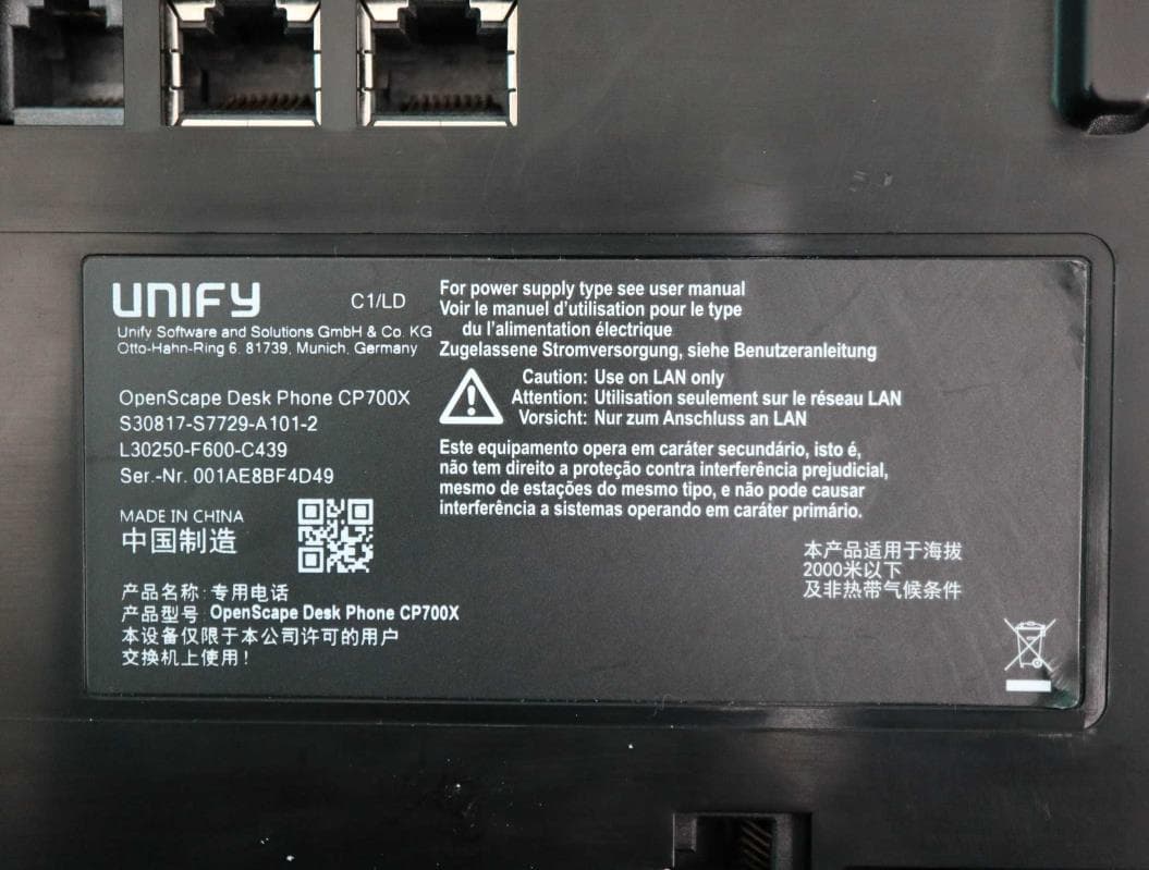
VUI-DPCP700X
May 26, 2020IP Desktop Phone
Equipment Class
DTS - Digital Transmission System