VUICLG8202-NAWireless Home Automation and Security
PEGATRON CORPORATION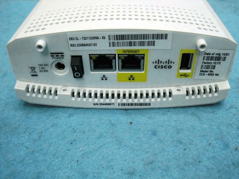
Click to zoom
Application Details
- Equipment Class
- DTS - Digital Transmission System
- Date of Grant
- Sep 21, 2014
- Application Purpose
- Original Equipment
- Date of Application
- Sep 18, 2014
- Equipment Note
- Wireless Home Automation and Security
- Frequency Range
- 2405.00000000 - 2480.00000000
- Company
- PEGATRON CORPORATION
- Country
- Taiwan
Documents & Files
Document Text
Text extracted from the exhibit documents filed with the FCC. Open a document above to read the original.
Users Manual
LEDs 1 Power Green indicates that 15V power is present and the gateway is powered on Off indicates that there is no power to the gateway 2 Cloud connectivity Green indicates connectivity is established with the backend status (S/W controlled) Off indicates connectivity to the backend 3 Controller status Green indicates that the gateway is active and in Normal mode Yellow indicates that the Linux OS has booted Red indicates that uBoot is complete Blinking green indicates that the gateway is in Test mode Blinking and other color combinations under S/W control. Can be used and assigned by application developers. Off during initial power up or when rebooting 4 ZigBee Primary Green indicates that the ZigBee controller is active RF interface active Blinking green indicates that the ZigBee controller is in Pairing mode (S/W controlled) Off indicates that the ZigBee controller is inactive 5 Z-Wave Secondary Green indicates that the Z-Wave controller is active RF interface active Blinking green indicates that the Z-Wave controller is in Inclusion mode (S/W controlled) Off indicates that the Z-Wave controller is inactive Cisco Connected Life Gateway Model CLG-8202-WW Installation Guide Welcome The Cisco Connected Life Gateway Model CLG-8202-WW is a key component of the Cisco Smart and Connected Home proposition. This service delivery platform communicates with other network devices to provide home security, home automation, and energy management solutions as well as life and health monitoring and support services. Contact your service or applications provider for more information about Cisco Connected Life products. POWER MAC: 2CABA452C858 SKU: CL-72211230NA-K9 Factory ID: F2 Model No: CLG-8202 NA Date of mfg: 14/06 INTERNET S/N: 254457522 15V DC 1.5A 22.5W 124 T16511 3 Bottom Panel 1 Power Connects to the included power adapter in the Connected Life Gateway kit 2 Power switch Switches power on and off 3 Ethernet ports Connects to an RJ-45 Ethernet port on a PC or router 4 USB 2.0 port Connects to client devices that use a USB 2.0 connector Side Panel 1 USB 2.0 host port Connects to client devices that use a USB 2.0 connector 2 Pairing/Reset button Functions depending on user-defi ned applications ZigBee STATUS 1 2 3 4 5 T16510 1 2 T16515 PAIRING/RESET Cisco and the Cisco logo are trademarks or registered trademarks of Cisco and/or its affi liates in the U.S. and other countries. To view a list of Cisco trademarks, go to this URL: www.cisco.com/go/trademarks. Third-party trademarks mentioned are the property of their respective owners. The use of the word partner does not imply a partnership relationship between Cisco and any other company. (1110R) © 2014 Cisco and/or its affi liates. All rights reserved Last Updated: July 2014 Part Number: 78-100422-01A0 Printed in China What’s in the carton? Verify that the following items are in the shipping carton. If any items are missing, contact your service provider: • The CLG-8202-WW Connected Life Gateway • The CLG-8202-WW Connected Life Gateway cradle • Protective cover for the USB connector • AC power adapter • Yellow CAT 5 Ethernet cable • Two Phillips screws Installation instructions The gateway can be installed in one of two ways: desktop- or wall- mounted. Items needed In addition to the items provided in the gateway shipping carton, the following additional materials are needed: • One Phillips screwdriver • One Ethernet cable long enough to reach from the Cisco Connected Life Gateway to a PC or router When mounting to a wall, the following additional materials are needed: • One pencil to trace the mounting holes to the wall • Two #6 (M3.5) pan head screws • One screwdriver • One drill and drill bit Wall mounting T16512 Mounting holes 1. Turn the cradle so the mounting holes are opposite from you, and place the cradle against the wall where you intend to mount it. 2. While holding the cradle in place, use a pencil to trace the mounting holes onto the wall. 3. Drill two holes into the wall where the pencil traces indicate. 4. Install the mounting screws into the wall, leaving a gap of about ½-inch between the screw head and the wall. 5. Place the cradle into position by slipping the large end of both mounting slots over the screw heads and sliding the cradle down until the narrow end of the mounting slots contacts the screw shafts. 6. Continue installing the gateway by following the instructions for Desktop mounting. Desktop mounting Allow approximately 3-5 minutes to install the gateway to stand on a desktop. Controller Cradle T16513 Phillips Screws 1. Insert the gateway into the cradle until you feel it lock into place. 2. Using a screwdriver, secure the controller to the cradle by inserting the two screws and tightening. 3. Insert one end of an Ethernet cable into the yellow Internet port and the other end of the cable into an Ethernet port on a router. Note: The gateway will be connected to a router except during initial set up when it is connected to a PC for confi guration of network parameters. 4. Insert one end of the AC power adapter cable into the Power port and the other end of the cable into a power outlet. 5. Turn the Power switch to the on position (|). All LEDs will fl ash for one second; during this time, the STATUS LED will fl ash red, yellow, and green. Battery replacement The gateway internal real time clock battery is designed to last up to nine years under normal operating conditions. Should the battery fail before that time, contact your service provider for assistance. Do not attempt to replace the battery on your own; doing so could damage the gateway. Open Source License Statement Cisco Connected Life Gateways may contain, in part, certain free and/or open source software (“Open Source”) under separate license terms. Examples of such licenses may include all versions of the GNU General Public License (GPL), GNU Lesser General Public License (LGPL), BSD license, MIT license, Mozilla Public License, Eclipse Public License, Apa…
Text truncated - open the document above for the full version.
Users Manual
IMPORTANT SAFETY INSTRUCTIONS Notice to Installers The servicing instructions in this notice are for use by qualifi ed service personnel only. To reduce the risk of electric shock, do not perform any servicing other than that contained in the operating instructions, unless you are qualifi ed to do so. This symbol is intended to alert you that uninsulated voltage within this product may have sufficient magnitude to cause electric shock. Therefore, it is dangerous to make any kind of contact with any inside part of this product. This symbol is intended to alert you of the presence of important operating and maintenance (servicing) instructions in the literature accompanying this product. CAUTION: To reduce the risk of electric shock, do not remove cover (or back). No user-serviceable parts inside. Refer servicing to qualified service personnel. WARNING TO PREVENT FIRE OR ELECTRIC SHOCK, DO NOT EXPOSE THIS UNIT TO RAIN OR MOISTURE. T16484 Notice à l’attention des installateurs Les instructions relatives aux interventions d’entretien, fournies dans la présente notice, s’adressent exclusivement au personnel technique qualifi é. Pour réduire les risques de chocs électriques, n’effectuer aucune intervention autre que celles décrites dans le mode d’emploi et les instructions relatives au fonctionnement, à moins que vous ne soyez qualifi é pour ce faire. Ce symbole a pour but de vous prévenir que des tensions électriques non isolées existent à l'intérieur de ce produit, pouvant être d'une intensité suffisante pour causer des chocs électriques. Il est donc dangereux d'établir un contact quelconque avec l’une des pièces comprises à l’intérieur de ce produit. Ce symbole a pour but de vous prévenir de la présence d’instructions importantes relatives au fonctionnement ou à l’entretien (et aux réparations) dans la documen- tation accompagnant ce produit. ATTENTION : Pour réduire les risques de chocs électriques, ne pas enlever le couvercle (ou le panneau arrière). Ne contient aucune pièce réparable par l’utilisateur. Confier les interventions aux techniciens d’entretien qualifiés. AVERTISSEMENT POUR ÉVITER LES INCENDIES OU LES CHOCS ÉLECTRIQUES, NE PAS EXPOSER L’APPAREIL À LA PLUIE OU À L’HUMIDITÉ. ATTENTION DANGER ÉLECTRIQUE NE PAS OUVRIR T16485 Mitteilung für Techniker Die in dieser Mitteilung aufgeführten Wartungsanweisungen sind ausschließlich für qualifi ziertes Fachpersonal bestimmt. Um die Gefahr eines elektrischen Schlags zu reduzieren, sollten Sie keine Wartungsarbeiten durchführen, die nicht ausdrücklich in der Bedienungsanleitung aufgeführt sind, außer Sie sind zur Durchführung solcher Arbeiten qualifi ziert. Dieses Symbol weist den Benutzer auf das Vorhandensein von nicht isolierten gefährlichen Spannungen im Gerät hin, die Stromschläge verursachen können. Ein Kontakt mit den internen Teilen dieses Produktes ist mit Gefahren verbunden. Dieses Symbol weist den Benutzer darauf hin, dass die mit diesem Produkt gelieferte Dokumentation wichtige Betriebs- und Wartungsanweisungen für das Gerät enthält. ACHTUNG: Zur Vermeidung eines Stromschlags darf die Abdeckung (bzw. die Geräterückwand) nicht entfernt werden. Das Gerät enthält keine vom Benutzer wartbaren Teile. Wartungsarbeiten dürfen nur von qualifiziertem Fachpersonal durchgeführt werden. WARNUNG DAS GERÄT NICHT REGEN ODER FEUCHTIGKEIT AUSSETZEN, UM STROMSCHLAG ODER DURCH EINEN KURZSCHLUSS VERURSACHTEN BRAND ZU VERMEIDEN. ACHTUNG STROMSCHLAGGEFAHR, NICHT ÖFFNEN T16486 Aviso a los instaladores Las instrucciones de reparación contenidas en el presente aviso son para uso exclusivo por parte de personal de mantenimiento cualifi cado. Con el fi n de reducir el riesgo de descarga eléctrica, no realice ninguna otra operación de reparación distinta a las contenidas en las instrucciones de funcionamiento, a menos que posea la cualifi cación necesaria para hacerlo. Este símbolo tiene como fin advertirle de que una tensión sin aislamiento en el interior de este producto podría ser de una magnitud suficiente como para provocar una descarga eléctrica. Por consiguiente, resulta peligroso realizar cualquier tipo de contacto con alguno de los componentes internos de este producto. Este símbolo tiene como fin alertarle de la presencia de importantes instrucciones de operación y mantenimiento (revisión) contenidas en la literatura que acompaña al producto. ATENCIÓN: con el fin de reducir el riesgo de descarga eléctrica, no retire la tapa (ni la parte posterior). No existen en el interior componentes que puedan ser reparados por el usuario. Encargue su revisión a personal de mantenimiento cualificado. ADVERTENCIA PARA EVITAR EL RIESGO DE INCENDIO O DESCARGA ELÉCTRICA, NO EXPONGA LA UNIDAD A LA LLUVIA O LA HUMEDAD. ATENCIÓN RIESGO DE DESCARGA ELÉCTRICA NO ABRIR T16261 1) Read these instructions. 2) Keep these instructions. 3) Heed all warnings. 4) Follow all instructions. 5) Do not use this apparatus near water. 6) Clean only with dry cloth. 7) Do not block any ventilation openings. Install in accordance with the manufacturer’s instructions. 8) Do not install near any heat sources such as radiators, heat registers, stoves, or other apparatus (including amplifiers) that produce heat. 9) Do not defeat the safety purpose of the polarized or grounding-type plug. A polarized plug has two blades with one wider than the other. A grounding- type plug has two blades and a third grounding prong. The wide blade or the third prong is provided for your safety. If the provided plug does not fit into your outlet, consult an electrician for replacement of the obsolete outlet. 10) Protect the power cord from being walked on or pinched particularly at plugs, convenience receptacles, and the point where they exit from the apparatus. 11) Only use attachments/accessories specified by the manufacturer. 12) Use only with the cart, stand, tripod, bracket, or table specified by the manufacturer, or sold with the apparatus. When a cart is used, use caution when moving the cart/apparatus…
Text truncated - open the document above for the full version.
External Photos
Report No.:472942 SPORTON International Inc. PAGE NUMBER : 1 OF 6 TEL : 886-3-327-3456 ISSUED DATE : Sep. 18, 2014 FAX : 886-3-327-0973 Photographs of EUT Report No.:472942 SPORTON International Inc. PAGE NUMBER : 2 OF 6 TEL : 886-3-327-3456 ISSUED DATE : Sep. 18, 2014 FAX : 886-3-327-0973 Report No.:472942 SPORTON International Inc. PAGE NUMBER : 3 OF 6 TEL : 886-3-327-3456 ISSUED DATE : Sep. 18, 2014 FAX : 886-3-327-0973 Report No.:472942 SPORTON International Inc. PAGE NUMBER : 4 OF 6 TEL : 886-3-327-3456 ISSUED DATE : Sep. 18, 2014 FAX : 886-3-327-0973 Adapter Report No.:472942 SPORTON International Inc. PAGE NUMBER : 5 OF 6 TEL : 886-3-327-3456 ISSUED DATE : Sep. 18, 2014 FAX : 886-3-327-0973 Report No.:472942 SPORTON International Inc. PAGE NUMBER : 6 OF 6 TEL : 886-3-327-3456 ISSUED DATE : Sep. 18, 2014 FAX : 886-3-327-0973 Cradle
ID Label/Location Info
[ CLG---EU ] S/N: 123092022 [ CLG---US ] [ Rating label ] SIZE146*44.3 mm Material TBD [ SN label ] SIZE52*5 mm Material50u Top-coated Polyester Film,Thickness:0.052 mm S/N: 123092022 [ Rating label ] SIZE146*44.3 mm Material TBD [ SN label ] SIZE52*5 mm Material50u Top-coated Polyester Film,Thickness:0.052 mm [ Factory label ] SIZE22*23 mm Material50u Top-coated Polyester Film,Thickness:0.052 mm [ MAC SKU label ] SIZE64*12 mm Material50u Top-coated Polyester Film,Thickness:0.052 mm INTERNET 15V DC 1.5A 22.5W POWER INTERNET 15V DC 1.5A 22.5W POWER INTERNET 15V DC 1.5A 22.5W POWER INTERNET 15V DC 1.5A 22.5W POWER [ CLG---no regulatory markings] [ Rating label ] SIZE146*44.3 mm Material TBD INTERNET 15V DC 1.5A 22.5W POWER 4.5 mm 4.5 mm 4.5 mm Factory ID: F2 Model No: CLG-8202 EU Date of mfg: 14/06 Factory ID: F2 Model No: CLG-8202 NA Date of mfg: 14/06 [ Factory label ] SIZE22*23 mm Material50u Top-coated Polyester Film,Thickness:0.052 mm [ MAC SKU label ] SIZE64*12 mm Material50u Top-coated Polyester Film,Thickness:0.052 mm [ Factory label ] SIZE22*23 mm Material50u Top-coated Polyester Film,Thickness:0.052 mm [ MAC SKU label ] SIZE64*12 mm Material50u Top-coated Polyester Film,Thickness:0.052 mm SKU: CL-72211430EU-K9 MAC: F45FD7B6D90 SKU: CL-72211230NA-K9 MAC: F45FD7B6D90 48mm 12mm R=1mm [ FCC WARNING LABEL ]
Internal Photos
Report No.:472942 SPORTON International Inc. PAGE NUMBER : 1 OF 15 TEL : 886-3-327-3456 ISSUED DATE : Sep. 18, 2014 FAX : 886-3-327-0973 Photographs of EUT Report No.:472942 SPORTON International Inc. PAGE NUMBER : 2 OF 15 TEL : 886-3-327-3456 ISSUED DATE : Sep. 18, 2014 FAX : 886-3-327-0973 Report No.:472942 SPORTON International Inc. PAGE NUMBER : 3 OF 15 TEL : 886-3-327-3456 ISSUED DATE : Sep. 18, 2014 FAX : 886-3-327-0973 Report No.:472942 SPORTON International Inc. PAGE NUMBER : 4 OF 15 TEL : 886-3-327-3456 ISSUED DATE : Sep. 18, 2014 FAX : 886-3-327-0973 Report No.:472942 SPORTON International Inc. PAGE NUMBER : 5 OF 15 TEL : 886-3-327-3456 ISSUED DATE : Sep. 18, 2014 FAX : 886-3-327-0973 Report No.:472942 SPORTON International Inc. PAGE NUMBER : 6 OF 15 TEL : 886-3-327-3456 ISSUED DATE : Sep. 18, 2014 FAX : 886-3-327-0973 Report No.:472942 SPORTON International Inc. PAGE NUMBER : 7 OF 15 TEL : 886-3-327-3456 ISSUED DATE : Sep. 18, 2014 FAX : 886-3-327-0973 Report No.:472942 SPORTON International Inc. PAGE NUMBER : 8 OF 15 TEL : 886-3-327-3456 ISSUED DATE : Sep. 18, 2014 FAX : 886-3-327-0973 Report No.:472942 SPORTON International Inc. PAGE NUMBER : 9 OF 15 TEL : 886-3-327-3456 ISSUED DATE : Sep. 18, 2014 FAX : 886-3-327-0973 Report No.:472942 SPORTON International Inc. PAGE NUMBER : 10 OF 15 TEL : 886-3-327-3456 ISSUED DATE : Sep. 18, 2014 FAX : 886-3-327-0973 Report No.:472942 SPORTON International Inc. PAGE NUMBER : 11 OF 15 TEL : 886-3-327-3456 ISSUED DATE : Sep. 18, 2014 FAX : 886-3-327-0973 Report No.:472942 SPORTON International Inc. PAGE NUMBER : 12 OF 15 TEL : 886-3-327-3456 ISSUED DATE : Sep. 18, 2014 FAX : 886-3-327-0973 Report No.:472942 SPORTON International Inc. PAGE NUMBER : 13 OF 15 TEL : 886-3-327-3456 ISSUED DATE : Sep. 18, 2014 FAX : 886-3-327-0973 Report No.:472942 SPORTON International Inc. PAGE NUMBER : 14 OF 15 TEL : 886-3-327-3456 ISSUED DATE : Sep. 18, 2014 FAX : 886-3-327-0973 Report No.:472942 SPORTON International Inc. PAGE NUMBER : 15 OF 15 TEL : 886-3-327-3456 ISSUED DATE : Sep. 18, 2014 FAX : 886-3-327-0973
RF Exposure Info
Report No.: FA472942 Report Format Version: 01 Page No. : i of ii FCC ID : VUICLG8202-NA Issued Date : Sep. 18, 2014 Table of Contents 1. TABLE FOR MULTIPLE LIST................................................................................................................................... 1 1.1. Table for Multiple List...........................................................................................................................................................................1 2. MAXIMUM PERMISSIBLE EXPOSURE.................................................................................................................... 2 2.1. Applicable Standard ..........................................................................................................................................................................2 2.2. MPE Calculation Method ....................................................................................................................................................................2 2.3. Calculated Result and Limit................................................................................................................................................................3 Report No.: FA472942 Report Format Version: 01 Page No. : ii of ii FCC ID : VUICLG8202-NA Issued Date : Sep. 18, 2014 History of This Assessment Report REPORT NO. VERSION DESCRIPTION ISSUED DATE FA472942 Rev. 01 Initial issue of report Sep. 18, 2014 Report No.: FA472942 Report Format Version: 01 Page No. : 1 of 3 FCC ID : VUICLG8202-NA Issued Date : Sep. 18, 2014 1. TABLE FOR MULTIPLE LIST 1.1. Table for Multiple List The model names in the following table are all refer to the identical product. Brand Name Model Name Description CLG-8202 NA CISCO CLG-8202-WW NA All the models are identical, the difference model for difference brand served as marketing strategy. Note: Assessed as above, there is only model: CLG-8202 NA selected to test and recorded in the report as a result. Report No.: FA472942 Report Format Version: 01 Page No. : 2 of 3 FCC ID : VUICLG8202-NA Issued Date : Sep. 18, 2014 2. MAXIMUM PERMISSIBLE EXPOSURE 2.1. Applicable Standard Systems operating under the provisions of this section shall be operated in a manner that ensures that the public is not exposed to radio frequency energy levels in excess limit for maximum permissible exposure. In accordance with 47 CFR FCC Part 2 Subpart J, section 2.1091 this device has been defined as a mobile device whereby a distance of 0.2 m normally can be maintained between the user and the device. (A) Limits for Occupational / Controlled Exposure Frequency Range (MHz) Electric Field Strength (E) (V/m) Magnetic Field Strength (H) (A/m) Power Density (S) (mW/ cm²) Averaging Time |E|²,|H|² or S (minutes) 0.3-3.0 614 1.63 (100)* 6 3.0-30 1842 / f 4.89 / f (900 / f)* 6 30-300 61.4 0.163 1.0 6 300-1500 F/300 6 1500-100,000 5 6 (B) Limits for General Population / Uncontrolled Exposure Frequency Range (MHz) Electric Field Strength (E) (V/m) Magnetic Field Strength (H) (A/m) Power Density (S) (mW/ cm²) Averaging Time |E|²,|H|² or S (minutes) 0.3-1.34 614 1.63 (100)* 30 1.34-30 824/f 2.19/f (180/f)* 30 30-300 27.5 0.073 0.2 30 300-1500 F/1500 30 1500-100,000 1.0 30 Note: f = frequency in MHz ; *Plane-wave equivalent power density 2.2. MPE Calculation Method E (V/m) = d GP30 Power Density: Pd (W/m²) = 377 2 E E = Electric field (V/m) P = Peak RF output power (W) G = EUT Antenna numeric gain (numeric) d = Separation distance between radiator and human body (m) The formula can be changed to Pd = 2 377 30 d GP From the EUT RF output power, the minimum mobile separation distance, d=0.2m, as well as the gain of the used antenna, the RF power density can be obtained. Report No.: FA472942 Report Format Version: 01 Page No. : 3 of 3 FCC ID : VUICLG8202-NA Issued Date : Sep. 18, 2014 2.3. Calculated Result and Limit Exposure Environment: General Population / Uncontrolled Exposure <For WLAN> Antenna Type : Printed Antenna Conducted Power for IEEE 802.11n HT20: 18.73 dBm Average Output Power Distance (m) Antenna Gain (dBi) Antenna Gain (numeric) (dBm) (mW) Power Density (S) (mW/cm²) Limit of Power Density (S) (mW/cm²) Test Result 0.2 3.62 2.3014 18.7306 74.6548 0.034199 1 Complies <For Bluetooth> Antenna Type : Printed Antenna Conducted Power for Bluetooth 1.0: 9.22 dBm Average Output Power Distance (m) Antenna Gain (dBi) Antenna Gain (numeric) (dBm) (mW) Power Density (S) (mW/cm²) Limit of Power Density (S) (mW/cm²) Test Result 0.2 3.62 2.3014 9.2200 8.3560 0.003828 1 Complies <For Zigbee> Antenna Type : Printed Antenna Conducted Power for Zigbee: 14.48 dBm Average Output Power Distance (m) Antenna Gain (dBi) Antenna Gain (numeric) (dBm) (mW) Power Density (S) (mW/cm²) Limit of Power Density (S) (mW/cm²) Test Result 0.2 1.68 1.4723 14.4800 28.0543 0.008221 1 Complies CONCULSION: There are two Simultaneous Transmission Configurations as following: (1) Both of the WiFi + Zigbee (2) Both of the Bluetooth +Zigbee can transmit simultaneously, the formula of calculated the MPE is: CPD1 / LPD1 + CPD2 / LPD2 + ......etc. < 1 CPD = Calculation power density LPD = Limit of power density Therefore, the worst-case situation is (1) 0.034199 / 1 + 0.008221 / 1 = 0.04242 (2) 0.003828 / 1 + 0.008221 / 1 = 0.012049 which is less than “1”. This confirmed that the device comply with FCC 1.1310 MPE limit. Note: Z-wave and NFC not need to assess co-location maximum permissible exposure.
Test Report
SPORTON International Inc. No. 52, Hwa Ya 1st Rd., Hwa Ya Technology Park, Kwei-Shan Hsiang, Tao Yuan Hsien, Taiwan, R.O.C. Ph: 886-3-327-3456 / FAX: 886-3-327-0973 / www.sporton.com.tw Report Format Version: Rev. 01 FCC RADIO TEST REPORT Applicant’s company PEGATRON CORPORATION Applicant Address 5F., NO. 76, LIGONG ST., BEITOU DISTRICT, TAIPEI CITY 112 Taiwan FCC ID VUICLG8202-NA Manufacturer’s company MAINTEK COMPUTER Manufacturer Address 233 Jinfeng Rd., Suzhou, Jiangsu, PRC Product Name Wireless Home Automation and Security Brand Name CISCO Model Name CLG-8202 NA; CLG-8202-WW NA Test Rule 47 CFR FCC Part 15 Subpart C § 15.247 Test Freq. Range 2402 ~ 2480MHz Received Date Jul. 21, 2014 Final Test Date Sep. 03, 2014 Submission Type Original Equipment Statement Test result included is only for the Bluetooth LE of the product. The test result in this report refers exclusively to the presented test model / sample. Without written approval of SPORTON International Inc., the test report shall not be reproduced except in full. The measurements and test results shown in this test report were made in accordance with the procedures and found in compliance with the limit given in ANSI C63.10-2009, 47 CFR FCC Part 15 Subpart C and KDB 558074 D01 v03r02. The test equipment used to perform the test is calibrated and traceable to NML/ROC. Report No.: FR472942AC Report Format Version: Rev. 01 Page No. : i of ii FCC ID: VUICLG8202-NA Issued Date : Sep. 18, 2014 Table of Contents 1. CERTIFICATE OF COMPLIANCE ......................................................................................................................... 1 2. SUMMARY OF THE TEST RESULT .......................................................................................................................... 2 3. GENERAL INFORMATION .................................................................................................................................. 3 3.1. Product Details....................................................................................................................................................................................3 3.2. Accessories .........................................................................................................................................................................................3 3.3. Table for Filed Antenna.......................................................................................................................................................................4 3.4. Table for Carrier Frequencies .............................................................................................................................................................5 3.5. Table for Test Modes ...........................................................................................................................................................................5 3.6. Table for Testing Locations..................................................................................................................................................................6 3.7. Table for Multiple Listing......................................................................................................................................................................6 3.8. Table for Supporting Units ...................................................................................................................................................................6 3.9. Table for Parameters of Test Software Setting .....................................................................................................................................7 3.10. EUT Operation during Test ...................................................................................................................................................................7 3.11. Duty Cycle ..........................................................................................................................................................................................7 3.12. Test Configurations .............................................................................................................................................................................8 4. TEST RESULT ................................................................................................................................................... 10 4.1. AC Power Line Conducted Emissions Measurement.........................................................................................................................10 4.2. Maximum Conducted Output Power Measurement .........................................................................................................................14 4.3. Power Spectral Density Measurement ..............................................................................................................................................16 4.4. 6dB Spectrum Bandwidth Measurement ..........................................................................................................................................20 4.5. Radiated Emissions Measurement ....................................................................................................................................................23 4.6. Emissions Measurement ....................................................................................................................................................................33 4.7. Antenna Requirements .....................................................................................................................................................................39 5. LIST OF MEASURING EQUIPMENTS ................................................................................................................... 40 6. MEASUREMENT UNCERTAINTY.......................................…
Text truncated - open the document above for the full version.
Test Report
SPORTON International Inc. No. 52, Hwa Ya 1st Rd., Hwa Ya Technology Park, Kwei-Shan Hsiang, Tao Yuan Hsien, Taiwan, R.O.C. Ph: 886-3-327-3456 / FAX: 886-3-327-0973 / www.sporton.com.tw Report Format Version: Rev. 01 FCC RADIO TEST REPORT Applicant’s company PEGATRON CORPORATION Applicant Address 5F., NO. 76, LIGONG ST., BEITOU DISTRICT, TAIPEI CITY 112 Taiwan FCC ID VUICLG8202-NA Manufacturer’s company MAINTEK COMPUTER Manufacturer Address 233 Jinfeng Rd., Suzhou, Jiangsu, PRC Product Name Wireless Home Automation and Security Brand Name CISCO Model Name CLG-8202 NA; CLG-8202-WW NA Test Rule 47 CFR FCC Part 15 Subpart C § 15.247 Test Freq. Range 2400 ~ 2483.5MHz Received Date Jul. 21, 2014 Final Test Date Sep. 02, 2014 Submission Type Original Equipment Statement Test result included in this report is for the IEEE 802.11n and IEEE 802.11b/g of the product. The test result in this report refers exclusively to the presented test model / sample. Without written approval of SPORTON International Inc., the test report shall not be reproduced except in full. The measurements and test results shown in this test report were made in accordance with the procedures and found in compliance with the limit given in ANSI C63.10-2009, 47 CFR FCC Part 15 Subpart C, KDB 558074 D01 v03r02 and KDB 662911 D01 v02r01. The test equipment used to perform the test is calibrated and traceable to NML/ROC. Report No.: FR472942AA Report Format Version: Rev. 01 Page No. : i of ii FCC ID: VUICLG8202-NA Issued Date : Sep. 18, 2014 Table of Contents 1. CERTIFICATE OF COMPLIANCE ......................................................................................................................... 1 2. SUMMARY OF THE TEST RESULT .......................................................................................................................... 2 3. GENERAL INFORMATION .................................................................................................................................. 3 3.1. Product Details....................................................................................................................................................................................3 3.2. Accessories ...…
Text truncated - open the document above for the full version.
Contact Information
Applicant
Nancy Yu(Senior Manager)
Test Firm
Sporton International Inc.Alex Chen
Technical Specifications
| # | Rule Parts | Frequency Range | Power Output |
|---|---|---|---|
| 3 | 15C | 2.40 GHz - 2.48 GHz | 28.00 mW |
Other Applications from PEGATRON CORPORATION
VUI-TS7A01
Nov 19, 2025Hardware wallet
Equipment Class
DXX - Part 15 Low Power Communication Device TransmitterVUI-M2U350
Sep 09, 20245G FR2 ODU
Equipment Class
DTS - Digital Transmission SystemVUIPR1400-48I
Apr 14, 20245G NR O-RU N48
Equipment Class
CBD - Citizens Band Category A and B Devices
VUI-CFWM
Dec 10, 2022Customer Facing Wi-Fi Module (CFWM)
Equipment Class
NII - Unlicensed National Information Infrastructure TX
VUI-DPCP700X
May 26, 2020IP Desktop Phone
Equipment Class
DTS - Digital Transmission System