VUIVJ8WRC12.4G RF Receiver
PEGATRON CORPORATION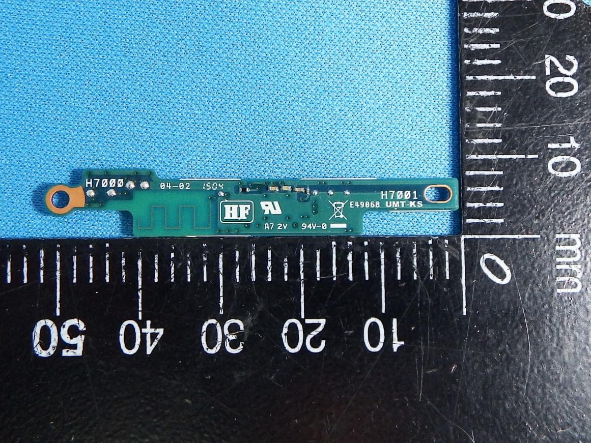
Click to zoom
Application Details
- Equipment Class
- DTS - Digital Transmission System
- Date of Grant
- Jul 13, 2015
- Application Purpose
- Original Equipment
- Date of Application
- Jul 13, 2015
- Equipment Note
- 2.4G RF Receiver
- Frequency Range
- 2402.00000000 - 2478.00000000
- Company
- PEGATRON CORPORATION
- Country
- Taiwan
Documents & Files
Document Text
Text extracted from the exhibit documents filed with the FCC. Open a document above to read the original.
Users Manual
Start Guide X-XXX-XXX-01 (1) Personal Computer VAIO ® Z Canvas VJZ12A Printed in Japan © 2015 VAIO Corporation Parts and Controls Parts and Controls on the Front ȪȩȬȫ Ȯ Ȳ Ȱ ȱ ȯ ȭ L button Air exhaust vent Built-in monaural microphone R button Built-in front camera indicator Built-in front camera Touch screen (Windows) Touch button Charge port for Keyboard Built-in stereo speaker ! Notes • Be aware that the exhaust vent may be heated while your VAIO computer is in operation. • To keep the touch screen clean and protect it from scratches, attach the wireless keyboard to your VAIO computer before carrying around the computer. For attaching the wireless keyboard, see Charging the Wireless Keyboard. Parts and Controls on the Sides ȩ Ȫ ȫ Ȭ ȭ Ȯ ȯ ȱ Ȱ Headset compatible headphone jack USB port USB port This port can be used for USB charging. SD memory card slot Mini DisplayPort output port HDMI output port LAN port Charge indicator DC IN port ȩ Ȫ ȫ Ȭ Power indicator Power button VOL (Volume) buttons Holes for attaching the pen holder Parts and Controls on the Back Ȫ ȩ ȫ Ȭ Ȯ ȭ Air intake vent Built-in rear camera Built-in rear camera indicator Air intake vent Battery off button Stand ! Notes • To lift your VAIO computer, be sure to hold both sides of the computer. Do not grab it by its stand. • When folding the stand, keep the power code and other cables out of the way. Parts and Controls of the Wireless Keyboard ȩ ȱȳȲ ȯ ȴȵ ȶ ȬȭȮȫȪ Ȱ Caps Lock key / Caps lock indicator micro USB port Function keys Power and touch pad on/off switch for Keyboard Charge port for Keyboard (on Keyboard) Charge indicator for Keyboard Charge indicator for Keyboard (located on the back) Delete key Shift key Ctrl key Fn key (Windows) key Alt key Touch pad ! Notes • The wireless keyboard has built-in magnets for attaching itself to your VAIO computer. Keep magnet-sensitive objects (credit cards, etc.) away from the keyboard to avoid possible data corruption. • Setting Airplane mode to On disables all the wireless features of your VAIO computer and you cannot connect the wireless keyboard to the computer. To use the wireless keyboard, set Airplane mode to On. Hints • There is a raised dot on the F and J keys. • For details on the keyboard shortcut keys, refer to Windows Help and Support. Safety Information and Caution • Turning off your computer with the (power) button does not disconnect the computer completely from mains voltage. To disconnect it completely, unplug the AC adapter or the power cable from mains. The socket-outlet shall be installed near the equipment and shall be easily accessible. • To prevent possible damage and risk of ignition to your computer during transportation, first attach any supplied connector covers and slot protectors in their appropriate locations, and secure the battery pack in the battery compartment if it is removable. • The supplied wireless keyboard is intended for use only with UL Listed I.T.E. computer. • To prevent fire or shock hazard, do not expose your computer to rain or moisture. • To avoid electrical shock, do not open the cabinet. Refer servicing to qualified personnel only. • Do not put your computer directly on your lap and use it for an extended period of time. The temperature of the base of the unit will rise during normal operation and over time could result in discomfort or burns. • Do not place the AC adapter in contact with your skin. Remove the AC adapter away from your body if it becomes warm and causes discomfort. • Do not block the air exhaust or intake vents while the computer is in operation. • Blocking the air vents leads to restriction on air circulation, which can cause internal overheating, resulting in deformation of the computer, a malfunction, or a fire hazard. • Observe the following precautions to provide adequate air circulation and to ensure normal reliable operation: - Do not use the computer on any cloth covered surfaces such as rugs, cushion or blankets, near draperies, or on dusty surfaces that may block its air vents. Always use the computer on flat surfaces. - Do not use the computer and/or the AC adapter while covered or wrapped in cloth. Ensure the AC adapter operates in a clear environment. - Before putting your computer in a bag, turn off the computer or place it into Sleep mode. If the computer is equipped with the power indicator, make sure the power indicator light is off. • When holding the computer, be sure to wait until it cools down. The surface around the air exhaust vent may be extremely hot. • Always keep the battery pack installed while the computer is in use. • Do not use or store your computer in a location subject to heat sources, such as radiators or air ducts; direct sunlight; excessive dust; moisture or rain; mechanical vibration or shock; strong magnets or speakers that are not magnetically shielded; excessively high and low temperatures; and high humidity. • VAIO recommends using the genuine VAIO battery pack and AC adapter that are provided with this product. If either of these items needs to be replaced during the life of the product, be sure to use a compatible genuine VAIO battery pack or AC adapter. • VAIO disclaims and shall assume no responsibility in case of any losses and damages arising from: - the use of non-genuine VAIO battery packs or AC adapters with your VAIO computer. - the disassembly, alteration of, or tampering with any VAIO battery pack. • Do not use wireless functionality on hospital premises. Doing so may cause medical devices to malfunction. • Check for and respect airline restrictions on use of wireless capabilities. If use of the wireless function is prohibited on the airline, disable all wireless connections before boarding. Open the charms by pointing to the top right corner of the screen, then move the pointer down and select the Settings charm. Select the network icon and then turn on Airplane mode.…
Text truncated - open the document above for the full version.
External Photos
FCC Test Report Report No. : FR512732-01 SPORTON International Inc. Page Number : B1 of B2 TEL : 886-3-327-3456 Report Version : Rev. 01 FAX : 886-3-327-0973 APPENDIX B. Photographs of EUT
ID Label/Location Info
1. Re FCC ID 2. R e eceiver mod D: ” VUIVJ8W eceiver modu dule label ( WRC1” ule label locat Slate RF bo tion. ard):
Internal Photos
FCC Test Report Report No. : FR512732-01 SPORTON International Inc. Page Number : B1 of B2 TEL : 886-3-327-3456 Report Version : Rev. 01 FAX : 886-3-327-0973 APPENDIX B. Photographs of EUT FCC Test Report Report No. : FR512732-01 SPORTON International Inc. Page Number : B2 of B2 TEL : 886-3-327-3456 Report Version : Rev. 01 FAX : 886-3-327-0973
RF Exposure Info
SAR Exclusion Letter Date of Issue: July 02, 2015 Page 1 Rev.00 According to KDB 447498 section 4.3.1, the 1-g SAR test exclusion thresholds at test separation distance ≤ 50 mm are determined by: [(max. power of channel, including tune-up tolerance, mW) / (min. test separation distance, mm)] *·[√f(GHz)] ≤ 3.0 The tune-up power is -1.3 dBm +/- 0dB, therefore the highest tune-up power is -1.3 dBm(0.74 mW)@ 2478 MHz When the minimum test separation distance is < 5 mm, a distance of 5 mm according to 5) in section 4.1 is applied to determine SAR test exclusion. So, (0.74mW / 5mm)* (2.478GHz ^0.5 )= 0.2 [(max. power of channel, including tune-up tolerance, mW) / (min. test separation distance, mm)] * [√f(GHz)] = 0.2 < 3.0 Therefore, standalone SAR measurements are not required for both head and body.
Test Report
FCC Test Report Report No. : FR512732-01 SPORTON INTERNATIONAL INC. Page No. : 1 of 37 TEL : 886-3-327-3456 Report Version : Rev. 02 FAX : 886-3-327-0973 FCC Test Report Equipment : 2.4G RF Receiver Brand Name : VAIO Model No. : VJ8WRC1 FCC ID : VUIVJ8WRC1 Standard : 47 CFR FCC Part 15.247 Operating Band : 2400 MHz – 2483.5 MHz FCC Classification : DTS Applicant : PEGATRON CORPORATION 5F No. 76, Ligong St.,Beitou District, Taipei City 112 Taiwan Manufacturer : Maintek Computer (Suzhou) Co., Ltd 233,Jin Feng Road,Suzhu New District, Jiangsu 215011,China The product sample received on Jun. 11, 2015 and completely tested on Jun. 26, 2015. We, SPORTON, would like to declare that the tested sample has been evaluated in accordance with the procedures given in ANSI C63.10-2009 and shown compliance with the applicable technical standards. The test results in this report apply exclusively to the tested model / sample. Without written approval of SPORTON INTERNATIONAL INC., the test report shall not be reproduced except in full. Reviewed by: Vic Hsiao / Supervisor FCC Test Report Report No. : FR512732-01 SPORTON INTERNATIONAL INC. Page No. : 2 of 37 TEL : 886-3-327-3456 Report Version : Rev. 02 FAX : 886-3-327-0973 Table of Contents 1 GENERAL DESCRIPTION .................................................................................................................... 5 1.1 Information .............................................................................................................................................. 5 1.2 Support Equipment ................................................................................................................................. 7 1.3 Testing Applied Standards ..................................................................................................................... 7 1.4 Testing Location Information .................................................................................................................. 7 1.5 Measurement Uncertainty ...................................................................................................................... 8 2 TEST CONFIGURATION OF EUT......................................................................................................... 9 2.1 The Worst Case Modulation Configuration ............................................................................................ 9 2.2 Test Channel Frequencies Configuration ............................................................................................... 9 2.3 The Worst Case Measurement Configuration ...................................................................................... 10 2.4 Test Setup Diagram ............................................................................................................................. 11 3 TRANSMITTER TEST RESULT .......................................................................................................... 13 3.1 AC Power-line Conducted Emissions .................................................................................................. 13 3.2 6dB Bandwidth ..................................................................................................................................... 16 3.3 RF Output Power .................................................................................................................................. 18 3.4 Power Spectral Density ........................................................................................................................ 21 3.5 Transmitter Bandedge Emissions ........................................................................................................ 23 3.6 Transmitter Unwanted Emissions ......................................................................................................... 26 4 TEST EQUIPMENT AND CALIBRATION DATA ................................................................................ 37 APPENDIX A. TEST PHOTOS APPENDIX B. PHOTOGRAPHS OF EUT FCC Test Report Report No. : FR512732-01 SPORTON INTERNATIONAL INC. Page No. : 3 of 37 TEL : 886-3-327-3456 Report Version : Rev. 02 FAX : 886-3-327-0973 Summary of Test Result Conformance Test Specifications Report Clause Ref. Std. Clause Description Measured Limit Result 1.1.2 15.203 Antenna Requirement Antenna connector mechanism complied FCC 15.203 Complied 3.1 15.207 AC Power-line Conducted Emissions [dBuV]: 0.1507970MHz 29.83 (Margin 26.13dB) - AV 49.82 (Margin 16.14dB) - QP FCC 15.207 Complied 3.2 15.247(a) 6dB Bandwidth 6dB Bandwidth Unit [MHz]: 1.04 ≥500kHz Complied 3.3 15.247(b) RF Output Power (Maximum Peak Conducted Output Power) Power [dBm]: 1.41 Power [dBm]:30 Complied 3.4 15.247(e) Power Spectral Density PSD [dBm/100kHz]: -19.82 PSD [dBm/3kHz]:8 Complied 3.5 15.247(d) Transmitter Bandedge Emissions Restricted Bands [dBuV/m at 3m]: 2311.020MHz 41.40 (Margin 29.60dB) - PK 28.29 (Margin 25.71dB) - AV Non-Restricted Bands: > 20 dBc Restricted Bands: FCC 15.209 Complied 3.6 15.247(d) Transmitter Unwanted Emissions Restricted Bands [dBuV/m at 3m]: 136.700MHz 35.17 (Margin 8.33dB) - PK Non-Restricted Bands: > 20 dBc Restricted Bands: FCC 15.209 Complied FCC Test Report Report No. : FR512732-01 SPORTON INTERNATIONAL INC. Page No. : 4 of 37 TEL : 886-3-327-3456 Report Version : Rev. 02 FAX : 886-3-327-0973 Revision History Report No. Version Description Issued Date FR512732-01 Rev. 02 Initial issue of report Jul. 06, 2015 2500-2690 FCC Test Report Report No. : FR512732-01 SPORTON INTERNATIONAL INC. Page No. : 5 of 37 TEL : 886-3-327-3456 Report Version : Rev. 02 FAX : 886-3-327-0973 1 General Description 1.1 Information 1.1.1 RF General Information RF General Information Frequency Range (MHz) Modulation Ch. Freq. (MHz) Channel Number Transmit Chains (N TX ) RF Output Power (dBm) 2400-2483.5 GFSK 2402-2478 2-78 [77] 1 1.41 Note 1: RF output power specifies that Maximum Peak Conducted Output Power. 1.1.2 Antenna …
Text truncated - open the document above for the full version.
Test Setup Photos
FCC Test Report Report No. : FR512732-01 SPORTON INTERNATIONAL INC. Page No. : A1 of A6 TEL : 886-3-327-3456 Report Version : Rev. 01 FAX : 886-3-327-0973 Appendix A. Test Photos 1. Photographs of Conducted Emissions Test Configuration Front view Rear view FCC Test Report Report No. : FR512732-01 SPORTON INTERNATIONAL INC. Page No. : A2 of A6 TEL : 886-3-327-3456 Report Version : Rev. 01 FAX : 886-3-327-0973 Side view FCC Test Report Report No. : FR512732-01 SPORTON INTERNATIONAL INC. Page No. : A3 of A6 TEL : 886-3-327-3456 Report Version : Rev. 01 FAX : 886-3-327-0973 2. Photographs of Radiated Emissions Test Configuration For radiated emissions 9kHz~30MHz Front view Rear view FCC Test Report Report No. : FR512732-01 SPORTON INTERNATIONAL INC. Page No. : A4 of A6 TEL : 886-3-327-3456 Report Version : Rev. 01 FAX : 886-3-327-0973 For radiated emissions 30MHz~1GHz Front view Rear view FCC Test Report Report No. : FR512732-01 SPORTON INTERNATIONAL INC. Page No. : A5 of A6 TEL : 886-3-327-3456 Report Version : Rev. 01 FAX : 886-3-327-0973 For radiated emissions above 1GHz Front view Rear view FCC Test Report Report No. : FR512732-01 SPORTON INTERNATIONAL INC. Page No. : A6 of A6 TEL : 886-3-327-3456 Report Version : Rev. 01 FAX : 886-3-327-0973 EUT take a close-up EUT take a close-up
Contact Information
Applicant
Nancy Yu(Senior Manager)
Technical Contact
Sporton International Inc.Elaine Tsai
[email protected]886-3-327-3456
No. 52, Hwa Ya 1st Rd., HwaYa · Taiwan
Non-Technical Contact
Sporton International Inc.Elaine Tsai
[email protected]886-3-327-3456
Test Firm
Sporton International Inc.Jones Tsai
Technical Specifications
| # | Rule Parts | Frequency Range | Power Output |
|---|---|---|---|
| 1 | 15C | 2.40 GHz - 2.48 GHz | 1.40 mW |
Other Applications from PEGATRON CORPORATION
VUI-TS7A01
Nov 19, 2025Hardware wallet
Equipment Class
DXX - Part 15 Low Power Communication Device TransmitterVUI-M2U350
Sep 09, 20245G FR2 ODU
Equipment Class
DTS - Digital Transmission SystemVUIPR1400-48I
Apr 14, 20245G NR O-RU N48
Equipment Class
CBD - Citizens Band Category A and B Devices
VUI-CFWM
Dec 10, 2022Customer Facing Wi-Fi Module (CFWM)
Equipment Class
NII - Unlicensed National Information Infrastructure TX
VUI-DPCP700X
May 26, 2020IP Desktop Phone
Equipment Class
DTS - Digital Transmission System