VW4A090665ATZB-24-B0 2.4GHz B0, 802.15.4/Zigbee OEM- Module
Microchip Technology Inc.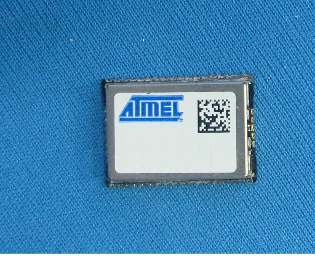
Click to zoom
Application Details
- Equipment Class
- DTS - Digital Transmission System
- Date of Grant
- May 08, 2011
- Application Purpose
- Original Equipment
- Date of Application
- May 07, 2011
- Equipment Note
- ATZB-24-B0 2.4GHz B0, 802.15.4/Zigbee OEM- Module
- Frequency Range
- 2405.00000000 - 2480.00000000
- Company
- Microchip Technology Inc.
- Country
- United States
Documents & Files
Document Text
Text extracted from the exhibit documents filed with the FCC. Open a document above to read the original.
Users Manual
8226C–MCU Wireless–09/10 ZigBit™ 2.4 GHz Wireless Modules .................................................................................................................... ATZB-24-A2/B0 Datasheet ZigBit™ 2.4 GHz Wireless Modules1-2 8226C–MCU Wireless–09/10 ZigBit™ 2.4 GHz Wireless Modulesi 8226C–MCU Wireless–09/10 Table of Contents Section 1 1.1Summary............................................................................................................................ 1-1 1.2Applications........................................................................................................................ 1-1 1.3Key Features...................................................................................................................... 1-2 1.4Benefits .............................................................................................................................. 1-2 1.5Abbreviations and Acronyms ............................................................................................. 1-2 1.6Related Documents ...........................................................................................................1-4 Section 2 2.1Overview ............................................................................................................................ 2-5 Section 3 3.1Electrical Characteristics.................................................................................................... 3-7 3.1.1Absolute Maximum Ratings ................................................................................. 3-7 3.1.2Test Conditions.................................................................................................... 3-7 3.1.3RF Characteristics ............................................................................................... 3-8 3.1.4ATmega1281V Microcontroller Characteristics ................................................... 3-8 3.1.5Module Interfaces characteristics ........................................................................ 3-8 3.2Physical/Environmental Characteristics and Outline ......................................................... 3-9 3.3Pin Configuration ............................................................................................................. 3-11 3.4Mounting Information ....................................................................................................... 3-15 3.5Sample Antenna Reference Designs............................................................................... 3-16 3.5.1General recommendations ................................................................................ 3-17 3.6Antenna specifications ..................................................................................................... 3-18 3.6.1ATZB-24-B0....................................................................................................... 3-18 3.6.2ATZB-24-A2....................................................................................................... 3-20 Section 4 4.1UNITED STATES (FCC).................................................................................................. 4-22 4.2EUROPEAN UNION (ETSI)............................................................................................. 4-23 4.3Approved Antenna List..................................................................................................... 4-24 Section 5 5.1Ordering Information ........................................................................................................5-25 ZigBit™ 2.4 GHz Wireless Modules1-1 8226C–MCU Wireless–09/10 Section 1 Introduction 1.1Summary ZigBit ™ is an ultra-compact, low-power, high-sensitivity 2.4 GHz IEEE 802.15.4/ZigBee ® OEM module based on the innovative Atmel’s mixed-signal hardware platform. It is designed for wireless sensing, control and data acquisition applications. ZigBit modules eliminate the need for costly and time-consum- ing RF development, and shortens time to market for a wide range of wireless applications. Two different versions of 2.4 GHz ZigBit modules are available: ATZB-24-B0 module with balanced RF port for applications where the benefits of PCB or external antenna can be utilized and ATZB-24-A2 module with dual chip antenna satisfying the needs of applications requiring integrated, small-footprint antenna design. 1.2Applications ZigBit module is compatible with robust IEEE 802.15.4/ZigBee stack that supports a self-healing, self- organizing mesh network, while optimizing network traffic and minimizing power consumption. Atmel offers two stack configurations: BitCloud and SerialNet. BitCloud is a ZigBee PRO certified software development platform supporting reliable, scalable, and secure wireless applications running on Atmel’s ZigBit modules. SerialNet allows programming of the module via serial AT-command interface. The applications include, but are not limited to: • Building automation & monitoring – Lighting controls – Wireless smoke and CO detectors – Structural integrity monitoring •HVAC monitoring & control •Inventory management •Environmental monitoring •Security •Water metering •Industrial monitoring – Machinery condition and performance monitoring – Monitoring of plant system parameters such as temperature, pressure, flow, tank level, humidity, vibration, etc. •Automated meter reading (AMR) Introduction ZigBit™ 2.4 GHz Wireless Modules1-2 8226C–MCU Wireless–09/10 1.3Key Features •Ultra compact size (24 x 13.5 x 2.0 mm for ATZB-24-A2 module and 18.8 x 13.5 x 2.0 mm for ATZB-24-B0 module) •Innovative (patent-pending) balanced dual chip antenna design with antenna gain of approximately 0 dBi (for ATZB-24-A2 version) •High RX sensitivity (-101 dBm) •Outperforming link budget (104 dB) •Up to 3 dBm output power •Very low power consumption: – < 6 μA in Sleep mode, – 19 mA in RX mode, – 18 mA in TX mode •Ample memory resources (128K bytes of flash memory, 8K bytes RAM, 4K bytes EEPROM) •W…
Text truncated - open the document above for the full version.
Users Manual
FCC Certification Scenarios for Atmel ZigBits on Customers' products Features • Covers FCC certification scenarios for Atmel ZigBits’ usage • Analyzes the custom products possibilities and likely-hoods for successful certification 1 Introduction Atmel’s Wireless applications play vital role in providing IEEE 802.15.4 – compliant, ZigBee, and 6LoWPAN wireless solutions using family of RF devices such as ZigBits, AT86RFxxx,and MegaRF single chip solutions. These devices are purely based on Atmel’s wide range of high performance, low-power IEEE 802.15.4-compliant transceivers for the regional 700/800/900MHz frequency bands available in Europe and North America, and the 2.4GHz band available world wide. 8-bit Microcontrollers Application Note Rev. [0.5]-AVR-[09/10] 2 AVR[appn ote nr] [doc nr]-AVR-[mm]/[yy] 2 Overview This application note describes an overview of the Certification Scenarios possible when a designer uses the Atmel ZigBits portfolio. It also covers the changes that affect Atmel’s existing certification due to minor or major changes on designer’s hardware. 3 Atmel’s Range of ZigBit Modules and usage scenarios in customer products 3.1 ATZB-24-A2 It is a ZigBit Module with Dual Chip Antenna, a low-power, 802.15.4 ZigBee module combination with the popular ATmega1281V MCU and the Atmel AT86RF230 radio transceiver. The ATZB-24-A2 comes with a Dual Chip Antenna and eliminates the need for costly and time-consuming RF development and shortens time to market, while embedded 802.15.4/ZigBee software ensures standards-based wireless connectivity for a wide range of applications. Figure 3-1. ATZB-24-A2 3.1.1 Certification scenarios The following scenario explains the usage of the ATZB-24-A2 module with the customer’s base board. 3.1.2 Scenario # 1 The ATZB-24-A2 module is bought by a designer and used on the base board. When designers use the ATZB-24-A2 module on their base board and if the product does not have any other radiating circuits, the designer need not re-certify the complete product. In this case the designer has to mention on a visible area in their product that “Product carries FCC module with FCC ID – VW4A090664”. AVR[appnote nr] 3 [doc nr]-AVR-[mm]/[yy] 3.1.3 Scenario # 2 When designers use the ATZB-24-A2 module on their base board and if there are additional circuits on the base board, with the additionally added circuits comprising of another radio or switching circuits, the radiations caused by the new circuits may or may not affect the performance of the ATZB-24-A2. If the ATZB-24-A2 does not get affected by the additional circuits, still there are possibilities that there could be emissions from these circuits that are out of limits specified by part 15.247. If these additional circuits are designed to operate within compliance limits, then the probability of successful certification is high. For more information on the type of additional circuits, please refer appendix A. The FCC ID of ATZB-24-A2 is VW4A090664. Customers have to mention “Product carries Module with FCC ID VW4A090664” on their product containing the ATZB-24- A2 ZigBits. The ZigBit’s FCC ID cannot be used in replacement of the final product’s FCC ID, if there is a requirement to have separate FCC ID for the entire product. 3.2 ATZB-A24-UFL ZigBit Amp ATZB-A24-UFL is an amplified IEEE 802.15.4/ZigBee module. Its unique RF design achieves a rare combination of the industry-leading range performance and low power consumption. The ATZB-A24-UFL module’s small footprint of less than a square inch of space makes the integration easy, with the built-in U.FL antenna connector. Figure 3-2. ATZB-A24-UFL 3.2.1 Certification scenarios The following scenarios explain the usage of the ATZB-A24-UFL module on customer’s base board. 3.2.2 Scenario # 1 The ATZB-A24-UFL module is bought by a designer and used on the base board. When a designer uses ATZB-A24-UFL module on a base board with an antenna whose gain is less than or equal to 0dBi, and if the product does not have any other radiating circuit, the designer need not get the product re-certified. In this case the designer has to mention on a visible area of the product that “Product carries module FCC ID VW4A090668” 4 AVR[appn ote nr] [doc nr]-AVR-[mm]/[yy] If there are additional circuits on the base board, with the additionally added circuits comprising of another radio or switching circuits, the radiations caused by the new circuits may or may not affect the performance of the ATZB-A24-UFL. If the ATZB- A24-UFL does not get affected by the additional circuits, still there are possibilities that there could be emissions from these circuits that are out of limits specified by part 15.247. If these additional circuits are designed to operate within compliance limits, then the probability of successful certification is high. For more information please refer appendix A. 3.2.3 Scenario # 2 Designers may want to use the ATZB-A24-UFL on the base board and / or use UFL antenna adaptor and take out the RF signal to a different antenna connector. Sometimes customers may have requirement to use higher gain antenna than an antenna with 0dBi gain as mentioned in sec 3.2.2. In such case designer is expected to re-certify the product with FCC and ETSI. In addition to having a different antenna and/or connector, there may be radiating circuits on the base board which will call for re-certification. Refer appendix A. for detailed information about additional circuits on base board. The FCC ID of ATZB-A24-UFL is VW4A090668. Customers have to mention “Product carries Module with FCC ID VW4A090668” on their product containing the ATZB- A24-UFL ZigBits. The ZigBit’s FCC ID cannot be used in replacement of the final product’s FCC ID, if there is a requirement to have separate FCC ID for the entire product. 3.3 ATZB-24-B0 ATZB-24-B0 ZigBit Module with Balanced RF Output is a low-power, 802.15.4/ ZigBee module, combination of the ATmega1281V MCU and the AT86RF230 radio transceiver. ATZ…
Text truncated - open the document above for the full version.
Attestation Statements
Atmel Norway AS Vestre Rosten 79, 7075 Tiller, Norway Tlf:+47 72 88 43 88 Fax +47 72 88 43 99 15 th April 2011 Federal Communications Commission 7435 Oakland Mills Road Columbia, MD 21046 Re: FCC ID: VW4A090665 To Whom It May Concern: Atmel Norway AS, certifies that neither the applicant nor any party to this application, as defined in 47 CFR Ch. 1.2002(b), is subject to a denial to Federal benefits, that include FCC benefits, pursuant to section 5301 of the Anti-Drug Abuse Act of 1998, 21 U.S.C. 835(a). This authorization is valid until further written notice from Atmel Norway AS Sincerely, Saravanakumar Marudhachalam Atmel Norway AS Vestre Rosten 79 7075 Tiller Norway
Attestation Statements
Atmel Norway AS Vestre Rosten 79, 7075 Tiller, Norway Tlf:+47 72 88 43 88 Fax +47 72 88 43 99 5 th May 2011 TO: FCC Authorization & Evaluation Division 7435 Oakland Mills Road Columbia, MD 21045-0429 Subject: Declaration Letter for professional installation for ATZB-24-B0 To Whom It May Concern: ATZB-24-B0 ZigBit is an ultra-compact, low-power, high-sensitivity 2.4 GHz. IEEE 802.15.4 / ZigBee OEM module based on the innovative Atmel’s mixed-signal hardware platform, designed for wireless sensing, control and data acquisition applications. ATMEL NORWAY AS declares that ATZB-24-B0 requires a special set of skills for installation and configuration i.e. checking signal strength before installation using proprietary tool for wireless network within the building for best performance. Hence, this device cannot be sold to general public through retail or by mail order. Sincerely, Saravanakumar Marudhachalam Staff Engineer, Atmel Norway AS
Cover Letter(s)
Atmel Norway AS Vestre Rosten 79, 7075 Tiller, Norway Tlf:+47 72 88 43 88 Fax +47 72 88 43 99 15 th April 2011 To: Federal Communications Commission Authorization and Evaluation Division Confidentiality Request regarding application for certification of FCC ID: VW4A090665 Pursuant to Sections 0.457 and 0.459 of the Commission’s Rules, we hereby request confidential treatment of information accompanying this application as outlined below: Exhibit Type File Name 1. Schematic diagram 2. PCB design 3. Bill of Material ATZB-24-B0-FCC-Schematic Prints A09-0665.pdf ATZB-24-B0-FCC-PCB Prints A09-0665.pdf Atmel BOM ATZB-24-B0 A09-0665.doc Further, we seek short term confidentiality on the following documents: Exhibit Type File Name 4. External and Internal photographs 5. Test setup photographs 1. ATZB-24-B0 Photos 2. ATZB-24-B0 Test Setup Photos The above materials contain trade secrets and proprietary information not customarily released to the public. The public disclosure of these materials may be harmful to the applicant and provide unjustified benefits to its competitors. The applicant understands that pursuant to Section 0.457 of the Rules, disclosure of this application and all accompanying documentation will not be made before the date of the Grant for this application. Sincerely, Saravanakumar Marudhachalam Atmel Norway AS
Cover Letter(s)
Atmel Norway AS Vestre Rosten 79, 7075 Tiller, Norway Tlf:+47 72 88 43 88 Fax +47 72 88 43 99 Applicant/Grantee Atmel FCC ID: VW4A090665 Section 15.212 Modular Transmitters Request for Single Modular Approval □ Request for Limited Single Modular approval ◙ SI.no Requirements EUT Conditions Comply (Y/N) 01 The radio elements of the modular transmitter must have their own Shielding. The physical crystal and tuning capacitors may be located external to the shielded radio elements The module has its own RF shielding. Shield Can is employed on the board structure, , Refer EUT External Photos Y 02 The modular transmitter must have buffered modulation/data inputs (if such inputs are provided) to ensure that the module will comply with Part 15 requirements under conditions of excessive data rates or over-modulation All modulation and data input(s) are Buffered. Refer Block Diagram and schematic Diagram. Y 03 The modular transmitter must have its Own power supply regulation. The AT86RF230 RF Transceiver IC has internal regulator as shown in the IC internal Block diagram (Please See Block Diagram- Appendix 5) Please refer to Blocks AVREG and DVREG which are Analog Domain 1.8V regulator and Digital Domain 1.8V regulator, respectively. Y 04 The modular transmitter must comply with the antenna and transmission system requirements of Sections 15.203, 15.204(b) and 15.204(c). The antenna must either be permanently attached or employ a “unique” antenna coupler (at all connections between the module and The antenna, including the cable). The “professional installation” provision of Section 15.203 is not applicable to modules but can apply to limited Modular approvals under paragraph (b) of this section. Refer User manual, Section 3.6.2, fig 3-12 N 05 The modular transmitter must be tested in a stand-alone configuration, i.e., the module must not be inside another device during testing for compliance With Part 15 requirements. Unless the transmitter module will be battery powered, it must comply with the AC Refer test setup photos Y Atmel Norway AS Vestre Rosten 79, 7075 Tiller, Norway Tlf:+47 72 88 43 88 Fax +47 72 88 43 99 line conducted requirements found in Section 15.207. AC or DC power lines and data input/output lines connected to the module must not contain ferrites, unless they will be marketed with the Module (see Section 15.27(a)). The length of these lines shall be the length typical of actual use or, if that length is unknown, at least 10 centimeters to insure that there is no coupling between the case of the module and supporting Equipment. Any accessories, peripherals, or support equipment connected to the module during testing shall be Unmodified and commercially available (see Section 15.31(i)). 06 The modular transmitter must be equipped with either a permanently affixed label or must be capable of electronically displaying its FCC Identification number. (A) If using a permanently affixed label, the modular transmitter must be labeled with its own FCC identification number, and, if the FCC identification number is not visible when the module is installed inside another device, then the outside of the device into which the module is installed must also display a label referring to The enclosed module. This exterior label can use wording such as the following: “Contains Transmitter Module FCC ID: XYZMODEL1” or “Contains FCC ID: XYZMODEL1.” Any similar wording That expresses the same meaning may be used. The Grantee may either provide such a label, an example of which must be included in the application for equipment authorization, or, must provide adequate instructions along with the module which explain This requirement. In the latter case, a copy of these instructions must be included in the Application for equipment authorization. (B) If the modular transmitter uses an electronic display of the FCC identification number, the information must be readily accessible and visible on the modular transmitter or on the Labeled with its own FCC ID number. Refer Label information Y Atmel Norway AS Vestre Rosten 79, 7075 Tiller, Norway Tlf:+47 72 88 43 88 Fax +47 72 88 43 99 Device in which it is installed. If the module is installed inside another device, then the outside of the device into which the module is installed must display a label referring to the enclosed Module. This exterior label can use wording such as the following: “Contains FCC certified transmitter module(s).” Any similar wording that expresses the same Meaning may be used. The user manual must include instructions on how to access the Electronic display. A copy of these instructions Must be included in the application for equipment authorization. 07 The modular transmitter must comply with any specific rules or operating requirements that ordinarily apply to a complete transmitter and the manufacturer must provide adequate instructions along with the module to explain any such requirements. A copy of these Instructions must be included in the application for equipment authorization. The EUT is compliant with all Applicable FCC rules. Detail instructions for maintaining compliance are given in The OEM Manual. Refer User manual. Y 08 The modular transmitter must comply with any applicable RF exposure requirements in its final configuration The EUT is compliant with all Applicable RF exposure requirements. Refer Maximum permissible Exposure Information Y A limited modular approval may be granted for single or split modular transmitters that do not comply with all of the above requirements, e.g., shielding, minimum signaling amplitude, buffered modulation/data inputs, or power supply regulation, if the manufacturer can demonstrate by alternative means in the application for equipment authorization that the modular transmitter meets all the applicable Part 15 requirements under the operating conditions in which the transmitter will be used. Limited modular approval also may be granted in those instances where compliance with RF exp…
Text truncated - open the document above for the full version.
External Photos
www.tuv.com Appendix 2 Prüfbericht - Nr.: Test Report No. 02423094 001 Seite 1 von 4 Page 1 of 4 Overall View Top View www.tuv.com Appendix 2 Prüfbericht - Nr.: Test Report No. 02423094 001 Seite 2 von 4 Page 2 of 4 Bottom View Dimensional View www.tuv.com Appendix 2 Prüfbericht - Nr.: Test Report No. 02423094 001 Seite 3 von 4 Page 3 of 4 Dimensional View Module Top View www.tuv.com Appendix 2 Prüfbericht - Nr.: Test Report No. 02423094 001 Seite 4 von 4 Page 4 of 4 Module Bottom View
ID Label/Location Info
www.tuv.com Appendix 4 Prüfbericht - Nr.: Test Report No. 02423094 001 Seite 1 von 1 Page 1 of 1 Label Diagram Location Diagram Label Location
Internal Photos
www.tuv.com Appendix 3 Prüfbericht - Nr.: Test Report No. 02423094 001 Seite 1 von 3 Page 1 of 3 Module with Enclosure removed Inner View of Enclosure www.tuv.com Appendix 3 Prüfbericht - Nr.: Test Report No. 02423094 001 Seite 2 von 3 Page 2 of 3 Module with Enclosure Bottom View of Module www.tuv.com Appendix 3 Prüfbericht - Nr.: Test Report No. 02423094 001 Seite 3 von 3 Page 3 of 3 RF Connector-Top View RF Connector-Bottom View
RF Exposure Info
www.tuv.com Appendix 10 Prüfbericht - Nr.: Test Report No. 02423094 001 Seite 1 von 1 Page 1 of 1 Radio Frequency Human Exposure Evaluation: The highest RF output power of the EUT at 2405 MHz was measured 4.56 dBm which is less than 20mW. Since maximum peak output power of the transmitter is <60/f (GHz) mW, i.e. 2.85mW<24.94(=60/2405) mW, hence the EUT is excluded from SAR evaluation according to FCC KDB publication 447498 D01: Mobile Portable RF Exposure.
Test Report
Produkte Products TÜV Rheinland LGA Products GmbH Tillystraße 2 D - 90431 Nürnberg Tel.: +49 911 655 5225 Fax: +49 911 655 5226 Mail: [email protected] Web: www.tuv.com Rev.:1.2 2009-12-29 / approved: M.Jungnitsch Prüfbericht - Nr.: 02423094 001 Seite 1 von 24 Test Report No.: Page 1 of 24 Auftraggeber: Client: Atmel Norway AS Vestre Rosten 79 7075 Tiller Norway Gegenstand der Prüfung: Test item: Zigbit 2.4GHz Balanced Output Bezeichnung: Identification: ATZB-24-B0 Serien-Nr.: Serial No. Engineering Sample Wareneingangs-Nr.: Receipt No.: 1403014281 Eingangsdatum: Date of receipt: 06.04.2011 Prüfort: Testing location: Refer Page 4 of 24 for test facilities Prüfgrundlage: Test specification: FCC 15, Subpart C Prüfergebnis: Test Result: Der Prüfgegenstand entspricht oben genannter Prüfgrundlage(n). The tests item passed the test specification(s). Prüflaboratorium: Testing Laboratory: TÜV Rheinland (India) Pvt. Ltd. Alpha Tower, Sigma Soft Tech Park, # 7, Whitefield Main Road, Varthur Kodi, Bangalore – 560066, India geprüft / tested by: kontrolliert / reviewed by: 20.04.2011 Vinay.N Test Engineer 21.04.2011 Varma Kalyan Manager Datum Date Name/Stellung Name/Position Unterschrift Signature Datum Date Name/Stellung Name/Position Unterschrift Signature Sonstiges /Other Aspects: FCC ID : VW4A090665 Abkürzungen: P(ass) = entspricht Prüfgrundlage F(ail) = entspricht nicht Prüfgrundlage N/A = nicht anwendbar N/T = nicht getestet Abbreviations: P(ass) = passed F(ail) = failed N/A = not applicable N/T = not tested Dieser Prüfbericht bezieht sich nur auf das o.g. Prüfmuster und darf ohne Genehmigung der Prüfstelle nicht auszugsweise vervielfältigt werden. Dieser Bericht berechtigt nicht zur Verwendung eines Prüfzeichens. This test report relates to the a. m. test sample. Without permission of the test center this test report is not permitted to be duplicated in extracts. This test report does not entitle to carry any safety mark on this or similar products. www.tuv.com Test Report No.:02423094 001 Date: 20.04.2011 Page 2 of 24 Test Result Summary Clause Test Item Result 15.247(b)(3) Conducted Peak RF Output Power Pass 15.247 (a)(2) 6dB Bandwidth Pass 15.247(e) Power Spectral Density Pass 15.247(d) Band-edge Compliance Pass 15.209 Spurious Radiated Emissions Pass www.tuv.com Test Report No.:02423094 001 Date: 20.04.2011 Page 3 of 24 Content List of Test and Measurement Instruments .............................................................. 4 General Product Information ..................................................................................... 5 Product Function and Intended Use ............................................................................................. 5 Ratings and System Details ........................................................................................................... 5 Operation Descriptions .............................................................................................. 6 Test Set-up and Operation Mode ............................................................................... 7 Principle of Configuration Selection ............................................................................................ 7 Test Operation and Test Software ................................................................................................ 7 Special Accessories and Auxiliary Equipment ............................................................................ 7 Countermeasures to achieve EMC Compliance .......................................................................... 7 Test Methodology ....................................................................................................... 8 Radiated Emission Test ................................................................................................................. 8 Test Results ................................................................................................................. 9 Conducted Peak Output Power Section 15.247(b)(3) ........................... 9 6 dB Bandwidth Section 15.247(a)(2) ......................... 12 Power Spectral Density Section 15.247(e) ............................ 16 Band-edge Compliance Section 15.247 (d) ............................ 19 Spurious Radiated Emissions Section 15.209 ................................. 23 Appendix 1: Test Setup Photos Appendix 2: External Photos Appendix 3: Internal Photos Appendix 4: Label Diagram Appendix 5: Block Diagram Appendix 6: Specification of EUT Appendix 7: Schematic Diagrams Appendix 8: Bill of Material Appendix 9: User Manual Appendix 10: Maximum Permissible Exposure Information www.tuv.com Test Report No.:02423094 001 Date: 20.04.2011 Page 4 of 24 List of Test and Measurement Instruments Wipro Technologies, Bangalore List of Test and Measurements Equipment Manufacturer Type S/N Calibration Due Date EMI Test Receiver Rohde & Schwarz ESIB40 100306 24.03.2012 Hybrid Log Periodic Antenna TDK HLP3003C 130334 21.03.2012 Broadband Horn Antenna Schwarzbeck Mess-Electronik BBHA9170 9170-344 21.03.2012 Double Ridged Horn Antenna Schwarzbeck Mess-Electronik BBHA9120D 9120D- 687 21.03.2012 Pre-Amplifier TDK-RFSolution PA-02 100008 15.02.2012 Testing Facilities 1) Wipro Technologies Survey No. 70, 77, 78 / 8A, Dodda Kannelli, Sarjapur Road, Bangalore – 560 035 India www.tuv.com Test Report No.:02423094 001 Date: 20.04.2011 Page 5 of 24 General Product Information Product Function and Intended Use 2.4GHz. Balanced Output ATZB-24-B0 Zigbit is an ultra-compact, low-power, high-sensitivity 2.4GHz. IEEE 802. 15.4 / Zigbee OEM Module based on innovative Atmel’s mixed-signal hardware platform designed for wireless sensing, control and data acquisition applications. Ratings and System Details Test Conditions: 5 V DC (from USB) Environmental conditions: Temperature: +23 º C RH: 62% Operating Frequency 2400 – 2483.5MHz No. of channel 16 Channel Spacing 5 MHz Transmitted Power +5 dBm Modulation DSSS …
Text truncated - open the document above for the full version.
Test Setup Photos
www.tuv.com Appendix 1 Prüfbericht - Nr.: Test Report No. 02423094 001 Seite 1 von 2 Page 1 of 2 Test setup Test setup www.tuv.com Appendix 1 Prüfbericht - Nr.: Test Report No. 02423094 001 Seite 2 von 2 Page 2 of 2 Test setup
Contact Information
Applicant
Steve Caldwell(Vice President, Wireless Solutions Group)
Test Firm
TARANGSatheesh I
Technical Specifications
| # | Rule Parts | Frequency Range | Power Output |
|---|---|---|---|
| 1 | 15C | 2.40 GHz - 2.48 GHz | 2.90 mW |
Other Applications from Microchip Technology Inc.
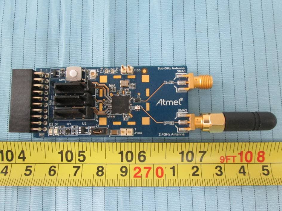
VW4A091980
Dec 22, 2015ATREB215-XPRO
Equipment Class
DXX - Part 15 Low Power Communication Device TransmitterVW4A092412
Mar 27, 2015ATSAMR21ZLL-EK
Equipment Class
DTS - Digital Transmission System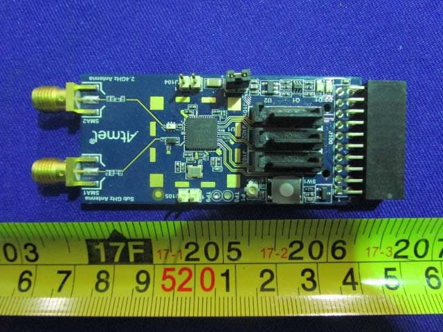
VW4A091982
Mar 21, 2015ATREB215-XPRO
Equipment Class
DTS - Digital Transmission System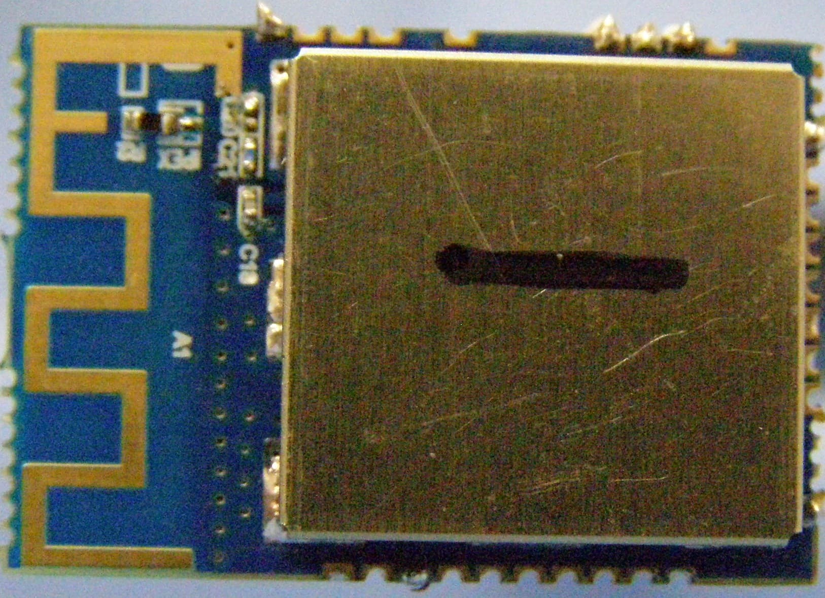
VW4ATWILC1000
Dec 03, 2014Wireless Module
Equipment Class
DTS - Digital Transmission System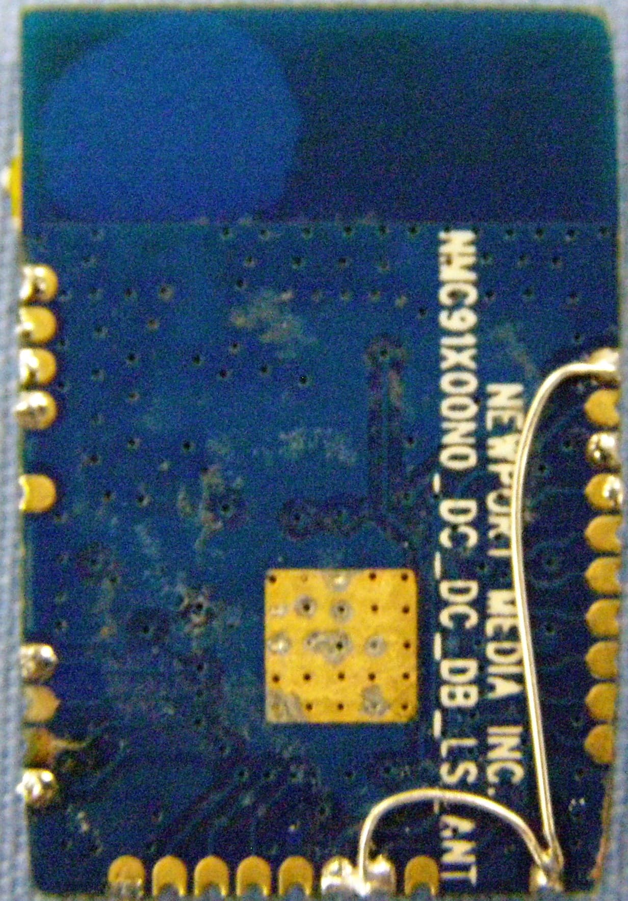
VW4ATWINC1500
Nov 17, 2014Wireless Module
Equipment Class
DTS - Digital Transmission System