VW4A090668Zigbit Amp 2.4GHz, UFL
Microchip Technology Inc.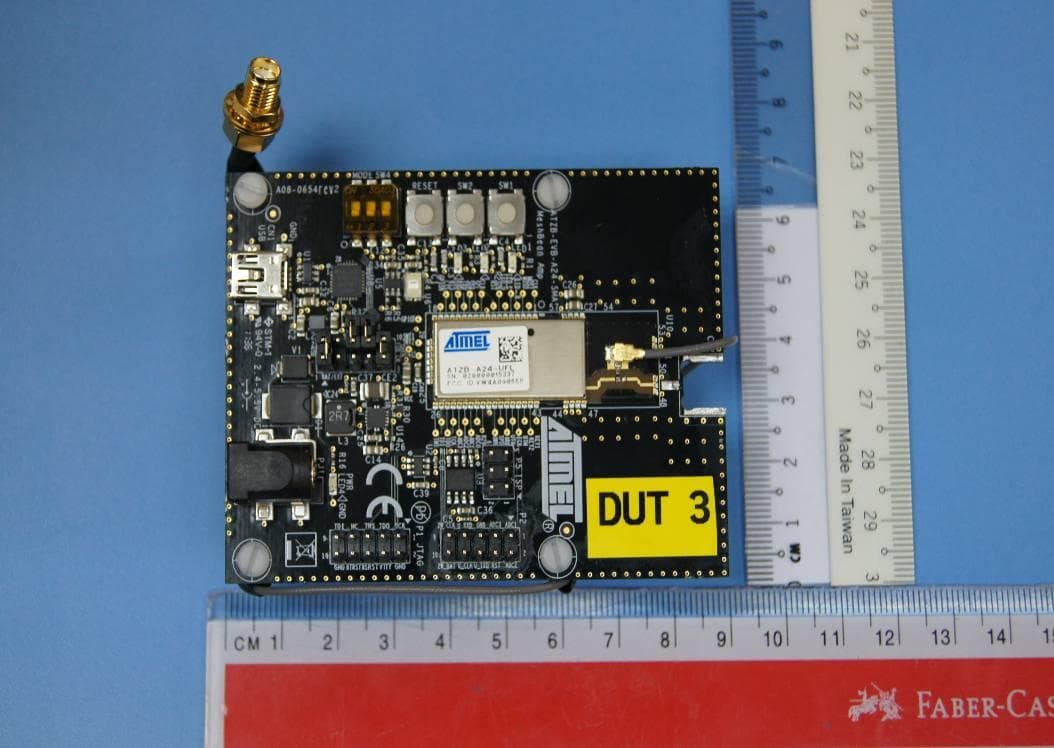
Click to zoom
Application Details
- Equipment Class
- DSS - Part 15 Spread Spectrum Transmitter
- Date of Grant
- Feb 09, 2012
- Application Purpose
- Original Equipment
- Date of Application
- Feb 08, 2012
- Equipment Note
- Zigbit Amp 2.4GHz, UFL
- Frequency Range
- 2405.00000000 - 2480.00000000
- Company
- Microchip Technology Inc.
- Country
- United States
Documents & Files
Document Text
Text extracted from the exhibit documents filed with the FCC. Open a document above to read the original.
Users Manual
8228C–MCU Wireless–09/10 ZigBit™ 2.4 GHz Amplified Wireless Modules ................................................................................................................... ATZB-A24-UFL/U0 Datasheet ZigBit™ 2.4 GHz Amplified Wireless Modules1-2 8228C–MCU Wireless–09/10 ZigBit™ 2.4 GHz Amplified Wireless Modulesi 8228B–MCU Wireless–06/09 Table of Contents Section 1 1.1Summary............................................................................................................................ 1-1 1.2Applications........................................................................................................................ 1-1 1.3Key Features...................................................................................................................... 1-2 1.4Benefits .............................................................................................................................. 1-2 1.5Abbreviations and Acronyms ............................................................................................. 1-2 1.6Related Documents ...........................................................................................................1-4 Section 2 2.1Overview ............................................................................................................................ 2-5 Section 3 3.1Electrical Characteristics.................................................................................................... 3-7 3.1.1Absolute Maximum Ratings ................................................................................. 3-7 3.1.2Test Conditions.................................................................................................... 3-7 3.1.3RF Characteristics ............................................................................................... 3-8 3.1.4ATmega1281V Microcontroller Characteristics ................................................... 3-8 3.1.5Module Interfaces characteristics ........................................................................ 3-8 3.2Physical/Environmental Characteristics and Outline ......................................................... 3-9 3.3Pin Configuration ............................................................................................................. 3-10 3.4Mounting Information ....................................................................................................... 3-14 3.5Soldering Profile............................................................................................................... 3-14 3.6Antenna Reference Design.............................................................................................. 3-15 Section 4 4.1Ordering Information ........................................................................................................4-16 ZigBit™ 2.4 GHz Amplified Wireless Modules1-1 8228B–MCU Wireless–06/09 Section 1 Introduction 1.1Summary ZigBit™ Amp is an ultra-compact, extended range, low-power, high-sensitivity 2.4GHz IEEE 802.15.4/ZigBee ® OEM module from Atmel. Based on the innovative Atmel's mixed-signal hard- ware platform, this module is enhanced by an output power amplifier and an input low-noise amplifier, and is designed for wireless sensing, monitoring & control and data acquisition applications. ZigBit Amp modules eliminate the need for costly and time-consuming RF development, and shortens time to mar- ket for wireless applications with extended range requirements. Two different versions of ZigBit 2.4 GHz Amplified modules are available: ATZB-A24-UFL with built-in U.FL antenna connector and the ATZB-A24-U0 with unbalanced RF output. These modules are an addi- tion to the ZigBit family represented by ATZB-24-A2 and ATZB-24-B0. In addition Atmel offer the ZigBit 900 MHz Wireless Module ATZB-900-B0 [2]. 1.2Applications ZigBit module is compatible with robust IEEE 802.15.4/ZigBee stack that supports a self-healing, self- organizing mesh network, while optimizing network traffic and minimizing power consumption. Atmel offers two stack configurations: BitCloud and SerialNet. BitCloud is a ZigBee PRO certified software development platform supporting reliable, scalable, and secure wireless applications running on Atmel’s ZigBit modules. SerialNet allows programming of the module via serial AT-command interface. The applications include, but are not limited to: • Building automation & monitoring – Lighting controls – Wireless smoke and CO detectors – Structural integrity monitoring •HVAC monitoring & control •Inventory management •Environmental monitoring •Security •Water metering •Industrial monitoring – Machinery condition and performance monitoring – Monitoring of plant system parameters such as temperature, pressure, flow, tank level, humidity, vibration, etc. •Automated meter reading (AMR) Introduction ZigBit™ 2.4 GHz Amplified Wireless Modules1-2 8228B–MCU Wireless–06/09 1.3Key Features •Ultra compact size (38.0 x 13.5 x 2.0 mm) •High RX sensitivity (-104 dBm) •Outperforming link budget (up to 124 dB) •Up to +20 dBm output power •Very low power consumption: – < 6 μA in Sleep mode, – 23 mA in RX mode, – 50 mA in TX mode •Ample memory resources (128K bytes of flash memory, 8K bytes RAM, 4K bytes EEPROM) •Wide range of interfaces (both analog and digital): – 9 spare GPIO, 2 spare IRQ lines – 4 ADC lines + 1 line for supply voltage control (up to 9 lines with JTAG disabled) – UART with CTS/RTS control –USART –I2C – SPI –1-Wire – Up to 30 lines configurable as GPIO •Capability to use MAC address written into EEPROM •IEEE 802.15.4 compliant transceiver •2.4 GHz ISM band •BitCloud embedded software, including serial bootloader and AT command set 1.4Benefits •Extended range through additional PA and LNA •Ultra low power consumption combined with unprecedented range •Rapid design-in with built-in U.FL connector (ATZB-A24-UFL) •Flexibility in using a different external antenna for every application •Sm…
Text truncated - open the document above for the full version.
Users Manual
FCC Certification Scenarios for Atmel ZigBits on Customers' products Features • Covers FCC certification scenarios for Atmel ZigBits’ usage • Analyzes the custom products possibilities and likely-hoods for successful certification 1 Introduction Atmel’s Wireless applications play vital role in providing IEEE 802.15.4 – compliant, ZigBee, and 6LoWPAN wireless solutions using family of RF devices such as ZigBits, AT86RFxxx,and MegaRF single chip solutions. These devices are purely based on Atmel’s wide range of high performance, low-power IEEE 802.15.4-compliant transceivers for the regional 700/800/900MHz frequency bands available in Europe and North America, and the 2.4GHz band available world wide. 8-bit Microcontrollers Application Note Rev. [0.5]-AVR-[09/10] 2 AVR[appn ote nr] [doc nr]-AVR-[mm]/[yy] 2 Overview This application note describes an overview of the Certification Scenarios possible when a designer uses the Atmel ZigBits portfolio. It also covers the changes that affect Atmel’s existing certification due to minor or major changes on designer’s hardware. 3 Atmel’s Range of ZigBit Modules and usage scenarios in customer products 3.1 ATZB-24-A2 It is a ZigBit Module with Dual Chip Antenna, a low-power, 802.15.4 ZigBee module combination with the popular ATmega1281V MCU and the Atmel AT86RF230 radio transceiver. The ATZB-24-A2 comes with a Dual Chip Antenna and eliminates the need for costly and time-consuming RF development and shortens time to market, while embedded 802.15.4/ZigBee software ensures standards-based wireless connectivity for a wide range of applications. Figure 3-1. ATZB-24-A2 3.1.1 Certification scenarios The following scenario explains the usage of the ATZB-24-A2 module with the customer’s base board. 3.1.2 Scenario # 1 The ATZB-24-A2 module is bought by a designer and used on the base board. When designers use the ATZB-24-A2 module on their base board and if the product does not have any other radiating circuits, the designer need not re-certify the complete product. In this case the designer has to mention on a visible area in their product that “Product carries FCC module with FCC ID – VW4A090664”. AVR[appnote nr] 3 [doc nr]-AVR-[mm]/[yy] 3.1.3 Scenario # 2 When designers use the ATZB-24-A2 module on their base board and if there are additional circuits on the base board, with the additionally added circuits comprising of another radio or switching circuits, the radiations caused by the new circuits may or may not affect the performance of the ATZB-24-A2. If the ATZB-24-A2 does not get affected by the additional circuits, still there are possibilities that there could be emissions from these circuits that are out of limits specified by part 15.247. If these additional circuits are designed to operate within compliance limits, then the probability of successful certification is high. For more information on the type of additional circuits, please refer appendix A. The FCC ID of ATZB-24-A2 is VW4A090664. Customers have to mention “Product carries Module with FCC ID VW4A090664” on their product containing the ATZB-24- A2 ZigBits. The ZigBit’s FCC ID cannot be used in replacement of the final product’s FCC ID, if there is a requirement to have separate FCC ID for the entire product. 3.2 ATZB-A24-UFL ZigBit Amp ATZB-A24-UFL is an amplified IEEE 802.15.4/ZigBee module. Its unique RF design achieves a rare combination of the industry-leading range performance and low power consumption. The ATZB-A24-UFL module’s small footprint of less than a square inch of space makes the integration easy, with the built-in U.FL antenna connector. Figure 3-2. ATZB-A24-UFL 3.2.1 Certification scenarios The following scenarios explain the usage of the ATZB-A24-UFL module on customer’s base board. 3.2.2 Scenario # 1 The ATZB-A24-UFL module is bought by a designer and used on the base board. Atmel’s ATZB-A24-UFL Module has been certified under Limited Modular category of FCC part 15 subpart C, limited modular certification applies to modules that do not fully meet the requirements for a single modular certification. Host-manufacturer must ensure that the end-user of the host that will finally carry the module has no access to 4 AVR[appn ote nr] [doc nr]-AVR-[mm]/[yy] the antenna connectors, because they are standard connectors. The position of the Antenna cable is not really fixed as part of this product, and hence the module must be re-certified. If there are additional circuits on the base board, with the additionally added circuits comprising of another radio or switching circuits, the radiations caused by the new circuits may or may not affect the performance of the ATZB-A24-UFL. If the ATZB- A24-UFL does not get affected by the additional circuits, still there are possibilities that there could be emissions from these circuits that are out of limits specified by part 15.247. If these additional circuits are designed to operate within compliance limits, then the probability of successful certification is high. For more information please refer appendix A. 3.2.3 Scenario # 2 Designers may want to use the ATZB-A24-UFL on the base board and / or use UFL antenna adaptor and take out the RF signal to a different antenna connector. Sometimes customers may have requirement to use higher gain antenna than an antenna with 0dBi gain as mentioned in sec 3.2.2. In such case designer is expected to ensure that the compliance of the additional circuits are taken care while re- certifying the end product with ATZB-A24-UFL. Refer appendix A. for detailed information about additional circuits on base board. The FCC ID of ATZB-A24-UFL is VW4A090668. Customers have to mention “Product carries Module with FCC ID VW4A090668” on their product containing the ATZB- A24-UFL ZigBits. The ZigBit’s FCC ID cannot be used in replacement of the final product’s FCC ID, since there is a requirement to have separate FCC ID for the entire product. 3.3 ATZB-24-B0 ATZB-24-B0 ZigBit Module with Balanced RF Output is a…
Text truncated - open the document above for the full version.
Block Diagram
Atmel Norway AS Vestre Rosten 79, 7075 Tiller, Norway Tlf:+47 72 88 43 88 Fax +47 72 88 43 99 02 nd January 2012 To whomsoever it may concern Product Block diagram This document features the internal block diagram of the product mentioned below. Product name: ZigBit Amp 2.4GHz UFL Product Model: ATZB-A24-UFL FCC ID: VW4A090668 Product Block diagram: Atmel Norway AS Vestre Rosten 79, 7075 Tiller, Norway Tlf:+47 72 88 43 88 Fax +47 72 88 43 99 Internal Block diagram of AT86RF230 RF Transciever IC, showing Internal Voltage Regulator – AVREG, DVREG Sincerely, Saravanakumar Marudhachalam Staff Engineer, Atmel Norway AS
Cover Letter(s)
Atmel Norway AS Vestre Rosten 79, 7075 Tiller, Norway Tlf:+47 72 88 43 88 Fax +47 72 88 43 99 Applicant/Grantee Atmel Norway AS FCC ID: VW4A090668 Section 15.212 Modular Transmitters Request for Single Modular Approval Request for Limited Single Modular approval SI.no Requirements EUT Conditions Comply (Y/N) 01 The radio elements of the modular transmitter must have their own Shielding. The physical crystal and tuning capacitors may be located external to the shielded radio elements The Module has its own shielding. Shield can be employed on the Board structure. Refer EUT External Photos. Y 02 The modular transmitter must have buffered modulation/data inputs (if such inputs are provided) to ensure that the module will comply with Part 15 requirements under conditions of excessive data rates or over-modulation All Modulation and data input(S) are buffered. Refer Block diagram and schematic Diagram. Y 03 The modular transmitter must have its Own power supply regulation. The AT86RF230 RF transceiver IC has internal regulator as shown in the internal block diagram. Refer Appendix 5_ Block diagram. Y 04 The modular transmitter must comply with the antenna and transmission system requirements of Sections 15.203, 15.204(b) and 15.204(c). The antenna must either be permanently attached or employ a “unique” antenna coupler (at all connections between the module and The antenna, including the cable). The “professional installation” provision of Section 15.203 is not applicable to modules but can apply to limited Modular approvals under paragraph (b) of this section. Refer Appendix 9_User Manual and Antenna data Sheet. N 05 The modular transmitter must be tested in a stand-alone configuration, i.e., the module must not be inside another device during testing for compliance With Part 15 requirements. Unless the transmitter module will be battery powered, it must comply with the AC line conducted requirements found in Section 15.207. AC or DC power lines and data input/output lines connected to the module must not contain ferrites, unless they will be marketed with the Module (see Section 15.27(a)). The Refer Appendix 1_Test setup Photos Y Atmel Norway AS Vestre Rosten 79, 7075 Tiller, Norway Tlf:+47 72 88 43 88 Fax +47 72 88 43 99 length of these lines shall be the length typical of actual use or, if that length is unknown, at least 10 centimeters to insure that there is no coupling between the case of the module and supporting Equipment. Any accessories, peripherals, or support equipment connected to the module during testing shall be Unmodified and commercially available (see Section 15.31(i)). 06 The modular transmitter must be equipped with either a permanently affixed label or must be capable of electronically displaying its FCC Identification number. (A) If using a permanently affixed label, the modular transmitter must be labeled with its own FCC identification number, and, if the FCC identification number is not visible when the module is installed inside another device, then the outside of the device into which the module is installed must also display a label referring to The enclosed module. This exterior label can use wording such as the following: “Contains Transmitter Module FCC ID: XYZMODEL1” or “Contains FCC ID: XYZMODEL1.” Any similar wording That expresses the same meaning may be used. The Grantee may either provide such a label, an example of which must be included in the application for equipment authorization, or, must provide adequate instructions along with the module which explain This requirement. In the latter case, a copy of these instructions must be included in the Application for equipment authorization. (B) If the modular transmitter uses an electronic display of the FCC identification number, the information must be readily accessible and visible on the modular transmitter or on the Device in which it is installed. If the module is installed inside another device, then the outside of the device into which the module is installed must display a label referring to the enclosed Module. This exterior label can use wording such as the following: “Contains FCC certified transmitter module(s).” Any similar wording that Label with its own FCC ID number. Refer Appendix 4_Label Diagram. Y Atmel Norway AS Vestre Rosten 79, 7075 Tiller, Norway Tlf:+47 72 88 43 88 Fax +47 72 88 43 99 expresses the same Meaning may be used. The user manual must include instructions on how to access the Electronic display. A copy of these instructions Must be included in the application for equipment authorization. 07 The modular transmitter must comply with any specific rules or operating requirements that ordinarily apply to a complete transmitter and the manufacturer must provide adequate instructions along with the module to explain any such Requirements. A copy of these Instructions must be included in the application for equipment authorization. Refer Appendix 9_User manual. Y 08 The modular transmitter must comply with any applicable RF exposure requirements in its final configuration Refer Appendix 10_Maximum Permissible Exposure Information. Y A limited modular approval may be granted for single or split modular transmitters that do not comply with all of the above requirements, e.g., shielding, minimum signaling amplitude, buffered modulation/data inputs, or power supply regulation, if the manufacturer can demonstrate by alternative means in the application for equipment authorization that the modular transmitter meets all the applicable Part 15 requirements under the operating conditions in which the transmitter will be used. Limited modular approval also may be granted in those instances where compliance with RF exposure rules is demonstrated only for particular product configurations. The applicant for certification must state how control of the end product into which the module will be installed will be maintained such that full compliance of the end product is always ensured Sincerely…
Text truncated - open the document above for the full version.
External Photos
www.tuv.com Appendix 2 Prüfbericht - Nr.: Test Report No. 02423492 001 Seite 1 von 4 Page 1 of 4 EUT Overall View EUT Top View www.tuv.com Appendix 2 Prüfbericht - Nr.: Test Report No. 02423492 001 Seite 2 von 4 Page 2 of 4 EUT Bottom View EUT Dimensional View www.tuv.com Appendix 2 Prüfbericht - Nr.: Test Report No. 02423492 001 Seite 3 von 4 Page 3 of 4 EUT Dimensional View Antenna Dimensional View www.tuv.com Appendix 2 Prüfbericht - Nr.: Test Report No. 02423492 001 Seite 4 von 4 Page 4 of 4 Antenna View
ID Label/Location Info
www.tuv.com Appendix 4 Prüfbericht - Nr.: Test Report No. 02423492 001 Seite 1 von 1 Page 1 of 1 Label Diagram Location Diagram Label Location
Internal Photos
www.tuv.com Appendix 3 Prüfbericht - Nr.: Test Report No. 02423492 001 Seite 1 von 2 Page 1 of 2 Module with Enclosure removed Inner View of Enclosure www.tuv.com Appendix 3 Prüfbericht - Nr.: Test Report No. 02423492 001 Seite 2 von 2 Page 2 of 2 Module with Enclosure Bottom View of Module
Operational Description
Atmel Norway AS Vestre Rosten 79, 7075 Tiller, Norway Tlf:+47 72 88 43 88 Fax +47 72 88 43 99 02 nd January 2012 To whomsoever it may concern Product Operation This document explains the operation / functioning of the product mentioned below. Product name: ZigBit Amp 2.4GHz UFL Product Model: ATZB-A24-UFL FCC ID: VW4A090668 Product Operation: Depending on end-user design requirements, The ATZB-A24-UFL ZigBit can operate as self-contained sensor node, where it would function as a single MCU with Radio or it can be paired with a host processor driving the module over a serial interface. The product has a Microcontroller and Radio transceiver, interfaced to each other using a serial interface. The serial commands from the Microcontroller controls the Radio and runs software that allows the product to be part of a ZigBee compliant network. More detailed functioning of the product is explained in the User Manual. Sincerely, Saravanakumar Marudhachalam Staff Engineer, Atmel Norway AS
Operational Description
Tekfun Co., Ltd. ________________________________________________________________________________________________________________________________________________________________________________________________________________________________ ___ TEKFUN CO., Ltd. E-mail: [email protected] URL: www.tekfun.com.tw 4F., No.32, Kunming St., Jhongli City, Taoyuan Hsien 32089, Taiwan Tel : 886-3-4280826 Fax:886-3-4280010 SPECIFICATION FOR APPROVAL CUSTOMER DESCRIPTION 2.4GHz Rubber Stubby Antenna with SMA Male Straight PART NO. M01-SS2 DATE DESIGNER DIRECTOR Approved by Customer/date: Tekfun Co., Ltd. Page1 of 6 ________________________________________________________________________________________________________________________________________________________________________________________________________________________________ ___ TEKFUN CO., Ltd. E-mail: [email protected] URL: www.tekfun.com.tw 4F., No.32, Kunming St., Jhongli City, Taoyuan Hsien 32089, Taiwan Tel : 886-3-4280826 Fax:886-3-4280010 ANTENNA SPECIFICATIONS FOR APPROVAL 1. GENERAL DESCRIPION 1.1 Type No. : M01-SS2 1.2 Customer P/N : 2. DESCRIPTION & APPLICATION 2.4GHz Rubber Stubby Antenna with SMA Male Straight 3. ELECTRICAL CHARACTERISTICS 3.1 Frequency Range : 2.4GHz (2.4~2.5GHz) 3.2 Electric Wave : 1/4, Monopole Antenna 3.3 V.S.W.R : < 2 3.4 Impedance : 50 Ω, Nominal 3.5 Gain : < 0dBi 3.6 Connector : SMA Male Straight 4. PACKING STYLE Poly Bag Tekfun Co., Ltd. ________________________________________________________________________________________________________________________________________________________________________________________________________________________________ ___ TEKFUN CO., Ltd. E-mail: [email protected] URL: www.tekfun.com.tw 4F., No.32, Kunming St., Jhongli City, Taoyuan Hsien 32089, Taiwan Tel : 886-3-4280826 Fax:886-3-4280010 5. APPEARANCE DRAWING Tekfun Co., Ltd. ________________________________________________________________________________________________________________________________________________________________________________________________________________________________ ___ TEKFUN CO., Ltd. E-mail: [email protected] URL: www.tekfun.com.tw 4F., No.32, Kunming St., Jhongli City, Taoyuan Hsien 32089, Taiwan Tel : 886-3-4280826 Fax:886-3-4280010 6. Test Report VSWR Tekfun Co., Ltd. ________________________________________________________________________________________________________________________________________________________________________________________________________________________________ ___ TEKFUN CO., Ltd. E-mail: [email protected] URL: www.tekfun.com.tw 4F., No.32, Kunming St., Jhongli City, Taoyuan Hsien 32089, Taiwan Tel : 886-3-4280826 Fax:886-3-4280010 7. Test Report Return LOSS
Operational Description
Atmel Norway AS Vestre Rosten 79, 7075 Tiller, Norway Tlf:+47 72 88 43 88 Fax +47 72 88 43 99 02 nd January 2012 To whomsoever it may concern Product Application This document explains the nature of intended application of the product mentioned below. Product name: ZigBit Amp 2.4GHz UFL Product Model: ATZB-A24-UFL FCC ID: VW4A090668 Product Application: 2.4GHz. ATZB-A24-UFL Amp ZigBit is an ultra-compact, low-power, high-sensitivity 2.4GHz. IEEE 802.15.4 / ZigBee OEM module based on the innovative Atmel’s mixed- signal hardware platform, designed for wireless sensing, control and data acquisition applications. It incorporates a Front End RF Module that integrates a PA and an LNA to give superior output power and sensitivity. This Amp ZigBit module will be used by OEMs to add high power and high sensitivity ZigBee module to their products. These products are used in wide variety of applications based on ZigBee wireless networks such as, but not limited to wireless sensor networks. Sincerely, Saravanakumar Marudhachalam Staff Engineer, Atmel Norway AS
Operational Description
www.tuv.com Appendix 6 Prüfbericht - Nr.: Test Report No. 02423492 001 Seite 1 von 1 Page 1 of 1 Specifications of EUT Operating Frequency 2400 – 2483.5MHz No. of channel 16 Channel Spacing 5 MHz Transmitted Power 19.37 dBm Modulation DSSS [O-QPSK] Data Rate 250kbps Antenna Type External Antenna Number of antenna One Antenna Gain 0 dBi Supply Voltage Power from USB adaptor Dimensions 38mm x 13.5mm x 2.8mm Environmental Operating temperature: -20°C to 70°C Humidity : Not more than 80%
Parts List/Tune Up Info
Atmel Norway AS Vestre Rosten 79, 7075 Tiller, Norway Tlf:+47 72 88 43 88 Fax +47 72 88 43 99 Product Name: Zigbit Amp 2.4GHz, UFL Model: ATZB-A24-UFL Atmel Part Number: A09-0668 FCC ID: VW4A090668 Qty Component Name Location Description Manufacturing Part Number Manufacturer 1 A01-0308 C29 Ceramic capacitor, SMD0402, X5R, 6.3V, 10%, 1.0uF GRM155R60J105KE19D Murata 1 A01-0313 C40 Ceramic capacitor, SMD 0201, X7R, 6.3V, 0.1, 10 nF GRM033R70J103KA01D Murata 1 A02-0633 C38 Thick Film Resistor, SMD 0402, 1/16W, 5% RC1005J2R2CS Samsung 1 A01-0328 C42 Multi Layer High Q Capacitor, SMD 0402, 50V, ±5%, 22pF 500R07S220JV4 Johanson Technology 3 A01-0329 C15, C22, C41 Ceramic capacitor, SMD 0201, X5R, 6.3V, 10%, 0.1 uF GRM033R60J104KE19D Murata 4 A01-0332 C1, C12, C13, C2 Ceramic capacitor, SMD 0201, C0G, 25V, ±5 %, 12p GRM0335C1E120JD01D Murata 10 A01-0333 C10, C11, C14, C16, C19, C20, C21, C27, C6, C7 Ceramic capacitor, SMD0402, X5R, 6.3V, 10%, 1.0uF GRM155R60J105KE19D Murata 1 A01-0334 C30 Ceramic Capacitors - SMD0402 6.3V, 0.47uF 10% X5R, 0.47uF C0402C474K9PACTU Kemet 1 A01-0335 C8 Ceramic Capacitor, SMD 0201, 25V, NP0, 22PF, 22pF 250R05L220JV4T Johanson Technology 2 A01-0336 C23, C24 Ceramic capacitor, SMD 0201, C0G, 25V, +-0.25pF, 10 pF GRM0335C1E100JD01D Murata 2 A01-0378 C43, C44 Ceramic capacitor, SMD 0402, C0G 50V, +/-0.25pF (de25659), 1.0pF GRM1555C1H1R0CA01 Murata Atmel Norway AS Vestre Rosten 79, 7075 Tiller, Norway Tlf:+47 72 88 43 88 Fax +47 72 88 43 99 Qty Component Name Location Description Manufacturing Part Number Manufacturer 2 A02-0534 R15, R16 Thick film resistor, SMD 0201, 1/20W, 5%, 0R MCR006YZPJ000 ROHM 3 A02-0536 R11, R12, R13 Thick f ilm resistor, SMD 0201, 1/20W, 5%, 4.7 k MCR006YZPJ472 ROHM 4 A02-0541 R1, R10, R5, R6 Thick film resistor, SMD 0201, 1/20W, 5%, 10 k MCR006YZPJ103+ ROHM 1 A02-0545 R9 Resistor Chip SMD 0201, 1/20W 1%, 49.9R, 49.9R ERJ-1GEF49R9C Panasonic 1 A02-0547 R7 Thick Film Resistor, SMD 0201, 0.05W, 5%, 1.2K, 1.2K ERJ1GEJ122C Panasonic 1 A02-0548 R8 Thick Film Resistor, SMD 0201, 0.05W, 5%, 1.5K, 1.5K ERJ1GEJ152C Panasonic 1 A02-0558 R17 Thick film resistor, SMD 0402, 1/10W, 1%, 49.9R ERJ2RKF49R9X Panasonic 1 A03-0056 L10 Chip Inductor 1.2 nH +-0.2nH 280 mA 0201, 1.2nH LQP03TN1N2C04D Murata 5 A03-0066 L1, L2, L5, L6, L9 Chip Bead, 1 kOhm, 0.25A, 0402 , BLM15HG102SN1D BLM15HG102SN1D Murata 1 A03-0067 L7 Chip Inductor, 2.2 uH, 10%, 10 mA, 1.7 Ohm, 0402 , 2.2uH LK10052R2K-T Taiyo Yuden 1 A03-0079 L8 Chip Inductor, 2.7nH, 0.17Ohm, 300 mA, 0402 (32306), 2.7nH LQG15HN2N7S02D Murata 1 A05-0048 D1 COMPLEMENTARY PAIR SMALL SIGNAL SURFACE MOUNT TRANSISTOR, SOT3 63, BC847PN-7-F BC847PN-7-F Diodes Incorporated 1 A06-0554 U1 AT86RF230-ZU 2.4GHz ZigBee/802.15.4 Transceiver, AT86RF230-ZU ATMEL 1 A06-0556 U2 AVR 8-bit RI SC MCU, ATmega1281V- 8MU ATmega1281V-8MU ATMEL Atmel Norway AS Vestre Rosten 79, 7075 Tiller, Norway Tlf:+47 72 88 43 88 Fax +47 72 88 43 99 Qty Component Name Location Description Manufacturing Part Number Manufacturer 1 A06-0557 U3 200mA, Low Qu iscent Current, Ultra - Low Nose, High PSRR LDO Linear Regulator, TPS79330DDCR TPS79330DDCR Texas Instruments 1 A06-0558 U4 2.4GHz Zigbee/802.15.4 Front End Module, SE2431L-R SE2431L-R SiGe Semiconductor 1 A06-0651 U5 TinyLogic UHS Two-Input OR Gate, Micropak2, NC7SZ32FHX NC7SZ32FHX Fairchild 1 A07-0049 X1 SMT Crystal Resonator, 16.000 MHz,10 ppm,12 pF, 2520(Q) , 16MHz SCQ18D48-16.000MHZ TR SUNTSU FREQUENCY CONTROL 1 A07-0050 X2 SMT Crystal Resonator, 32.768 kHz,30 ppm,12.5 pF, 3215(Q) , 32.768KHZ SCP8-32.768KHZ TR SUNTSU FREQUENCY CONTROL 1 A08-0838 P1 UFL (Small Coax Connector), U.FL-R- SMT-1(10) U.FL-R-SMT-1(10) HIROSE 1 A08-0626 PCB1 ZigBit Amp 2.4GHz Unbalanced Output PCB, ZigBit Amp 2.4GHz Unbalanced Output PCB 1 A08-0841 Z101 EMI Shield 25.3x12x2mm, EMI Shield 25.3x12x2mm E56LFMEZDM128145 DUFU INDUSTRIES SDN BHD 1 A09-0718 Z102 ZigBit Identification label. 15x10mm fireproof label w/blue Atmel logo, Label ZigBit Shield 505494 ACT Logimark AS Sincerely, Saravanakumar Marudhachalam, Staff Engineer, Atmel Norway AS
RF Exposure Info
www.tuv.com Appendix 10 Prüfbericht - Nr.: Test Report No. 02423492 001 Seite 1 von 2 Page 1 of 2 RF Exposure Report RF Exposure Measurement The limit for Maximum Permissible Exposure (MPE) specified in FCC 1.1310 is followed. The gain of the antennas used in the product is extracted from the Antenna data sheets provided and also the maximum total power input to the antenna is measured. Through the Friis transmission formula and the maximum gain of the antenna, we can calculate the distance, away from the product, where the limit of MPE is reached. Although the Friis Transmission formula is far field assumption, the calculated result of that is an over- prediction for near field power density. It is taken as worst case to specify the safety range. RF Exposure Limit According to FCC 1.1310: The criteria listed in the following table shall be used to evaluate the environmental impact of the human exposure to radio-frequency (RF) radiation as specified in 1.1307 (b) Limits for Maximum Permissible Exposure (MPE) Frequency Range (MHz) Electric Fiel…
Text truncated - open the document above for the full version.
Contact Information
Applicant
Steve Caldwell(Vice President, Wireless Solutions Group)
Test Firm
TARANGSatheesh I
Technical Specifications
| # | Rule Parts | Frequency Range | Power Output |
|---|---|---|---|
| 1 | 15C | 2.40 GHz - 2.48 GHz | 86.40 mW |
Other Applications from Microchip Technology Inc.
VW4A091980
Dec 22, 2015ATREB215-XPRO
Equipment Class
DXX - Part 15 Low Power Communication Device TransmitterVW4A092412
Mar 27, 2015ATSAMR21ZLL-EK
Equipment Class
DTS - Digital Transmission System
VW4A091982
Mar 21, 2015ATREB215-XPRO
Equipment Class
DTS - Digital Transmission System
VW4ATWILC1000
Dec 03, 2014Wireless Module
Equipment Class
DTS - Digital Transmission System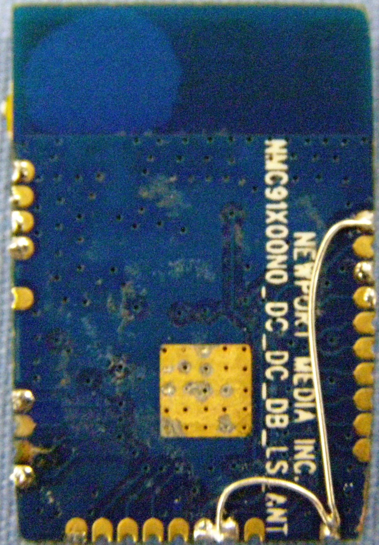
VW4ATWINC1500
Nov 17, 2014Wireless Module
Equipment Class
DTS - Digital Transmission System