VW4A091786RCB256RFR2 Module
Microchip Technology Inc.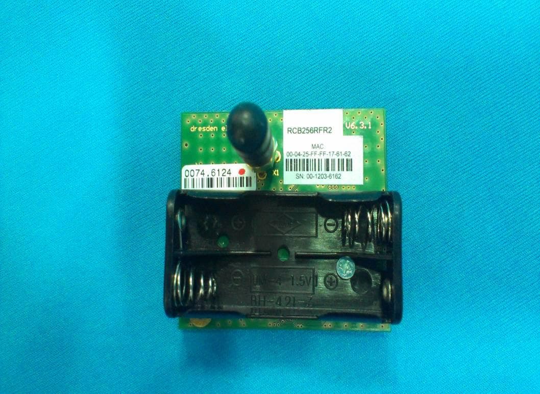
Click to zoom
Application Details
- Equipment Class
- DTS - Digital Transmission System
- Date of Grant
- Dec 26, 2012
- Application Purpose
- Original Equipment
- Date of Application
- Dec 22, 2012
- Equipment Note
- RCB256RFR2 Module
- Frequency Range
- 2405.00000000 - 2480.00000000
- Company
- Microchip Technology Inc.
- Country
- United States
Documents & Files
Document Text
Text extracted from the exhibit documents filed with the FCC. Open a document above to read the original.
Users Manual
APPLICATION NOTE Atmel AVR10003: ATmega256RFR2 Evaluation Kit – Quick Start Guide 8-bit Atmel Microcontrollers Features This application note briefly describes how to set up and run the pre-flashed performance test application included with the Atmel ® ATmega256RFR2. The latest dedicated applications can be downloaded from www.atmel.com and flashed to the kit hardware by using the serial bootloader functionality of the pre- flashed application. Kit contents 2x Atmel RCB256RFR2 Radio Controller Board 1x Atmel RCB Sensor Terminal Board (STB) 1x Atmel RCB Key Remote Control board 1x RCB-BB RS232 cable 1x USB cable 2x 2.4GHz antenna 4x AAA battery 1x Quick Start Guide 42033AVR09/2012 Atmel AVR10003: ATmega256RFR2 Evaluation Kit – Quick Start Guide [APPLICATION NOTE] 42033AVR09/2012 2 1. Simple range measurement The pre-flashed performance test application on the RCB256RFR2 radio controller boards features a simple range measurement. Each board operates in a standalone manner, and is able to transmit or receive data frames. A successful transmit or receive operation is indicated by a blinking LED. 1.1 Board assembling 1. Connect the antennas to both RCBs. 2. Insert two batteries in each of the RCBs. 1.2 Power up the boards Apply power to both RCBs by switching on the power switch located on the top side of the board. The RCBs run a power-on check and indicate the successful completion by switching on the second of the three LEDs. 1.3 Run simple range measurement application Choose one of the RCB256RFR2 RCBs, and press button T1 to start the simple range measurement application. First, the RCB initiates a connection and configuration procedure by sending broadcast frames, and waiting for a response from the second RCB. After a successful configuration, the RCBs turn on LED-D2 to indicate that status. Afterwards the initiator starts to transmit data frames immediately. Each data frame transmission is indicated by blinking the TX status LED-D3. A successful data frame reception on the second node is indicated by blinking the RX status LED-D4. The RX status LED stops blinking if no data frames are received, such as when, for example, the node has left the communication range. Data frame transmission can be stopped by pressing T1 once more on the node transmitting frames. Moreover the RCBs can transmit and receive frames simultaneously. Pressing button T1 on both nodes initiates each node to transmit frames. The three LEDs indicate their respective functions: LED-D2 a successful configuration, LED-D3 transmission and LED-D4 reception. Note: The node connection and configuration gets lost when the RCBs’ power supply is switched off. To restart the simple range measurement, power cycles both RCBs before pressing T1 on one RCB to restart the application. 2. Packet error rate measurement The pre-flashed performance test application is also configured with packet error rate (PER) measurement functionality (as defined in IEEE ® 802.15.4), enabling the user to explore various radio transceiver features, radio transceiver registers, and performance by tuning with customized configurations. For this application, one RCB256RFR2 RCB needs to be connected to a PC. config TX RX status D2 D3 D4 T1 Atmel AVR10003: ATmega256RFR2 Evaluation Kit – Quick Start Guide [APPLICATION NOTE] 42033AVR09/2012 3 2.1 Board assembling 1. Switch off power drom one RCB, or remove the batteries and connect the RCB to the STB. 2. Download the patched FT245RL driver files from the kit website, and follow the installation guidelines on your PC to install the USB driver. 3. Connect the STB to a PC with the USB cable. 4. A successful installation and enumeration of the USB connection with the PC is indicated by the power status LED on the STB. 2.2 Set up the terminal program on the PC A terminal program running on the PC is used to control the application running on the RCB connected to the STB. Set up the terminal program as follows: BAUD RATE: 9600 PARITY: None DATA BITS: 8 STOP BITS: 1 FLOW CONTROL: Off 2.3 Power up the boards 1. Apply the standalone RCB (optional) by turning on the power switch on the top side of the board. The RCB runs a power-on check and indicates the successful completion by switching on the second of the three LEDs. 2. The RCB mounted on the STB is powered via the USB connection. Make sure that the batteries are removed or that the power switch is in the off position. 2.4 Run the packet error rate measurement Type any character in the terminal window to initiate the configure procedure for both RCB nodes and show the menu. Optionally, if no peer node is active, the search for a peer device can be aborted by pressing ENTER. The node gets configured for stand-alone operation. The packet error rate measurement can be operated through the menu options displayed on the UART terminal program. A detailed description of the menu options can be found in the ATmega256RFR2 Evaluation Kit – User Guide. 3. Serial bootloader The application offers serial bootloader functionality to flash other applications to the RCBs. A detailed description on the usage of the bootloader can be found in the Atmel AVR2054 Serial Bootloader - User Guide. Atmel AVR10003: ATmega256RFR2 Evaluation Kit – Quick Start Guide [APPLICATION NOTE] 42033AVR09/2012 4 4. Agency Certification 4.1 UNITED STATES (FCC) This equipment complies with Part 15 of the FCC rules and regulations. To fulfill FCC Certification requirements, an OEM manufacturer must comply with the following regulations: 1. The RCB256RFR2 limited modular transmitter must be labeled with its own FCC ID number, and, if the FCC ID is not visible when the module is installed inside another device, then the outside of the device into which the module is installed must also display a label referring to the enclosed module. This exterior label can use wording such as the following: Contains FCC ID: VW4A091786 The enclosed device complies with Part 15 of the FCC Rules. Operation is subj…
Text truncated - open the document above for the full version.
Block Diagram
Atmel Norway AS Vestre Rosten 79, 7075 Tiller, Norway Tlf:+47 72 88 43 88 Fax +47 72 88 43 99 10.Oct.12 To whomsoever it may concern Product Block diagram This document features the internal block diagram of the product mentioned below. Product name: RCB256RFR2 Product Model: RCB256RFR2 FCC ID: VW4A091786 Product Block diagram: ATmega256RFR2Balun RFP RFN EEPROM C O N N E C T O R 1 C O N N E C T O R 2 Xtal 32KHz Xtal 16MHz JTAG ISP PE[7..0] (GPIO) PD[7..0] (GPIO) PF[7..0] (GPIO) +3.3V (EXT / BAT) SMA Internal Block diagram of ATmega256RFR2 RF Transceiver IC, showing Internal Voltage Regulator – AVREG, DVREG Atmel Norway AS Vestre Rosten 79, 7075 Tiller, Norway Tlf:+47 72 88 43 88 Fax +47 72 88 43 99 Sincerely, Saravanakumar Marudhachalam Manager, Tools HW Development, Atmel Norway AS
Cover Letter(s)
Atmel Norway AS Vestre Rosten 79, 7075 Tiller, Norway Tlf:+47 72 88 43 88 Fax +47 72 88 43 99 Applicant/Grantee Atmel Norway AS FCC ID: VW4A091786 Section 15.212 Modular Transmitters Request for Single Modular Approval Request for Limited Single Modular approval SI. No Requirements EUT Conditions Comply (Y/N) 01 The radio elements of the modular transmitter must have their own Shielding. The physical crystal and tuning capacitors may be located external to the shielded radio elements The Module has its own shielding. Shielding can be employed on the board structure. Y 02 The modular transmitter must have buffered modulation/data inputs (if such inputs are provided) to ensure that the module will comply with Part 15 requirements under conditions of excessive data rates or over-modulation All Modulation and data input(s) are buffered. Refer block diagram and schematic diagram. Y 03 The modular transmitter must have its Own power supply regulation. The ATmega256RFR2 transceiver has internal regulator as shown in the internal block diagram. Refer the Block diagram Y 04 The modular transmitter must comply with the antenna and transmission system requirements of Sections 15.203, 15.204(b) and 15.204(c). The antenna must either be permanently attached or employ a “unique” antenna coupler (at all connections between the module and The antenna, including the cable). The “professional installation” provision of Section 15.203 is not applicable to modules but can apply to limited Modular approvals under paragraph (b) of this section. The product has a standard SMA connector. N 05 The modular transmitter must be tested in a stand-alone configuration, i.e., the module must not be inside another device during testing for compliance With Part 15 requirements. Unless the transmitter module will be battery powered, it must comply with the AC line conducted requirements found in Section 15.207. AC or DC power lines and data input/output lines connected to the module must not contain ferrites, Y Atmel Norway AS Vestre Rosten 79, 7075 Tiller, Norway Tlf:+47 72 88 43 88 Fax +47 72 88 43 99 unless they will be marketed with the Module (see Section 15.27(a)). The length of these lines shall be the length typical of actual use or, if that length is unknown, at least 10 centimeters to insure that there is no coupling between the case of the module and supporting Equipment. Any accessories, peripherals, or support equipment connected to the module during testing shall be Unmodified and commercially available (see Section 15.31(i)). 06 The modular transmitter must be equipped with either a permanently affixed label or must be capable of electronically displaying its FCC Identification number. (A) If using a permanently affixed label, the modular transmitter must be labeled with its own FCC identification number, and, if the FCC identification number is not visible when the module is installed inside another device, then the outside of the device into which the module is Installed must also display a label referring to The enclosed module. This exterior label can use wording such as the following: “Contains Transmitter Module FCC ID: XYZMODEL1” or “Contains FCC ID: XYZMODEL1.” Any similar wording That expresses the same meaning may be used. The Grantee may either provide such a label, an example of which must be included in the application for equipment authorization, or, must provide adequate Instructions along with the module which explain This requirement. In the latter case, a copy of these instructions must be included in the Application for equipment authorization. (B) If the modular transmitter uses an electronic display of the FCC identification number, the information must be readily accessible and visible on the modular transmitter or on the Device in which it is installed. If the module is installed inside another device, then the Refer AVR10003 document. Section 4. Y Atmel Norway AS Vestre Rosten 79, 7075 Tiller, Norway Tlf:+47 72 88 43 88 Fax +47 72 88 43 99 outside of the device into which the module is installed must display a label referring to the enclosed Module. This exterior label can use wording such as the following: “Contains FCC certified transmitter module(s).” Any similar wording that expresses the same Meaning may be used. The user manual must include instructions on how to access the Electronic display. A copy of these instructions Must be included in the application for equipment authorization. 07 The modular transmitter must comply with any specific rules or operating requirements that ordinarily apply to a complete transmitter and the manufacturer must provide adequate instructions along with the module to explain any such Requirements. A copy of these Instructions must be included in the application for equipment authorization. . Refer AVR10003 document. Y 08 The modular transmitter must comply with any applicable RF exposure requirements in its final configuration Y A limited modular approval may be granted for single or split modular transmitters that do not comply with all of the above requirements, e.g., shielding, minimum signaling amplitude, buffered modulation/data inputs, or power supply regulation, if the manufacturer can demonstrate by alternative means in the application for equipment authorization that the modular transmitter meets all the applicable Part 15 requirements under the operating conditions in which the transmitter will be used. Limited modular approval also may be granted in those instances where compliance with RF exposure rules is demonstrated only for particular product configurations. The applicant for certification must state how control of the end product into which the module will be installed will be maintained such that full compliance of the end product is always ensured Sincerely, Saravanakumar Marudhachalam Manager, Tools HW development
External Photos
www.tuv.com Appendix 2 Prüfbericht - Nr.: Test Report No. 01200121 001 Seite 1 von 3 Page 1 of 3 EUT Side View EUT Top View www.tuv.com Appendix 2 Prüfbericht - Nr.: Test Report No. 01200121 001 Seite 2 von 3 Page 2 of 3 EUT Bottom View EUT Dimensional View www.tuv.com Appendix 2 Prüfbericht - Nr.: Test Report No. 01200121 001 Seite 3 von 3 Page 3 of 3 EUT Dimensional View Antenna Dimensional View
ID Label/Location Info
www.tuv.com Appendix 4 Prüfbericht - Nr.: Test Report No. 01200121 001 Seite 1 von 1 Page 1 of 1 Label Diagram Label Location
Internal Photos
www.tuv.com Appendix 3 Prüfbericht - Nr.: Test Report No. 01200121 001 Seite 1 von 3 Page 1 of 3 Inner View of Enclosure Top View of Enclosure www.tuv.com Appendix 3 Prüfbericht - Nr.: Test Report No. 01200121 001 Seite 2 von 3 Page 2 of 3 RF Module with Shield Opened RF Module with Shield Opened – Top View www.tuv.com Appendix 3 Prüfbericht - Nr.: Test Report No. 01200121 001 Seite 3 von 3 Page 3 of 3 RF Module – Bottom View as marked ( Removed Battery holder)
Operational Description
Atmel Norway AS Vestre Rosten 79, 7075 Tiller, Norway Tlf:+47 72 88 43 88 Fax +47 72 88 43 99 05.Dec.12 Theory of Operation/Technical Description – FCC ID: VW4A091786 - RF circuit function: The IEEE 802.15.4 compliant transceiver inside the Atmega256RFR2 SoC generates a modulated carrier wave at 2.4000- 2.4835 GHz with 16 IEEE 802.15.4 channels. This transceiver circuit is used by system applications as a physical layer for ZigBee applications. - RF signal flow: The Transceiver IC outputs a differential RF signal- RFP & RFN which then passes through the RF path till the antenna and gets radiated or vice versa during reception - Description of Antenna system: The Balun in the RF path converts the differential RF signal into a single ended 50 ohm side where it is fed to the Antenna connector after passing through tuning elements present to ensure compliance. - Compliance with 15.203 antenna requirements: FCC 15.203 requirements for this design are tested and verified during FCC compliance testing. - Description of all modulation schemes used in the product: Module uses O-QPSK with half-sine pulse shaping. Saravanakumar Marudhachalam Manager, Tools HW Development
Operational Description
Tekfun Co., Ltd. ________________________________________________________________________________________________________________________________________________________________________________________________________________________________ ___ TEKFUN CO., Ltd. E-mail: [email protected] URL: www.tekfun.com.tw 4F., No.32, Kunming St., Jhongli City, Taoyuan Hsien 32089, Taiwan Tel : 886-3-4280826 Fax:886-3-4280010 SPECIFICATION FOR APPROVAL CUSTOMER DESCRIPTION 2.4GHz Rubber Stubby Antenna with SMA Male Straight PART NO. M01-SS2 DATE DESIGNER DIRECTOR Approved by Customer/date: Tekfun Co., Ltd. Page1 of 6 ________________________________________________________________________________________________________________________________________________________________________________________________________________________________ ___ TEKFUN CO., Ltd. E-mail: [email protected] URL: www.tekfun.com.tw 4F., No.32, Kunming St., Jhongli City, Taoyuan Hsien 32089, Taiwan Tel : 886-3-4280826 Fax:886-3-4280010 ANTENNA SPECIFICATIONS FOR APPROVAL 1. GENERAL DESCRIPION 1.1 Type No. : M01-SS2 1.2 Customer P/N : 2. DESCRIPTION & APPLICATION 2.4GHz Rubber Stubby Antenna with SMA Male Straight 3. ELECTRICAL CHARACTERISTICS 3.1 Frequency Range : 2.4GHz (2.4~2.5GHz) 3.2 Electric Wave : 1/4, Monopole Antenna 3.3 V.S.W.R : < 2 3.4 Impedance : 50 Ω, Nominal 3.5 Gain : < 0dBi 3.6 Connector : SMA Male Straight 4. PACKING STYLE Poly Bag Tekfun Co., Ltd. ________________________________________________________________________________________________________________________________________________________________________________________________________________________________ ___ TEKFUN CO., Ltd. E-mail: [email protected] URL: www.tekfun.com.tw 4F., No.32, Kunming St., Jhongli City, Taoyuan Hsien 32089, Taiwan Tel : 886-3-4280826 Fax:886-3-4280010 5. APPEARANCE DRAWING Tekfun Co., Ltd. ________________________________________________________________________________________________________________________________________________________________________________________________________________________________ ___ TEKFUN CO., Ltd. E-mail: [email protected] URL: www.tekfun.com.tw 4F., No.32, Kunming St., Jhongli City, Taoyuan Hsien 32089, Taiwan Tel : 886-3-4280826 Fax:886-3-4280010 6. Test Report VSWR Tekfun Co., Ltd. ________________________________________________________________________________________________________________________________________________________________________________________________________________________________ ___ TEKFUN CO., Ltd. E-mail: [email protected] URL: www.tekfun.com.tw 4F., No.32, Kunming St., Jhongli City, Taoyuan Hsien 32089, Taiwan Tel : 886-3-4280826 Fax:886-3-4280010 7. Test Report Return LOSS
Operational Description
www.tuv.com Appendix 6 Prüfbericht - Nr.: Test Report No. 01200121 001 Seite 1 von 1 Page 1 of 1 Specifications of EUT Operating Frequency 2400MHz – 2483.5MHz No. of channels 16 Channel Spacing 5MHz Modulation DSSS ( O-QPSK ) Transmitted Power 5.07 dBm Data Rate 250 kbps Antenna Type External Antenna Number of antenna 1 Antenna Gain 0 dBi Supply Voltage 1.8V – 3.6V Dimensions Length: 52mm Width: 45mm Environmental -25 to +85 degrees C; Storage: -45 to +125 degrees C
Operational Description
Atmel Norway AS Vestre Rosten 79, 7075 Tiller, Norway Tlf:+47 72 88 43 88 Fax +47 72 88 43 99 10 th Oct 2012 To whomsoever it may concern Product Application This document explains the nature of intended application of the product mentioned below. Product name: RCB256RFR2 Module Product Model: RCB256RFR2 FCC ID: VW4A091786 Product Application: The RCB256RFR2 is a reference design for the Atmel ATmega256RFR2 single-chip microcontroller and radio transceiver. The IC integrates a powerful, 8-bit AVR ® RISC microcontroller, an IEEE 802.15.4-compliant transceiver, and additional peripheral features. The built-in radio transceiver supports the worldwide accessible 2.4GHz ISM band. The system is designed to demonstrate standard-based applications such as ZigBee/IEEE 802.15.4, ZigBee RF4CE, and 6LoWPAN, as well as high data rate ISM applications. The SMA antenna connector allows either operation with the antenna provided with the RCB or conducting RF performance measurements. Sincerely, Saravanakumar Marudhachalam Manager, Tools HW Development, Atmel Norway AS
Parts List/Tune Up Info
RCB256RFR2 Bill of Material Qty Component Name Location Description Manufacturing Part Number Manufacturer 1 A09-1786 RCB256RFR2 PCBA 9 A01-0352 C11, C12, C13, C14, C15, C18, C19, C8, C9 Ceramic capacitor, SMD 0402, X7R, 16V, +/-10% (de19761), 100nF GRM155R71C104KA88D Murata 2 A01-0353 C4, C7 Ceramic capacitor, SMD 0603, X5R, 16V, 10% (de19763), 1uF GRM188R61C105KA12D Murata 3 A01-0354 C1, C3, C5 Ceramic capacitor, SMD 0402, NP0, 50V, +/-5% (de19768), 22pF CM05CG220J50AH Kyocera-elco 2 A01-0356 C10, C6 Ceramic capacitor, SMD 0402, NP0, 50V, +/-5% (de16674), 10pF ECJ0EC1H100D Panasonic 1 A01-0361 C16 SMD tantalum capacitor 6032 (de8897), 47uF/10V TAJC476M010 AVX 1 A01-0362 C2 Ceramic capacitor, SMD 0402, X7R, 25V, 10 %, (de16677), 10nF C1005X7R1E103K tdk 4 A02-0559 R10, R5, R6, R7 Thick film resistor, SMD 0402, 1/16W, 1% (de19764), 470R RC1005F 4700CS Samsung 4 A02-0567 R1, R3, R8, R9 Thick film resistor, SMD 0402, 1/16W, 1% (de13875), 10k0 RC1005F1002CS Samsung 1 A02-0568 R4 Thick film resistor, SMD 0402, 1/16W, 1% (de20048), 0R00 RC1005J000CS Samsung 1 A03-0074 L1 SMD-Ferrite 1000Ohm, 100MHz 0603 size, (de19760), 1000ohm@100MHz 74279266 Würth Elektronik 1 A03-0075 B1 2,4GHz FilterBalun, SMD 1.25x2.0mm (de26949), 2450FB15L0001E 2450FB15L0001E Johanson Technology 1 A06-0583 U2 1kbit Serial EEPROM, AT25010B-MAHL-T, 1.8-5V, Ultra Thin UDFN-8 (de30551), AT25010B-MAHL-T AT25010B-MAHL-T ATMEL 1 A06-0793 U3 AVR Microcontroller with Low Power 2.4GHz Transceiver for IEEE 802.15.4 (de35289) , ATMEGA256RFR2-ZU ATMEGA256RFR2-ZU ATMEL 1 A07-0054 Q2 16MHz SX-4025, 4 x 2.5 mm SMD 10ppm (de19513), 16MHz XTL551150NLE-16.0MHz-9.0R SIWARD 1 A07-0056 Q1 32.768kHz KX-327NHT, 3.2 x 1.5 mm SMD 20ppm (de19774), 32.768kHz 12.8715 GEYER ELECTRONIC 1 A08-0941 Batt1 PCB battery Holder for 2x AAA cells THM (de20365), BH421-3P BH421-3P Comfortable Electronic Co.Ltd. 1 A08-0947 SW1 Slide Switch, right angle 3 pol, 2 pos, (de20049), SPDT 09.10201.02 EAO 1 A08-0949 NUT1 Nut M2.5 DIN standard 934 (de4521), Nut M2.5 1 A08-0950 SCR1 Screw M2.5x8 DIN standard 965 (de5252), 0048 25 8 0048 25 8 Würth Elektronik 1 A08-0959 PCB RCB128RFA1 V6.3.1 PCB, RCB128RFA1 PCB 5 449 27 00.251.01 G&W Leiterplatten Dresden GmbH 1 A08-0960 SH1 EMI Shield Frame 25x30x3mm (de26517), LT08AD4303F LT08AD4303F Laird Technologies 1 A08-0961 SH1 EMI Shield Cover 25.6x30.6x2mm (de28985), LT08AD4303C LT08AD4303C Laird Technologies 1 A08-0961 SH1 EMI Shield Cover 25.6x30.6x2mm (de28985), LT08AD4303C LT08AD4303C Laird Technologies 1 A08-0962 T1 Tactile Switches, KSR 3,8x6mm,SMD (de19759), KSR211GLFS KSR211GLFS ITT cannon 1 A08-0963 X1 SMA PCB mounted connector 50Ohm (de19205), 19-46-1-TGG 19-46-1-TGG Multicomp 2 A08-0964 EXT0, EXT1 Socket 2x15, SMD, 1.27mm Pitch (de19765), SFM-115-L2-S-D-LC SFM-115-L2-S-D-LC SAMTEC 2 A08-0993 Plug1, Plug2 Miniature Spring Socket Assembly (de21786), 2-331677-2 2-331677-2 TYCO 1 A08-1012 LAB2 Label with TELEC Logo, part name and TELEC ID, Label TELEC 1 A09-0847 LAB1 Label for use on wireless PCBA that needs 64 bit MAC and FCC ID , Label PCBA with MAC64 and FCC ID 505462 ACT Logimark AS 4 A10-0065 D2, D3, D4, D5 LED, Red, Wave length=628nm, SMD 0603 (de19773), TLMS1000-GS08 TLMS1000-GS08 vishay 1 A11-0059 SOFT1 REB/RCB Test software, REB/RCB Test software 1 A12-0330 Docu RCB128RFA1_V6.3.1, RCB128RFA1_V6.3.1 PCBA Documents dresden elektronik
RF Exposure Info
www.tuv.com Appendix 10 Prüfbericht - Nr.: Test Report No. 01200121 001 Seite 1 von 1 Page 1 of 1 Radio Frequency Human Exposure Evaluation: The highest RF output power of the EUT at 2405 MHz was measured 5.07dBm (3.213mW) which is less than 20mW. Since maximum peak output power of the transmitter is <60/f (GHz) mW, i.e. 3.213mW<24.94(=60/2.405) mW, hence the EUT is excluded from SAR evaluation according to FCC KDB publication 447498 D01: Mobile Portable RF Exposure.
Schematics
1 1 2 2 3 3 4 4 5 5 6 6 7 7 8 8 DD CC BB AA A09-1264_REV4 A09-1264-SCHEMATICS.SchDoc 1105-Dec-121:13:19 PM * ATMEL India RMZ MILLENIA-2 MGR ROAD PERUNGUDI CHENNAI INDIA PAGE:of TITLE: Document number:Revision:A Date: * * C12 100n C19 100n C3 22p C5 22p R1 10k 12 34 56 78 910 1112 1314 1516 1718 1920 2122 2324 2526 2728 2930 EXT1 SFM-115-L2-S-D-LC 12 34 56 78 910 1112 1314 1516 1718 1920 2122 2324 2526 2728 2930 EXT0 SFM-115-L2-S-D-LC D2 rot D3 rot D4 rot T1 ITT KSR211GLFS R7 470 R6 470 R5 470 Batt1 AAAx2 L1 Wuerth74279266 SW1 Eao09.10201.02 (32kHz) C2 10n Q1 CFPX-157 Plug1 AMP 2-331677-2 A 2 K 1 D1 n.i. C4 1uF 1 3 2 4 Q2 16MHz / CL=10pF C10 10p C6 10p RFNRFP DGND DGND DGND DGND C7 1uF DGND DGND PE0 PE1 PE2 PE3 PE6 PE7 PF0 PF1 PF2 PF3 PF4 PF5 PF6 PF7 V_RCB RSTN DGND PB0 PB1 PB2 PB3 PB4 PB5 PB6 PB7 PD0 PD1 PD2 PD3 PD4 PD5 PD6 PD7 C18 100n C9 100n PG3 PG4 PG5 DGNDDGND DGND V_RCB DGND V_RCBV_RCB Plug2 AMP 2-331677-2 DGND V_RCB DGND DGND DGND DGND DGND PB1 PD0PD1 PD2PD3 PD4PD5 PD6PD7 PE0PE1 PE2PE3 PE6PE7 PF0PF1 PF2PF3 PF4PF5 PF6PF7 DGNDDGNDDGND V_RCB AREF V_RCB PB0PB1 PB2PB3 PB4PB5 PB6PB7 AREF RSTN DGND DGND MetalMount 1 M1 Mounting Hole DGND DGND C13 100n C14 100n C15 100n DGND V_RCB u n b a l a n c e d 1 D C _ G N D 2 B a l a n c e d P 1 3 B a l a n c e d P 2 4 G N D 5 nc 6 Johanson 2450FB15L0001E Alternativ: Würth 748421245; de19256 B1 Balun+Filter_SMD DGNDDGND DGNDDGND CLKI CLKI PD4PD5 PD6PD7 ALE ALE #WR#RD #CS 1 SO 2 #WP 3 GND 4 SI 5 SCK 6 #HOLD 7 VCC 8 AT25010A U2 AT25010A R3 10kC11 100n #WR #RD PE4 PE5 TST TST PB1 PB2 PB3 Configure PB0:SSN as OUT when accessing the board information EEPROM DGND DGND PG5 R4 0 R2 n.i. V_RCBV_RCBV_RCB PG0 PG1 PG0PG1 RSTON RSTON 1 SH1 Shield_BMIS DGND C8 100n 1 2 . 1 2 . 2 2 . 3 2 . 4 X1 SMA Vertical DGNDDGND DGNDDGND C1 22p R8 10k R9 10k DGNDDGND C L K I T S T R10 470 D5 rot RSTON DGND RF1 REF1TOP RF2 REF2TOP ATMEGA256RFR2-ZU PF2:ADC2:DIG2 1 PF3:ADC3:DIG4 2 PF4:ADC4:TCK 3 PF5:ADC5:TMS 4 PF6:ADC6:TDO 5 PF7:ADC7:TDI 6 PF1:ADC1 64 PF0:ADC0 63 PB0:SSN:PCINT0 36 PB1:SCK:PCINT1 37 PB2:MOSI:PDI:PCINT2 38 PB3:MISO:PDO:PCINT3 39 PB4:OC2A:PCINT4 40 PB5:OC1A:PCINT5 41 PB6:OC1B:PCINT6 42 PB7:OC0A:OC1C:PCINT7 43 PD0:SCL:INT0 25 PD1:SDA:INT1 26 PD2:RXD1:INT2 27 PD3:TXD1:INT3 28 PD4:ICP1 29 PD5:XCK1 30 PD6:T1 31 PD7:T0 32 PE0:RXD0:PCINT8 46 PE1:TXD0 47 PE2:XCK0:AIN0 48 PE3:OC3A:AIN1 49 PE4:OC3B:INT4 50 PE5:OC3C:INT5 51 PE6:T3:INT6 52 PE7:ICP3:INT7:CLKO 53 PG0:DIG3 14 PG1:DIG1 15 PG2 / AMR 16 PG3:TOSC2 17 PG4:TOSC1 18 PG5:OC0B 19 DEVDD 23 DEVDD 34 DEVDD 44 DEVDD 54 DVSS 24 DVSS 35 DVSS 45 DVSS 55 A V S S _ R F P 7 R F P 8 R F N 9 A V S S _ R F N 1 0 AVSS:ASVSS 58 AVSS 61 EVDD 59 AVDD 60 DVDD 21 DVDD 22 DVSS:DSVSS 20 XTAL2 56 XTAL1 57 AREF 62 CLKI 33 Paddle 65 TST 11 RSTN 12 RSTON 13 U3 47uF/10V C16 RCB256RFR2 MODULE FCC ID: VW4A091786 Backward Compatibility RCB2xx| Pin| RCB128RFA1 ------------------------------------------------------------ PA0EXT1.23PB0 PA1EXT1.24PB1 PA2EXT1.25PB2 PA3EXT1.26PB3 PA4EXT1.27PB4 PA5EXT1.28PB5 PA6EXT1.29PB6 PA7EXT1.30PB7 PE4EXT1.6RSTON PE5EXT1.5TST Backward Compatibility RCB2xx| Pin| RCB128RFA1 ------------------------------------------------------------ PC4EXT0.25PD4 PC5EXT0.26PD5 PC6EXT0.27PD6 PC7EXT0.28PD7 PG0EXT0.17PE4 PG1EXT0.18PE5 PB6EXT0.1PG0 PB7EXT0.2PG1 XTAL1EXT0.7CLKI
Schematics
PAB102 PAB106 PAB105 PAB104PAB103 PAB101 COB1 PABatt103 PABatt101 PABatt102 COBatt1 PAC101PAC102 COC1 PAC202PAC201 COC2 PAC302 PAC301 COC3 PAC401 PAC402 COC4 PAC502 PAC501 COC5 PAC602 PAC601 COC6 PAC702 PAC701 COC7 PAC801 PAC802 COC8 PAC902PAC901 COC9 PAC1002 PAC1001 COC10 PAC1102PAC1101 COC11 PAC1202 PAC1201 COC12 PAC1302 PAC1301 COC13 PAC1402PAC1401 COC14 PAC1502 PAC1501 COC15 PAC1602PAC1601 COC16 PAC1802 PAC1801 COC18 PAC1902PAC1901 COC19 PAD102PAD101 COD1 PAD20A PAD20K COD2 PAD30K PAD30A COD3 PAD40K PAD40A COD4 PAD50K PAD50A COD5 PAEXT002PAEXT004PAEXT006PAEXT008PAEXT0010PAEXT0012PAEXT0014PAEXT0016PAEXT0018PAEXT0020PAEXT0022PAEXT0024PAEXT0026PAEXT0028PAEXT0030 PAEXT001PAEXT003PAEXT005PAEXT007PAEXT009PAEXT0011PAEXT0013PAEXT0015PAEXT0017PAEXT0019PAEXT0021PAEXT0023PAEXT0025PAEXT0027PAEXT0029 PAEXT000 COEXT0 PAEXT102PAEXT104PAEXT106PAEXT108PAEXT1010PAEXT1012PAEXT1014PAEXT1016PAEXT1018PAEXT1020PAEXT1022PAEXT1024PAEXT1026PAEXT1028PAEXT1030 PAEXT101PAEXT103PAEXT105PAEXT107PAEXT109PAEXT1011PAEXT1013PAEXT1015PAEXT1017PAEXT1019PAEXT1021PAEXT1023PAEXT1025PAEXT1027PAEXT1029 PAEXT100 COEXT1 PAL101 PAL102 COL1 PAM101 COM1 PAQ102 PAQ101 COQ1 PAQ204 PAQ203PAQ202 PAQ201 COQ2 PAR102PAR101 COR1 PAR201 PAR202 COR2 PAR301 PAR302 COR3 PAR401PAR402 COR4 PAR501 PAR502 COR5 PAR602 PAR601 COR6 PAR702 PAR701 COR7 PAR802 PAR801 COR8 PAR902 PAR901 COR9 PAR1001 PAR1002 COR10 CORF1 CORF2 PASH101 COSH1 PASW101 PASW103 PASW102 COSW1 PAT102 PAT101 COT1 PAU208 PAU207 PAU206 PAU205PAU204 PAU203 PAU202 PAU201 COU2 PAU3064 PAU307PAU304PAU305PAU306PAU308 PAU3063 PAU3042PAU3041PAU3040PAU3039PAU3038PAU3037PAU3036PAU3035PAU3034PAU3033 PAU3032 PAU3030 PAU3028 PAU3027 PAU3062 PAU3053 PAU3043 PAU3031 PAU3029 PAU3026 PAU3025 PAU3024 PAU3023 PAU3022 PAU3021 PAU3020 PAU3019 PAU3018 PAU3017 PAU3016PAU3015PAU3014PAU3013PAU3012PAU3011PAU3010PAU309PAU301 PAU3065 PAU3052 PAU302PAU303 PAU3061 PAU3060 PAU3058 PAU3057 PAU3056 PAU3055 PAU3054 PAU3051 PAU3050 PAU3049 PAU3048PAU3047PAU3046PAU3045PAU3044 PAU3059 COU3 PAX101PAX10201 PAX10202 PAX10203 PAX10204 COX1 PAEXT0018 PAT101 PAU3051 PAEXT0017 PAR502 PAU3050 PAEXT0030 PAU3016 PAEXT1012 PAU3062 PAEXT007 PAR802 PAU3033 PAB105 PAB106 PABatt102 PABatt103 PAC102 PAC201 PAC302 PAC402 PAC502 PAC602 PAC702 PAC802 PAC902 PAC1002 PAC1102 PAC1202 PAC1302 PAC1402 PAC1502 PAC1602 PAC1802 PAC1901 PAEXT005 PAEXT008 PAEXT0019 PAEXT0020 PAEXT0021 PAEXT0022 PAEXT0023 PAEXT0024 PAEXT0029 PAEXT102 PAEXT1011 PAEXT1022 PAM101 PAQ202 PAQ204 PAR801PAR901 PASH101 PAT102 PAU204 PAU307PAU3010 PAU3020 PAU3024 PAU3035PAU3045 PAU3055 PAU3058 PAU3061 PAU3065 PAX10201 PAX10202 PAX10203 PAX10204 PAB101 PAX101 PAB102PAC101 PABatt101 PASW101 PAC401 PAU3060 PAC601 PAQ203 PAU3057 PAC701 PAC901 PAU3021 PAU3022 PAC801 PAL101 PAU3059 PAC1001 PAQ201 PAU3056 PAD20K PAR701 PAD30K PAR601 PAD40K PAR501 PAD50K PAR1001 PAR202 PAR401 PAU201 PAR301 PAU203 PAEXT1023 PAU3036 PAEXT101 PAEXT1024 PAU206 PAU3037 PAEXT1025 PAU205 PAU3038 PAEXT1026 PAU202 PAU3039 PAEXT1027 PAU3040 PAEXT1028 PAU3041 PAEXT1029 PAU3042 PAEXT1030 PAU3043 PAEXT009 PAU3025 PAEXT0010 PAU3026 PAEXT0011 PAU3027 PAEXT0012 PAU3028 PAEXT0013PAEXT0025 PAU3029 PAEXT0014PAEXT0026 PAU3030 PAEXT0015PAEXT0027 PAU3031 PAEXT0016PAEXT0028 PAU3032 PAEXT1010 PAU3046 PAEXT109 PAU3047 PAEXT108 PAR702 PAU3048 PAEXT107 PAR602 PAU3049 PAEXT104 PAU3052 PAEXT103 PAU3053 PAEXT1013 PAU3063 PAEXT1014 PAU3064 PAEXT1015 PAU301 PAEXT1016 PAU302 PAEXT1017 PAU303 PAEXT1018 PAU304 PAEXT1019 PAU305 PAEXT1020 PAU306 PAEXT001 PAU3014 PAEXT002 PAU3015 PAC301 PAQ101 PAU3017 PAC501 PAQ102 PAU3018 PAR402 PAU3019 PAB103 PAU309 PAB104 PAU308 PAC202 PAD102 PAEXT003 PAR101 PAU3012 PAEXT106 PAR1002 PAU3013 PAEXT105 PAR902 PAU3011 PAC1101 PAC1201 PAC1301 PAC1401 PAC1501 PAC1601 PAC1801 PAC1902 PA…
Text truncated - open the document above for the full version.
Contact Information
Applicant
Steve Caldwell(Vice President, Wireless Solutions Group)
Test Firm
TUV Rheinland (India) Pvt. Ltd.,B GURUPRASAD
Technical Specifications
| # | Rule Parts | Frequency Range | Power Output |
|---|---|---|---|
| 1 | 15C | 2.40 GHz - 2.48 GHz | 3.21 mW |
Other Applications from Microchip Technology Inc.
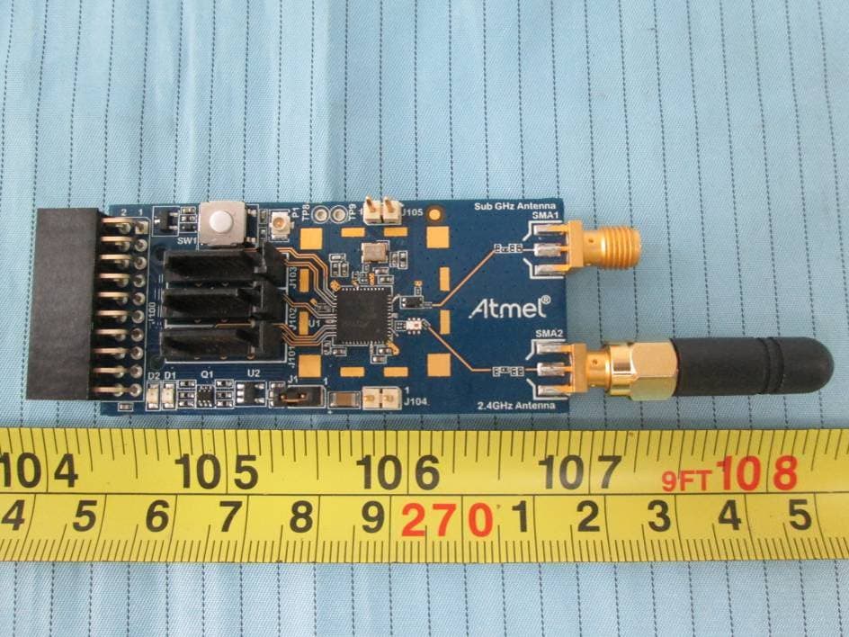
VW4A091980
Dec 22, 2015ATREB215-XPRO
Equipment Class
DXX - Part 15 Low Power Communication Device TransmitterVW4A092412
Mar 27, 2015ATSAMR21ZLL-EK
Equipment Class
DTS - Digital Transmission System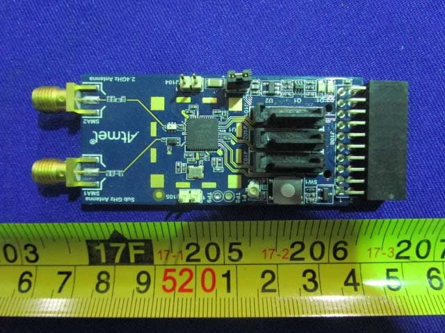
VW4A091982
Mar 21, 2015ATREB215-XPRO
Equipment Class
DTS - Digital Transmission System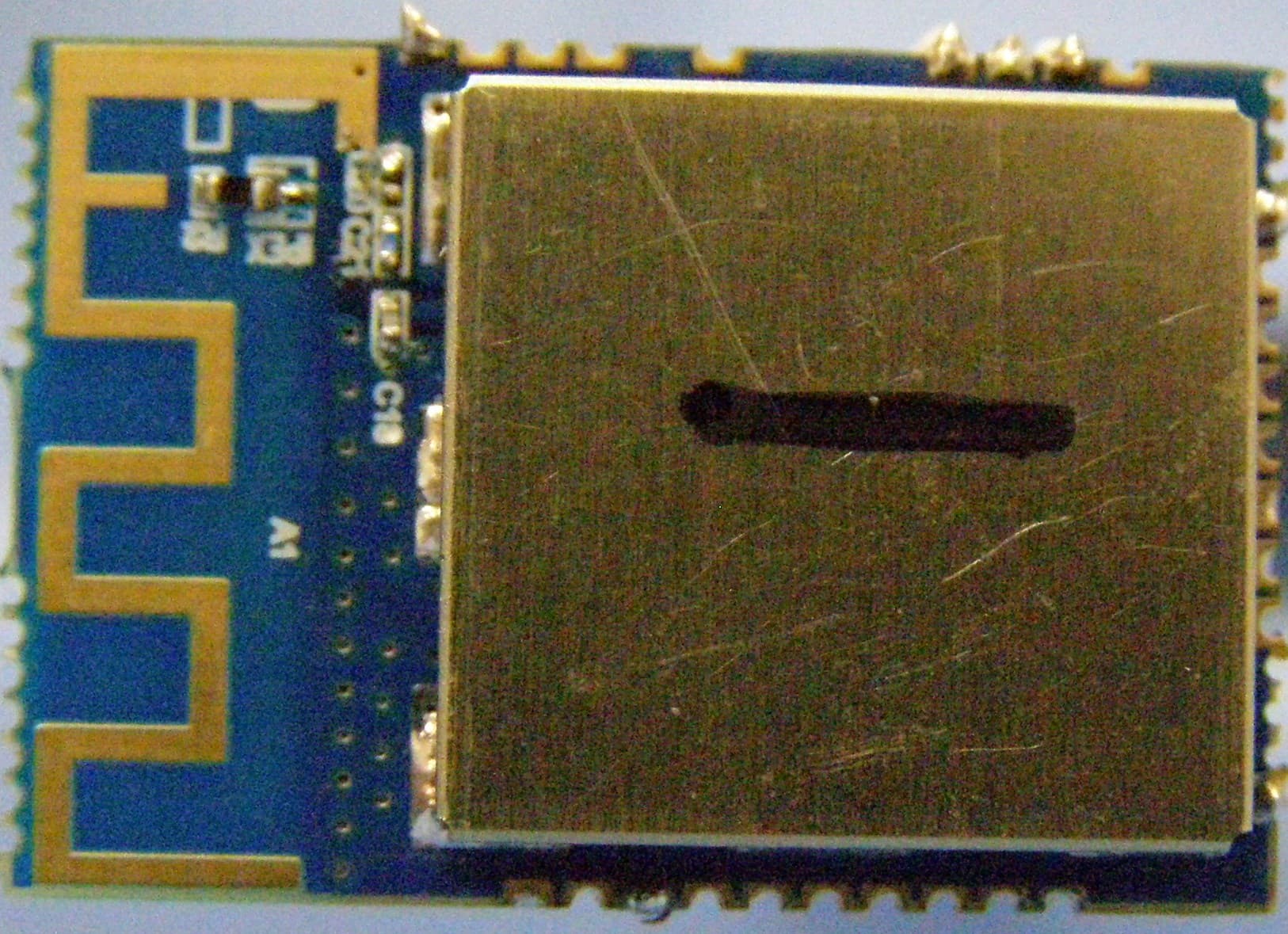
VW4ATWILC1000
Dec 03, 2014Wireless Module
Equipment Class
DTS - Digital Transmission System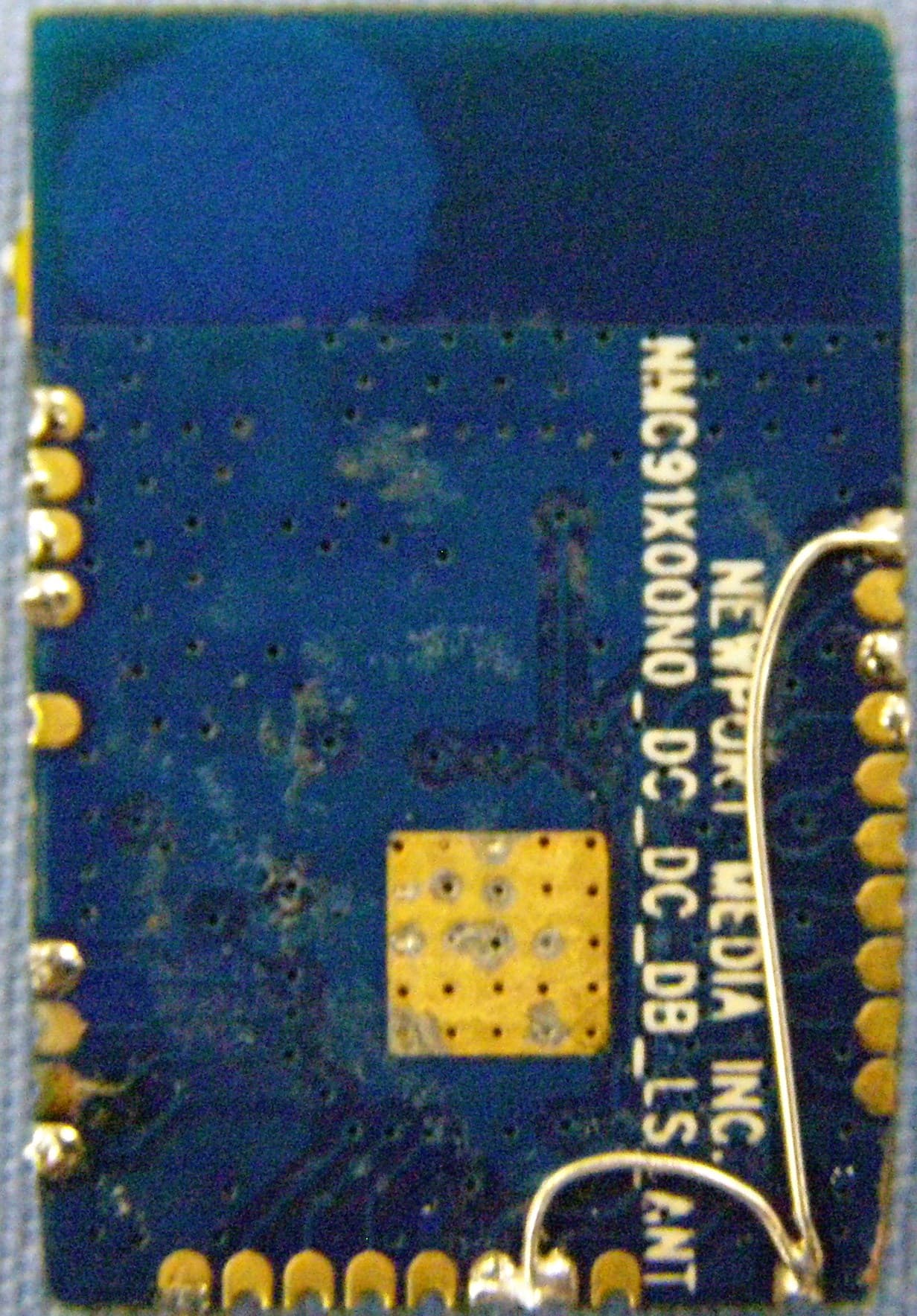
VW4ATWINC1500
Nov 17, 2014Wireless Module
Equipment Class
DTS - Digital Transmission System