VW4A092007ATRCB256RFR2-XPRO RCB256RF2 extension for XPRO
Microchip Technology Inc.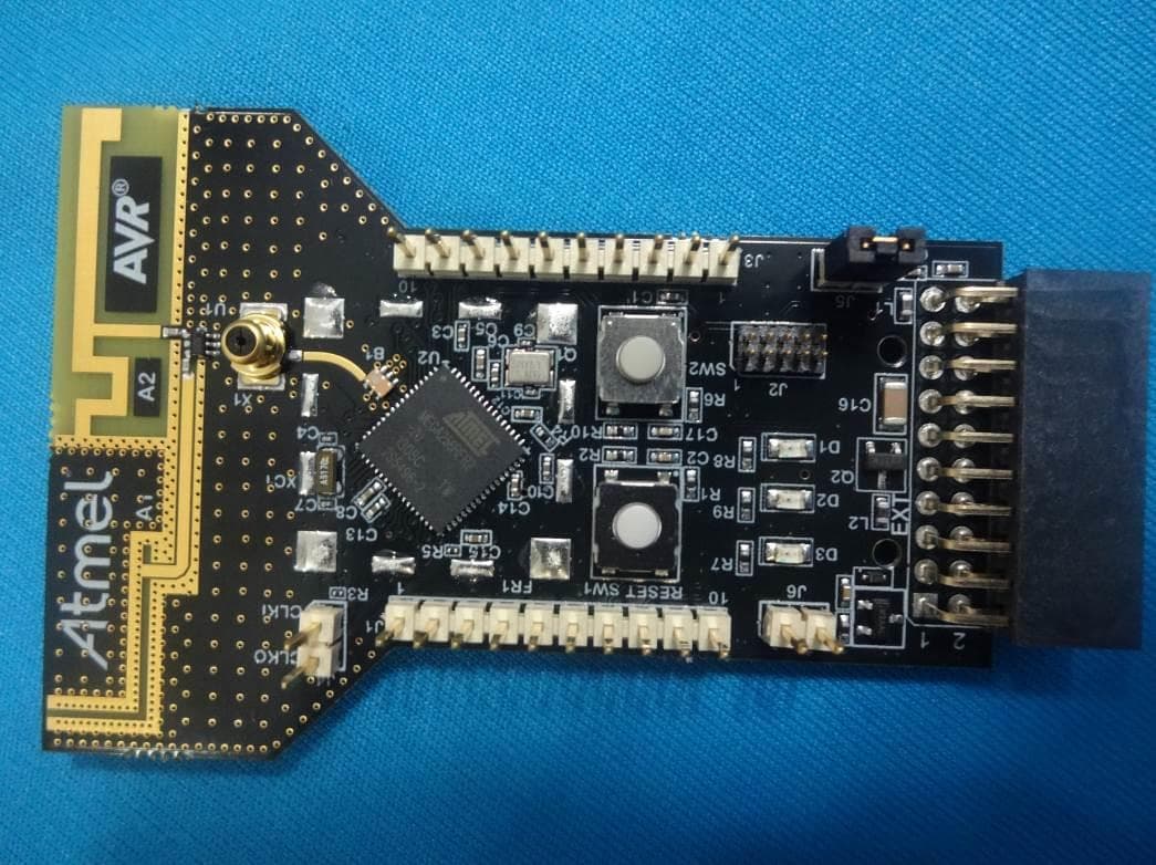
Click to zoom
Application Details
- Equipment Class
- DTS - Digital Transmission System
- Date of Grant
- Sep 29, 2013
- Application Purpose
- Original Equipment
- Date of Application
- Sep 26, 2013
- Equipment Note
- ATRCB256RFR2-XPRO RCB256RF2 extension for XPRO
- Frequency Range
- 2405.00000000 - 2480.00000000
- Company
- Microchip Technology Inc.
- Country
- United States
Documents & Files
Document Text
Text extracted from the exhibit documents filed with the FCC. Open a document above to read the original.
Users Manual
TBDA-MCU-09/2013 USER GUIDE AT04357 RCB256RFR2-XPRO User Guide Introduction This application note describes how to get started with the Atmel® RCB256RFR2-XPRO Extension board. The Extension boards is targeted for evaluating the features of the Atmel ATmega256RFR2 wireless SoC with PCB antenna. AT04357 RCB256RFR2-XPRO User Guide [USER GUIDE] TBDA-MCU-09/2013 2 Table of Contents Introduction .................................................................................... 1 1. Getting Started ........................................................................ 3 1.1.Features .............................................................................. 3 1.2.Design documentation and related links ..................................... 3 1.3.Board Assembly .................................................................... 3 1.3.1.Connect to a Xplained PRO board ............................... 3 1.3.2.Standalone node ....................................................... 3 1.3.3.In customer development assembly .............................. 3 1.4.Connecting the kit ................................................................. 3 1.4.1.Atmel Studio ............................................................ 4 1.4.2.Connect the extension UART to the EBDG COM port ....... 4 1.5.Programming ........................................................................ 4 1.5.1.JTAGICE ................................................................. 4 1.5.2.Boot loader .............................................................. 4 1.6.Available example code .......................................................... 5 2. Performance Analyzer ............................................................. 6 2.1.Introduction .......................................................................... 6 2.2.Program installation ............................................................... 6 2.3.Program use ........................................................................ 9 3. Xplained Pro .......................................................................... 11 3.1.Hardware identification system ............................................... 11 3.2.Standard headers and connectors .......................................... 11 3.2.1.Xplained Pro standard extension header ...................... 11 4. Hardware user guide ............................................................ 13 4.1.Board overview ................................................................... 13 4.2.Headers and connectors ....................................................... 13 4.2.1.J100 Xplained Pro extension connector ....................... 13 4.2.2.J1 & J3 ................................................................. 14 4.2.3.JTAG (J2) .............................................................. 14 4.2.4.CLK (J4) ................................................................ 15 4.2.5.Current monitoring (J5) ............................................. 15 4.2.6.External power (J6) ................................................. 15 4.3.Board GUI .......................................................................... 16 4.3.1.LED's .................................................................... 16 4.3.2.Button ................................................................... 16 4.4.Factory programmed data ..................................................... 16 5. Agency Certifications ............................................................ 17 5.1.United State (FCC) .............................................................. 17 5.2.European Union (ETSI) ........................................................ 17 5.3.Canada (IC) ....................................................................... 18 5.4.Using Limited Modular Certified Products ................................. 18 6. Document revision history ..................................................... 20 AT04357 RCB256RFR2-XPRO User Guide [USER GUIDE] TBDA-MCU-09/2013 3 1.Getting Started 1.1Features The RCB256RFR2-XPRO extension board provide a development/prototype platform for the Atmel ATmega256RFR2. 1.2Design documentation and related links The following list contains links to the most relevant documents and software for the extension boards. http://www.atmel.com/tools/rcb256rfr2-xpro.aspx 1.3Board Assembly The extension board can be used in number of combinations. To provide wireless communication to a Xplained PRO board, to act as a standalone wireless node, to provide wireless communication to your own prototype for SW development and HW verification. 1.3.1Connect to a Xplained PRO board The Extension board can be connected to any Xplained PRO main board using the extension header. Picture of SAM4L with extension 1.3.2Standalone node The Extension board can be used as a standalone node - use the 2AA battery pack available in Atmel store to provide power as shown in picture below (new picture) 1.3.3In customer development assembly The Extension board can be wired into the customer prototype assembly by using the on-board connectors, all ZigBit signal are available 1.4Connecting the kit How to connect the extension board AT04357 RCB256RFR2-XPRO User Guide [USER GUIDE] TBDA-MCU-09/2013 4 1.4.1Atmel Studio How to connect the Extension board + Xplained PRO board assembly to Atmel Studio 1. Download and install Atmel Studio 2. Launch Atmel Studio 3. Connect an USB cable to the DEBUG USB port and the kit will be visible in Atmel Studio 1.4.2Connect the extension UART to the EBDG COM port This section describes how to connect to the extension board UART by using the EBDG COM port. All Xplained PRO boards have an embedded debugger (EBDG) with a number of features, among them a CDC/COM port which enables the user to connect to the extension board UART and using the boot-loader on the extension board. 1. Select a Xplained Pro board supported with a "Serial bridge application", currently supported by the SAM4L XPRO and…
Text truncated - open the document above for the full version.
Block Diagram
Atmel Norway AS Vestre Rosten 79, 7075 Tiller, Norway Tlf:+47 72 88 43 88 Fax +47 72 88 43 99 16-Sep-2013 To whomsoever it may concern Product Block diagram This document features the internal block diagram of the product mentioned below. Product name: RCB256RFR2-XPRO Product Model: ATRCB256RFR2-XPRO FCC ID: VW4A092007 Product Block diagram: ATMega256RFR2 Balun RFP RFN C O N N E C T O R Xtal 16MHz SPI_SS_B/GPIO IRQ/GPIO SPI +3.3V (EXT) MS 147 PCB Antenna2 PCB F antenna ID Chip ID_DATA I2C UART RF switch PCB Antenna1 PCB slot antenna DIG1&DIG2 Atmel Norway AS Vestre Rosten 79, 7075 Tiller, Norway Tlf:+47 72 88 43 88 Fax +47 72 88 43 99 Internal Block diagram of ATMega256RFR2 SoC Sincerely, Saravanakumar Marudhachalam Manager, Hardware Development Atmel Norway AS
Cover Letter(s)
Atmel Norway AS Vestre Rosten 79, 7075 Tiller, Norway Tlf:+47 72 88 43 88 Fax +47 72 88 43 99 Applicant/Grantee Atmel Norway AS FCC ID: VW4A092007 Section 15.212 Modular Transmitters Request for Single Modular Approval Request for Limited Single Modular approval SI. No Requirements EUT Conditions Comply (Y/N) 01 The radio elements of the modular transmitter must have their own Shielding. The physical crystal and tuning capacitors may be located external to the shielded radio elements The module is for lab use for professional user. Shield is not present as it is not expected to be in the final product. But the extension has an option to mount shield if required by the user N 02 The modular transmitter must have buffered modulation/data inputs (if such inputs are provided) to ensure that the module will comply with Part 15 requirements under conditions of excessive data rates or over-modulation All Modulation and data input(s) are buffered. Refer block diagram and schematic diagram. Y 03 The modular transmitter must have its Own power supply regulation. The ATMega256RFR2 SoC IC contains in built power supply regulation. (DVREG, AVREG) Refer to block diagram Y 04 The modular transmitter must comply with the antenna and transmission system requirements of Sections 15.203, 15.204(b) and 15.204(c). The antenna must either be permanently attached or employ a “unique” antenna coupler (at all connections between the module and The antenna, including the cable). The “professional installation” provision of Section 15.203 is not applicable to modules but can apply to limited Modular approvals under paragraph (b) of this section. An RF measurement port is provided with a unique connector for probing purpose.. The Antennae for the extension is PCB Antenna Y 05 The modular transmitter must be tested in a stand-alone configuration, i.e., the module must not be inside another device during testing for compliance Y Atmel Norway AS Vestre Rosten 79, 7075 Tiller, Norway Tlf:+47 72 88 43 88 Fax +47 72 88 43 99 With Part 15 requirements. Unless the transmitter module will be battery powered, it must comply with the AC line conducted requirements found in Section 15.207. AC or DC power lines and data input/output lines connected to the module must not contain ferrites, unless they will be marketed with the Module (see Section 15.27(a)). The length of these lines shall be the length typical of actual use or, if that length is unknown, at least 10 centimeters to insure that there is no coupling between the case of the module and supporting Equipment. Any accessories, peripherals, or support equipment connected to the module during testing shall be Unmodified and commercially available (see Section 15.31(i)). 06 The modular transmitter must be equipped with either a permanently affixed label or must be capable of electronically displaying its FCC Identification number. (A) If using a permanently affixed label, the modular transmitter must be labeled with its own FCC identification number, and, if the FCC identification number is not visible when the module is installed inside another device, then the outside of the device into which the module is Installed must also display a label referring to The enclosed module. This exterior label can use wording such as the following: “Contains Transmitter Module FCC ID: XYZMODEL1” or “Contains FCC ID: XYZMODEL1.” Any similar wording That expresses the same meaning may be used. The Grantee may either provide such a label, an example of which must be included in the application for equipment authorization, or, must provide adequate Instructions along with the module which explain This requirement. In the latter case, a copy of these instructions must be included in the Application for equipment authorization. (B) If the modular transmitter uses an Refer ATRCB256RFR2-XPRO user guide Y Atmel Norway AS Vestre Rosten 79, 7075 Tiller, Norway Tlf:+47 72 88 43 88 Fax +47 72 88 43 99 electronic display of the FCC identification number, the information must be readily accessible and visible on the modular transmitter or on the Device in which it is installed. If the module is installed inside another device, then the outside of the device into which the module is installed must display a label referring to the enclosed Module. This exterior label can use wording such as the following: “Contains FCC certified transmitter module(s).” Any similar wording that expresses the same Meaning may be used. The user manual must include instructions on how to access the Electronic display. A copy of these instructions Must be included in the application for equipment authorization. 07 The modular transmitter must comply with any specific rules or operating requirements that ordinarily apply to a complete transmitter and the manufacturer must provide adequate instructions along with the module to explain any such Requirements. A copy of these Instructions must be included in the application for equipment authorization. . Refer ATRCB256RFR2-XPRO user guide Y 08 The modular transmitter must comply with any applicable RF exposure requirements in its final configuration Y A limited modular approval may be granted for single or split modular transmitters that do not comply with all of the above requirements, e.g., shielding, minimum signaling amplitude, buffered modulation/data inputs, or power supply regulation, if the manufacturer can demonstrate by alternative means in the application for equipment authorization that the modular transmitter meets all the applicable Part 15 requirements under the operating conditions in which the transmitter will be used. Limited modular approval also may be granted in those instances where compliance with RF exposure rules is demonstrated only for particular product configurations. The applicant for certification must state how control of the end product into which the module will be installed will be maintained such that full compliance of the end product is alway…
Text truncated - open the document above for the full version.
External Photos
www.tuv.com Appendix 2 Prüfbericht - Nr.: Test Report No. 19660028 001 Seite 1 von 2 Page 1 of 2 EUT Top View EUT bottom View www.tuv.com Appendix 2 Prüfbericht - Nr.: Test Report No. 19660028 001 Seite 2 von 2 Page 2 of 2 EUT dimensional View
ID Label/Location Info
www.tuv.com Appendix 4 Prüfbericht - Nr.: Test Report No. 19660028 001 Seite 1 von 1 Page 1 of 1 Label Diagram Label Location
Internal Photos
www.tuv.com Appendix 3 Prüfbericht - Nr.: Test Report No. 19660028 001 Seite 1 von 1 Page 1 of 1
Operational Description
Atmel Norway AS Vestre Rosten 79, 7075 Tiller, Norway Tlf:+47 72 88 43 88 Fax +47 72 88 43 99 16-Sep-2013 Theory of Operation/Technical Description – FCC ID: VW4A092007 - RF circuit function: The IEEE 802.15.4 compliant ATMega256RFR2 MCU with integrated transceiver generates a modulated carrier wave at 2.4000- 2.4835 GHz with 16 IEEE 802.15.4 channels. AS222-92 RF switch is used to switch between two PCB antennae. This transceiver circuit is used by system applications as a physical layer for ZigBee applications. - RF signal flow: The Transceiver IC outputs a differential RF signal- RFP & RFN which passes through the RF path till the antenna and gets radiated or vice versa during reception - Description of Antenna system: RF signal from/to the transceiver goes to MS147 Antenna connector and then through an RF switch controlled by the MCU to couple either of the two PCB trace implemented Antennae. Tuning elements are present to ensure compliance. - Compliance with 15.203 antenna requirements: FCC 15.203 requirements for this design are tested and verified during FCC compliance testing. - Description of all modulation schemes used in the product: Module uses O-QPSK with half-sine pulse shaping. Saravanakumar Marudhachalam Manager, Tools HW Development
Operational Description
www.tuv.com Appendix 6 Prüfbericht - Nr.: Test Report No. 19660028 001 Seite 1 von 1 Page 1 of 1 Specifications of EUT Operating Frequency 2400MHz – 2483.5MHz No. of channels 16 Channel Spacing 5MHz Modulation DSSS ( O-QPSK) Transmitted Power 4.69dBm Data Rate 250 kbps Antenna Type PCB Antenna Number of antenna Two Antenna Gain 0 dBi Supply Voltage 3.3VDC Dimensions 78.5mm x 50mm Environmental -20 to +85 Degree C range
Operational Description
Atmel Norway AS Vestre Rosten 79, 7075 Tiller, Norway Tlf:+47 72 88 43 88 Fax +47 72 88 43 99 16-Sep-2013 To whomsoever it may concern Product Application This document explains the nature of intended application of the product mentioned below. Product name: RCB256RFR2-XPRO Product Model: ATRCB256RFR2-XPRO FCC ID: VW4A092007 Product Application: The RCB256RFR2-XPRO is a Xplained PRO extension module of the Atmel ATMega256RFR2 with MCU and integrated radio transceiver. The IC integrates a powerful, 8-bit AVR ® RISC microcontroller, an IEEE 802.15.4-compliant transceiver, and additional peripheral features. The built-in radio transceiver supports the worldwide accessible 2.4GHz ISM band. The system is designed standard-based applications such as ZigBee/IEEE 802.15.4, ZigBee RF4CE, and 6LoWPAN, as well as high data rate ISM applications. This product will be used by professional users in Software development for Wireless applications using the ZigBee protocol. Sincerely, Saravanakumar Marudhachalam Manager, Tools HW Development, Atmel Norway AS
Parts List/Tune Up Info
FCC ID: VW4A092007 IC ID: 11019A-092007 FittedDesignatorQuantityMPNManufacturerValueDescriptionComment FittedA11CM05CG220J50AHKyocera-elco1mmFR4 SlotAntennavertical polarized diversity elementplace according to A08-1465 FittedA21CM05CG220J50AHKyocera-elco1mmFR4 FAntennahorizontal diversity element with DC blockplace according to A08-1465 FittedB112450BM15A0015EJohanson Technology2450BM15A0015EFiltered Balun to match AT86RF232/233New part development in cooperation ATMEL/JTI FittedC1, C3, C6, C12, C13, C14, C15, C188GRM155R71C104KA88DMurata100nFCeramic capacitor, SMD 0402, X7R, 16V, +/-10% (de19761)CAP-NONPOL FittedC2, C1724.7nCeramic capacitor, SMD 0402, X7R, 25V, +/-10% (de35287)CAP-NONPOL FittedC4, C7, C9, C114GRM0335C1E100JA01DMurata10 pFCeramic capacitor, SMD 0201, C0G, 25V, +-0.25pFreplacement for A01-0315 FittedC5, C82GRM155R60J105KE19DMurata1.0uFCeramic capacitor, SMD0402, X5R, 6.3V, 10% (de26942)CAP-NONPOL FittedC101GRM1555C1H2R2CZ01DMurata2.2pFCeramic capacitor, SMD 0402, NP0, 50V, +/-0.25pF (de23847)CAP-NONPOL FittedC161GRM319R60J106KE19Murata10uFCeramic capacitor, SMD 1206, X5R, 6.3V, ±10%CAP-NONPOL FittedC100, C1012GRM155R60J475ME87DMurata4.7uFCeramic capacitor, SMD 0402, X5R, 6.3V, +/-20% (de33687)Recommended by Escatec. No datasheet available yet. FittedD11EL17-21USRCEverlightEL17-21USRCLED, Red, Wave length=639nm, SMD 0805, ±70°LED_12 FittedD2117-21UYC/S530-A3/TR8EverlightEL17-21UYC/A3LED, Yellow, Wave length=591nm, SMD 0805, ±70°LED_12 FittedD31EL17-21SYGCEverlightEL17-21SYGCLED, Green, Wave length=575nm, SMD 0805, ±70°LED_12 FittedD2001BAT54XV2T1GON SemiconductorBAT54XV2T1GSchottky diode, If:200mA, Vf:0.35V, Vrrm:30V, SOD-523Farnell# 1615809 FittedE1, E22SJ-50763MSJ-50762.8mm adhesive feet,diam 8.0mm FittedJ1, J32HMTSW-110-23-F-S-237SAMTECHMTSW-110-23-F-S-2371x10 pin header, 2.54mm pitch, Pin-in-Paste THMJ? FittedJ21STL21-0730 G TT-10UGarryPIN HEADER 2x52x5 pin header, 1.27mm pitch, THMHEADER 2x5 FittedJ4, J5, J63HMTSW-102-23-F-S-237SAMTECHMTSW-102-23-F-S-2371x2 pin header, 2.54mm pitch, Pin-in-Paste THMHEADER 1x2 FittedJ1001F201-2*10RGF-W2-NFPro-data International CorpTF201-2*10RGF-W2-NF2x10, female pin header receptable, right-angled, 2.54mm pitch, THM, Pin In Paste FittedJS11SNT-100-BK-GSAMTECSNT-100-BK-GJumper cap for 2.54mm pinheaderTo be used by request from ESCATEC FittedL1, L22BLM18PG471SN1MurataBLM18PG471SN1SMD RF inductor 0603. Z=470Ohm (@100MHz), Max R(dc)=0.65Ohm, Max current=1AINDUCTOR FittedLABEL11505462ACT Logimark ASLabel PCBA with MAC64 and FCC IDLabel for use on wireless PCBA that needs 64 bit MAC and FCC IDPCBA_LABEL FittedPCB11RCB256RFR2-XPRO PCB GerberPCB FittedPCBADOC11ESCATECRCB256RFR2-XPRO Extension PCBA documentationRCB256RFR2-XPRO Extension PCBA documentationPCBADOC FittedQ11TSX-3225 16.0000MF09Z-AC3Epson Toyocom16.0MHz16MHz uXtal, 3.2 x 2.5 mm SMD, CL=9pF, 15PPM, ESR=80ohm(Max.TSX-3225 FittedQ21IRLML6402PBFInternational RectifierIRLML6402P-ch. MOSFET. -30V, -3.7A continuous,RDS(ON)=0.05Ohm@VGS=-4,5V, RDS(ON)=0.08Ohm@VGS=-2.5VMOSFET_P_GSD FittedR1, R6, R1003100kThick film resistor, SMD 0402, 1/16W, 1%R2 FittedR2, R10239RThick film resistor, SMD 0402, 1/16W, 1%R2 FittedR3, R52MCR006YZPJ103+ROHM10 kThick film resistor, SMD 0201, 1/20W, 5%Copy of A02-0535 FittedR41RC1005F 4700CSSamsung470RThick film resistor, SMD 0402, 1/16W, 1% (de19764)RES FittedR7, R8, R93680RThick film resistor, SMD 0402, 1/16W, 1%R2 FittedSW1, SW22SKRAAKE010ALPSSKRAAKE0106.2x6.2 mm SMD tact switch, same as A08-0091 but less force is neededCan be ordered in low volumes from Mouser FittedTEST11RCB256RFR2-XPRO Test SoftwareTEST FittedTESTDOC11RCB256RFR2-XPRO Test InstructionsRCB256RFR2-XPRO Test InstructionsTESTDOC FittedU11AS222-92SKYWORKS SOLUTIONSAS222-92PHEMT SPDT Analog SWITCH, 0,1-3 GHz (de23859)AS222-92 FittedU21ATMEGA256RFR2-ZUATMELATMEGA256RFR2-ZUAVR Microcontroller with Low Power 2.4GHz Transceiver for IEEE 802.15.4 (de35289)ATmega256RFR2 FittedU2001ATSHA204-TSU-TATMELATSHA204 SWI SOT23-3ATSHA204 with 1-wire interface and SOT23-3 package FittedX11CL358-150-5-06HIROSEMS-147Interface RF Connector with switchPin A and C orientation is difficult to recognize FittedXC11FC-135 32.768 kHzEpson ToyocomFC-135 32.768 kHzFC-135 32.768 kHz 20ppm 12.5pfFLoad CapAlternate part for A07-0041 Not FittedE3, E40FIDUCIAL 1.5mmFiducial point for PCB coordinates 1.5mm pad and 3mm hole in mask Not FittedFR10LT11BH2611FLaird TechnologiesShield 20x20 / FrameSMT frame for metal shield 20x20 mm^2 (de34031) Not FittedSH10LT11BH2611CLaird TechnologiesShield 20x20 / CoverSnap in cover for metal shield 20x20 mm^2 (de34032) Not FittedTP1, TP2, TP30TESTPADSingle SMD testpad
RF Exposure Info
www.tuv.com Appendix 10 Prüfbericht - Nr.: Test Report No. 19660028 001 Seite 1 von 2 Page 1 of 2 RF Exposure Report RF Exposure Measurement The limit for Maximum Permissible Exposure (MPE) specified in FCC 1.1310 is followed. The gain of the antennas used in the product is extracted from the Antenna data sheets provided and also the maximum total power input to the antenna is measured. Through the Friis transmission formula and the maximum gain of the antenna, we can calculate the distance, away from the product, where the limit of MPE is reached. Although the Friis Transmission formula is far field assumption, the calculated result of that is an over- prediction for near field power density. It is taken as worst case to specify the safety range. RF Exposure Limit According to FCC 1.1310: The criteria listed in the following table shall be used to evaluate the environmental impact of the human exposure to radio-frequency (RF) radiation as specified in 1.1307 (b) Limits for Maximum Permissible Exposure (MPE) Frequency Range (MHz) Electric Field Strength (V/m) Magnetic Field Strength (A/m) Power Density (mW/cm²) Limits for Occupational / controlled Exposures 300 - 1500 -- -- F/300 1500 – 100000 -- -- 5.0 Limits for General population / Uncontrolled Exposure 300 - 1500 -- -- F/1500 1500 – 100000 -- -- 1.0 F= Frequency in MHz www.tuv.com Appendix 10 Prüfbericht - Nr.: Test Report No. 19660028 001 Seite 2 von 2 Page 2 of 2 Friss Formula Friss Transmission Formula: Pd = (Pout * G) / (4*pi*r²) Where Pd = power density in mW/cm² Pout = output power to antenna in mW G = gain of antenna in linear scale Pi = 3.1416 R = Distance between observation point and the center of radiator in cm If we know the maximum gain of the antenna and the total output power to the antenna, through calculation, we will know MPE value at distance 20cm. EUT Operation condition EUT was enabled to transmit and receive at lowest, middle and highest channels. Classification The antenna of this product, under normal use condition, is at least 20cm away from the body of the user. Warning statement to the user for keeping at least 20cm or more separation distance from the antenna should be included in the User manual. So, this device is classified as Mobile device. Test Results Highest measured power at 2440MHz i.e. 4.67dBm Gain (G) = 0dBi=1(Linear) Channel Frequency (MHz) Output Power to Antenna (mW) Power Density (mW/cm²) Limit (mW/cm²) 2440 2.93089 0.000583 1.000
Schematics
1 1 2 2 3 3 4 4 5 5 6 6 7 7 8 8 DD CC BB AA * RCB256RFR2_XPRO_Ext_TopLevel.SchDoc 1316-Sep-135:10:22 PM RCB256RFR2_XPRO_Extension_TopLevel Atmel R&D India PAGE:of TITLE: Document number:Revision:1 Date: KB KN * * RCB256RFR2_XPRO_Ext_TopLevel.SchDoc 1316-Sep-135:10:22 PM RCB256RFR2_XPRO_Extension_TopLevel Atmel R&D India PAGE:of TITLE: Document number:Revision:1 Date: KB KN * SPI UART TWI IO JTAG X1 X2 XPRO_Extension_Connector RCB256RFR2_XPRO_Ext_Connector.SchDoc SJ-5076 E1 SJ-5076 E2 JTAG IO TWI UART SPI X1 X2 SoC + Antenna RCB256RFR2_XRPO_Ext_RF.SchDoc A08-1824 PCB1 A12-0725 PCBADOC1 Cannot open file C:\Documents and Settings\jllass en\Desktop\qr code.jpg Product number/revision Serial number Label PCBA with MAC64 and FCC ID LABEL1 Product Name:RCB256RFR2 XPRO Extenstion Model:ATRCB256RFR2-XPRO FCC ID:VW4A092007 $ >_ A11-0225 TEST1 A12-0735 TESTDOC1 [DESIGN NOTE] The rubber feet are optional and can be removed. However the MCU boards will have the same rubber feet, so Extension Boards that have e.g. push buttons should have rubber feet to ensure mechanical stability. PIE101 COE1 PIE201 COE2 COLABEL1 COPCB1 COPCBADOC1 COTEST1 COTESTDOC1 PIE201PIE101 1 1 2 2 3 3 4 4 5 5 6 6 7 7 8 8 DD CC BB AA * RCB256RFR2_XPRO_Ext_Connector.SchDoc 2316-Sep-135:10:22 PM RCB256RFR2_XPRO_Extension_Connector Atmel R&D India PAGE:of TITLE: Document number:Revision:1 Date: KB KN * * RCB256RFR2_XPRO_Ext_Connector.SchDoc 2316-Sep-135:10:22 PM RCB256RFR2_XPRO_Extension_Connector Atmel R&D India PAGE:of TITLE: Document number:Revision:1 Date: KB KN * GND GNDVCC_TARGET Standard Extension Header (Female) ATSHA204 SWI SOT23-3 IO 1 GND 3 VCC 2 U200 GND BAT54XV2T1G 21 D200 Extension Identification ID_DATA ADC(+)ADC(-) PWM(+)PWM(-) GPIOGPIO TWI_SDATWI_SCL UART_RXUART_TX SPI_SS_ASPI_MOSI SPI_MISOSPI_SCK IRQ/GPIOSPI_SS_B/GPIO TF201-2*10RGF-W2-NF 56 1 34 2 78 910 1112 1314 1516 1718 1920 J100 4.7uF C101 4 . 7 u F C 1 0 0 1 0 0 k R 1 0 0 12 34 56 78 910 PIN HEADER 2x5 J2 HEADER 2x5 JTAG_TCK JTAG_TDO JTAG_TMS JTAG_TDI GND GND 100nFC1 VCC_MCU_P3V3 GND nRST JTAG Header TDO TCK TDI TMS RESET JTAG JTAG MOSI SCK MISO SS SPI SPI UART_TX UART_RX UART UART TWI_SDA TWI_SCL TWI TWI IRQ INT_WK RESET GPIO IO IO SPI_SS_B/GPIO IRQ/GPIO PWM(+) GPIO 2 7 8 3 4 9 10 1 5 6 HMTSW-110-23-F-S-237 J1 2 7 8 3 4 9 10 1 5 6 HMTSW-110-23-F-S-237 J3 X101 X102 X103 X104 X105 X106 X107 X108 X109 X110 X1 X201 X202 X203 X204 X205 X206 X207 X208 X209 X210 X2 X1 X2 External Connector Headers PE2 XCK0 AIN0 PE3 OC3A AIN1 PD2 RXD1 INT2 PD3 TXD1 INT3 PD5 XCK1 PD4 ICP1 PG2 AMR PB4 OC2A PCINT4 PD6 T1 PB6 OC1B PCINT6 PF0 ADC0 PF1 ADC1 ANT_DIV_2 PF3 ADC3 DIG4 AREF PE1 TXD0 PE0 RXD0 PCINT8 PB7 OC0A OC1C PG5 OC0B ANT_DIV_1 3 1 2 IRLML6402 Q2 MOSFET_P_GSD 1 2 HMTSW-102-23-F-S-237 J6 HEADER 1x2 BLM18PG471SN1 L2 INDUCTOR VCC_P3V3 GNDGND [DESIGN NOTE] IMPORTANT NOTICE: UART_RX and UART_TX refer to RX (input) and TX (output) at the target device side. Connect UART_RX to TX of the UART device on the extension board and UART_TX to RX of the UART device on the extension board. [DESIGN NOTE] IMPORTANT NOTICE: Connectors are not mounted in the PCB [DESIGN NOTE] Battery Connector with reverse protection PIC101 PIC102 COC1 PIC10001 PIC10002 COC100 PIC10101PIC10102 COC101 PID20001PID20002 COD100 PIJ101 PIJ102 PIJ103 PIJ104 PIJ105 PIJ106 PIJ107 PIJ108 PIJ109 PIJ1010 COJ1 PIJ201PIJ202 PIJ203PIJ204 PIJ205PIJ206 PIJ207PIJ208 PIJ209PIJ2010 COJ2 PIJ301 PIJ302 PIJ303 PIJ304 PIJ305 PIJ306 PIJ307 PIJ308 PIJ309 PIJ3010 COJ3 PIJ601 PIJ602 COJ6 PIJ10001PIJ10002 PIJ10003PIJ10004 PIJ10005PIJ10006 PIJ10007PIJ10008 PIJ10009PIJ100010 PIJ100011PIJ100012 PIJ100013PIJ100014 PIJ100015PIJ100016 PIJ100017PIJ100018 PIJ100019PIJ100020 COJ100 PIL201PIL202 COL2 PIQ201 PIQ202PIQ203 COQ2 PIR10001 PIR10002 COR100 PIU20001 PIU20002 PIU20003 COU100 PIJ206 NL\nRST POJTAG PIJ3010 NLANT0DIV01 POX2 PIJ303 NLANT0DIV02 POX2 PIJ305 NLAREF POX2 PIC102 PIC10002 PIC10102 PIJ202 PIJ2010 PIJ601 PIJ10002 PIJ100019 PIQ201 PIR10001 PIU20003 PIJ10005 NLGPIO POIO PID20002 PIJ10001 PIU20001 NLID0DATA PIJ10009 NLIRQ0GPIOPOIO PIJ201 NLJTAG0TCK POJTAG PIJ209 NLJTAG0TDI POJTAG PIJ203 NLJTAG0TDO POJTAG PIJ205 NLJTAG0TMS POJTAG PIL202PIQ203 PIJ100018 POSPI PIJ100017 POSPI PIJ100016 POSPI PIJ100015 POSPI PIJ100014 POUART PIJ100013 POUART PIJ100012 POTWI PIJ100011 POTWI PIJ10008 PIJ10006 PIJ10004PIJ10003 PIJ602PIL201 PIJ208PIJ207 PIC10001 PID20001 PIR10002 PIU20002 PIJ109 NLPB4 OC2A PCINT4 POX1 PIJ1010 NLPB6 OC1B PCINT6 POX1 PIJ308 NLPB7 OC0A OC1C POX2 PIJ103 NLPD2 RXD1 INT2 POX1 PIJ104 NLPD3 TXD1 INT3 POX1 PIJ106 NLPD4 ICP1POX1 PIJ105 NLPD5 XCK1 POX1 PIJ107 NLPD6 T1 POX1 PIJ307 NLPE0 RXD0 PCINT8 POX2 PIJ306 NLPE1 TXD0POX2 PIJ101 NLPE2 XCK0 AIN0 POX1 PIJ102 NLPE3 OC3A AIN1 POX1 PIJ301 NLPF0 ADC0 POX2 PIJ302 NLPF1 ADC1 POX2 PIJ304 NLPF3 ADC3 DIG4 POX2 PIJ108 NLPG2 AMR POX1 PIJ309 NLPG5 OC0B POX2 PIJ10007 NLPWM(0) POIO PIJ100010 NLSPI0SS0B0GPIO POIO PIC101 PIJ204 PIQ202 PIC10101 PIJ100020 POIOPOIO0\RESETPOIO0GPIOPOIO0INT0WKPOIO0IRQ POJTAGPOJTAG0\RESETPOJTAG0TCKPOJTAG0TDIPOJTAG0TDOPOJTAG0TMS POSPIPOSPI0MISOPOSPI0MOSIPOSPI0SCKPOSPI0SS POTWIPOTWI0TWI0SCLPOTWI0TWI0SDA POUARTPOUART0UART0RXPOUART0UART0TX POX1POX10X101POX10X102POX10X103POX10X104POX10X105POX10X106POX10X107POX10X108POX10X109POX10X110 POX2POX20X201POX20X202POX20X203POX20X204POX20X205POX20X206POX20X207POX20X208POX20X209POX20X210 1 1 2 2 3 3 4 4 5 5 6 6 7 7 8 8 DD CC BB AA * RCB256RFR2_XRPO_Ext_RF.SchDoc 3316-Sep-135:10:23 PM RCB256RFR2_XPRO_Extension_RF Atmel R&D India PAGE:of TITLE: Document number:Revision:A Date: KB KN * MS-147 IN C A GND GND X1 Pin A and C orientation is difficult to recognize2450BM15A0015E 5 0 O h m 1 GND 2 B a l 3 B a l 4 GND 5 GND 6 B1 GNDGND GND ANT_DIV_1 ANT_DIV_2 J3 1 GND 2 J2 3 V1 4 J1 5 V2 6 H H V1 = !V2 U1 AS222-92 GND Antenna elements are grounded for ESD protection and come with 22pF DC blocking built in. 1 G 2 1mmFR4 FAntenna A2 place according to A08-1465 1 G 2 1mmFR4 SlotAntenna A1 place according to A08-1465 GND Placement template DRW1 Grounded ant…
Text truncated - open the document above for the full version.
Test Report
Produkte Products TÜV Rheinland LGA Products GmbH Tillystraße 2 D - 90431 Nürnberg Tel.: +49 911 655 5225 Fax: +49 911 655 5226 Mail: [email protected] Web: www.tuv.com Rev.:1.2 2009-12-29 / approved: M.Jungnitsch Prüfbericht - Nr.: 19660028 001 Seite 1 von 29 Test Report No.: Page 1 of 29 Auftraggeber: Client: ATMEL NORWAY AS VESTRE ROSTEN 79 7075 TILLER TRONDHEIM NORWAY – 7075 Gegenstand der Prüfung: Test item: RCB256RFR2-XPRO Bezeichnung: Identification: ATRCB256RFR2-XPRO Serien-Nr.: Serial No. Engineering Sample Wareneingangs-Nr.: Receipt No.: 1803014472 Eingangsdatum: Date of receipt: 10.09.2013 Prüfort: Testing location: Refer Page 4 of 29 for test facilities Prüfgrundlage: Test specification: FCC Part 15, Subpart C Prüfergebnis: Test Result: Der Prüfgegenstand entspricht oben genannter Prüfgrundlage(n). The test items passed the test specification(s). Prüflaboratorium: Te…
Text truncated - open the document above for the full version.
Contact Information
Applicant
Steve Caldwell(Vice President, Wireless Solutions Group)
Test Firm
TUV Rheinland (India) Pvt. Ltd.,B GURUPRASAD
Technical Specifications
| # | Rule Parts | Frequency Range | Power Output |
|---|---|---|---|
| 1 | 15C | 2.40 GHz - 2.48 GHz | 2.93 mW |
Other Applications from Microchip Technology Inc.
VW4A091980
Dec 22, 2015ATREB215-XPRO
Equipment Class
DXX - Part 15 Low Power Communication Device TransmitterVW4A092412
Mar 27, 2015ATSAMR21ZLL-EK
Equipment Class
DTS - Digital Transmission System
VW4A091982
Mar 21, 2015ATREB215-XPRO
Equipment Class
DTS - Digital Transmission System
VW4ATWILC1000
Dec 03, 2014Wireless Module
Equipment Class
DTS - Digital Transmission System
VW4ATWINC1500
Nov 17, 2014Wireless Module
Equipment Class
DTS - Digital Transmission System