VX5200TCHACCP Wireless Temperature Monitor
Thermor Ltd.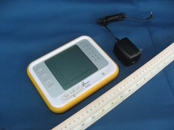
Click to zoom
Application Details
- Equipment Class
- DXT - Part 15 Low Power Transceiver, Rx Verified
- Date of Grant
- Jul 06, 2010
- Application Purpose
- Original Equipment
- Date of Application
- Jul 05, 2010
- Equipment Note
- HACCP Wireless Temperature Monitor
- Frequency Range
- 903.20000000 - 926.60000000
- Company
- Thermor Ltd.
- Country
- Canada
Documents & Files
Document Text
Text extracted from the exhibit documents filed with the FCC. Open a document above to read the original.
Users Manual
WIRELESS HACCP TEMPERATURE MANAGER INSTRUCTION MANUAL IMPORTANT INFORMATION TO READ BEFORE OPERATING THIS UNIT System Requirements: Windows: 2000, XP & Vista Excel: 2002, 2003, & 2007 Before fi rst use, check contents of box for the following components: MonitorAdaptor – 204TC 6 x Temperature Sensors – 201TCDatalogger Software – 209TC 4 x Cold Probes – 203TC (each)Screwdriver 2 x Hot Probes – 202TC (each)6 x Wall Mount Adhesive Strips 210TC 2 x 14’ Extension Cords – 208TC (each) 18 x AAA Batteries 4 x AA Batteries blue red 1.0 Introduction Congratulations on your purchase of the BIOS Professional Wireless HACCP Temperature Monitor. This unit was designed with food safety and convenience in mind. Monitoring temperature of hot and cold foods throughout the day can be time consuming and costly. This unit does all of the work, with accurate and precise readings stored so that data can be uploaded onto a personal computer, and kept for future reference. 1.1 Benefi ts of using the BIOS Professional HACCP Temperature Monitor • Reduce costs associated with managing HACCP • Allows users to store detailed historical data • Helps to reduce the risk of serving hazardous food • Monitors the time food is in a food temperature danger zone 1.2 Features The BIOS Professional Wireless HACCP Temperature Monitor is a wireless digital temperature device which is capable of reading, displaying and monitoring current temperatures from up to 30 temperature sensors. These long range sensors can transmit data through fl oors and from “out of sight” storage areas. Aside from current temperatures, the monitor’s LCD screen displays a real time clock and calendar, as well as maximum and minimum pre-set temperature settings. An audible alarm sounds when temperatures fall out of the pre-programmed range. In addition to the audio alert, green and red LED lights indicate temperature status for each sensor. The delay function defers the alarm for a user specifi ed period of 0, 15, 30, 45 or 60 minutes. Every 15 minutes, PC uploadable temperature data for each sensor is logged. Logged data is retrieved through the USB port and PC download software, as provided. 1.3 Care of the Device • Always wear a heat resistant glove to touch the stainless steel probe if being used in an area where temperature is high. • Wash stainless steel probes between uses, drying thoroughly. • Do not submerge the probe in water. Moisture inside the probe’s plug or the thermometer might cause an incorrect temperature reading. Always wipe the probe’s plug dry before plugging it into the sensor. • Do not subject the unit to excessive force, shock, dust, temperature or humidity that may result in malfunction, shorter electronic life span, or damage to the unit. • Do not place the monitor in direct sunlight, or let it come into contact with moisture or hot surfaces. • The probe is a sharp metal object. Take care when handling to avoid injuries. • Probes with red plugs are designed for monitoring high temperature while probes with blue plugs are designed for monitoring low temperature. Do not mix the usage of the two probes. • Do not expose any part of the probe directly to open fl ames. This will damage the temperature sensor. • Clean the probe with water and a mild detergent. Do not use corrosive or abrasive materials. Do not clean the probe in a dishwasher. • To clean the monitor or temperature sensor, wipe with a damp cloth. • Do not immerse the monitor or temperature sensor unit in water. If you spill liquid over the monitor or temperature sensor unit, dry immediately with a soft, lint-free cloth. • Do not tamper with the internal components of the monitor or temperature sensor units. 2.0 Getting Started Power up the monitor using the AC/DC adaptor included with the kit, before attempting to program. Insert 4 x AA batteries in the battery compartment on the back of the monitor for back up purposes. 2.1 About the Wireless HACCP Temperature Monitor This section describes the components of the unit. Monitor Front: Temperature Sensor Front: Back: Back: Monitor 1. LCD Screen 2. Green/Red LED Light 3. Scroll Buttons 4. Mode/Set Button 5. Temperature Max/Min Button 6. USB Port 7. AC/DC Socket 8. °C/°F Switch 9. Reset Button 10. Wall Mount Hole 11. Swing Out Stand Temperature Sensor 1. LCD Screen with Sensor Number 2. Alarm Delay Button 3. Mute/Sleep Button 4. Probe Socket 5. Red LED Light 6. Battery Compartment 7. Reset Button 8. Extension On/Off Slide Switch 10 8 11 9 87 6 R E S E T E X T O N O F F 1 5 4 3 5 3 2 4 6 1 7 2 2.2 About the LCD Screen on Monitor The LCD screen displays the sensor temperatures along with their actual and set Max/Min temperatures. It also displays a real time clock and calendar, low/no battery icon, AC/DC adaptor icon, REGistration mode icon, and SET TEMP mode icon. Actual Temperature Set and Recorded Max/Min Temperature Sensor Number Registration Mode Icon Time / Date AC/DC Adaptor Icon Low Battery Icon Set Temperature Mode Icon 3.0 Time & Date Setting NOTE: To maximize the benefi ts of this unit, accurate time and date should NOTE: To maximize the benefi ts of this unit, accurate time and date should NOTE: be set. 1. Press and hold MODE/SET until you hear a beep and the “24” begins to fl ash. 2. Use the or arrow to choose either a 24 or 12 hr clock. 3. Press MODE/SET to confi rm. 4. Once the clock beings to fl ash, repeat steps 2 and 3 to program the time. 5. The year will begin fl ashing. Use the and arrows to choose the correct year. 6. Press MODE/SET to confi rm. 7. “M” (month) and “D” (day) will begin to fl ash. Use the and arrows to select the format in which you would like the date to be displayed. Press MODE/SET to confi rm. 8. Use the and arrows to program the month and day. 9. Press MODE/SET to confi rm. 4.0 Using an Extension Cord An extension cord can be used if the cord on the probe is not long enough to reach the desired area from where the sensor is mounted. 1. Plug extension cord into temperature sensor. 2. Plu…
Text truncated - open the document above for the full version.
External Photos
INTERTEK TESTING SERVICE Report No.: HK10041148-1 Equipment Photographs Model : 200TC (External) FCC ID: VX5200TC IC: 6356A-200TX
ID Label/Location Info
INJECTION COLOR: COOL GREY 4U BACKGROUND SILKSCREEN COLOR : PMS 877C(SILVER) FONTS AND ICON SILKSCREEN COLOR : PMS425C (GREY) RUBBER KEY RUBBER LENS INJECTION COLOR: PMS116U (YELLOW) TEXTURE: YS20002B SE T T EMP REG USB FULL SEGMENT V.A SIZE 90X90mm RAR110(200TC) COLOR SPEC D C 6 V RUBBER COVER CAB COLOR: HIGH GLOSSY WHITE (white follow TARGET LINE BAR206) SILKSCREEN COLOR : GREY PMS425 FRONT CAB : INJECTION COLOR: WHITE (WHITE FOLLOW TARGET LINE BAR206) TEXTURE :YS20002B SILKSCREEN: GREY PMS 425C REAR CAB & STAND : EMBOSS RESET RUBBER RESET KEY : INJECTION COLOR :PMS430C INJECTION COLOR :WHITE C / F KEY : INJECTION COLOR: PMS116U (YELLOW) TEXTURE: YS20002B MODEL 200TC FCC ID : VX5200TC THIS DEVICE COMPLIES WITH PART 15 OF THE FCC RULES. OPERATION IS SUBJECT TO THE FOLLOWING TWO CONDITIONS : (1) THIS DEVICE MAY NOT CAUSE HARMFUL INTERFERENCE, AND (2) THIS DEVICE MUST ACCEPT ANY INTERFERENCE RECEIVED, INCLUDING INTERFERENCE THAT MAY CAUSE UNDESIRED OPERATION. IC: 6356A-200TC TEMP MAX/MIN MODE/SET CAB COLOR: HIGH GLOSSY WHITE (white follow TARGET LINE BAR206) Logo Silkscreen color : GREY PMS425 FRONT CAB :
Internal Photos
INTERTEK TESTING SERVICE Report No.: HK10041148 Equipment Photographs Model : 200TC (Internal) FCC ID: VX5200TC IC: 6356A-200TC INTERTEK TESTING SERVICE Report No.: HK10041148 Equipment Photographs Model : 200TC (Internal) FCC ID: VX5200TC IC: 6356A-200TC INTERTEK TESTING SERVICE Report No.: HK10041148 Equipment Photographs Model : 200TC (Internal) FCC ID: VX5200TC IC: 6356A-200TC INTERTEK TESTING SERVICE Report No.: HK10041148 Equipment Photographs Model : 200TC (Internal) FCC ID: VX5200TC IC: 6356A-200TC INTERTEK TESTING SERVICE Report No.: HK10041148 Equipment Photographs Model : 200TC (Internal) FCC ID: VX5200TC IC: 6356A-200TC
Operational Description
Technical Description of 200TC General 200TC is a wireless digital temperature device which is capable of reading, displaying and monitoring current temperatures from up to 30 temperature sensors. Aside from current temperatures, the monitor’s LCD screen displays a real time clock and calendar, as well as maximum and minimum pre-set temperature settings. An audible alarm sounds when temperatures fall out of the pre-programmed range. In addition to the audio alert, green and red LED lights indicate temperature status for each sensor. The delay function defers the alarm for a user specified period of 0, 15, 30, 45 or 60 minutes. Every 15 minutes, PC uploadable temperature data for each sensor is logged. Logged data is retrieved through the USB port and PC download software, as provided. MCU circuit U1 is the main MCU. It receives input signal from the AC detection (Q3), battery low detection circuit (R21, R22) and the keyboard (SW1 – SW4). It outputs data to the LCD and outputs the clock signal and data to the LED driver (U2). It communicates with the RF module (U17), USB interface (U201) and the EEPROM (U3) to transmit and receive data. RF module The RF module (U17) is a single-chip radio transceiver for the 915 MHz ISM band. The transceiver consists of a fully integrated frequency synthesiser, receiver chain with demodulator, a power amplifier, a crystal oscillator and a modulator. It has 10 frequency channels. The operating frequency range is from 903.2MHz to 926.6MHz. The modulation of nRF905 is Gaussian Frequency Shift Keying (GFSK) with a data rate of 100kbps. Deviation is ±50kHz. Frequency Table: Channel Frequency (MHz) 00 903.2 01 905.8 02 908.4 03 911.0 04 913.6 05 916.2 06 918.8 07 921.4 08 924.0 09 926.6 PRODUCT SPECIFICATION Main office: Nordic Semiconductor ASA - Vestre Rosten 81, N-7075 Tiller, Norway - Phone +4772898900 -Fax +4772898989 Revision: 1.4 Page 1 of 42 June 2006 FEATURES APPLICATIONS • True single chip GFSK transceiver in a small 32-pin package (32L QFN 5x5mm) • ShockBurst™ mode for low power operation • Power supply range 1.9 to 3.6 V • Multi channel operation – ETSI/FCC Compatible • Channel switching time <650μs • Extremely low cost Bill of Material (BOM) • No external SAW filter • Adjustable output power up to 10dBm • Carrier detect for "listen before transmit" protocols • Data Ready signal when a valid data packet is received or transmitted • Address Match for detection of incoming packet • Automatic retransmission of data packet • Automatic CRC and preamble generation • Low supply current (TX), typical 9mA @ -10dBm output power • Low supply current (RX), typical 12.5mA • Wireless data communication • Alarm and security systems • Home Automation • Remote control • Surveillance • Automotive • Telemetry • Industrial sensors • Keyless entry • Toys GENERAL DESCRIPTION nRF905 is a single-chip radio transceiver for the 433/868/915 MHz ISM band. The transceiver consists of a fully integrated frequency synthesiser, receiver chain with demodulator, a power amplifier, a crystal oscillator and a modulator. The ShockBurst TM feature automatically handles preamble and CRC. Configuration is easily programmable by use of the SPI interface. Current consumption is very low, in transmit only 9mA at an output power of -10dBm, and in receive mode 12.5mA. Built in power down modes makes power saving easily realizable. QUICK REFERENCE DATA Parameter Value Unit Minimum supply voltage 1.9 V Maximum transmit output power 10 dBm Data rate 50 kbps Supply current in transmit @ -10dBm output power 9 mA Supply current in receive mode 12.5 mA Temperature range -40 to +85 °C Typical Sensitivity -100 dBm Supply current in power down mode 2.5 μΑ Table 1 nRF905 quick reference data. Single chip 433/868/915 MHz Transceiver nRF905
Schematics
Circuit.SCH 200TC Aug.14.08 PAGE 2 OF 6 1 1.0 OF X.GONG X.GONG 3 APPROVED BY DATE: REVISION ISSUE ABCD 1 2 54 ABCD 6 LCD-PDD-019-A L C D TITLEDOC NO.MODEL NO.CAD REF.PAGE APPD. CHKDDRAWNDIVISION SCHEMATIC DIAGRAMIDT TECHNOLOGY LTD. KZHANG KZHANG X.GONG LS01426 FIRST RELEASE FOR PRODUCTION 5 1 VSS 2 XIN 3 XOUT 4 TEST 5 VDD 6 P21 7 P22 8 RESET 9 P20 10 P60 11 P61 12 P62 13 P63 14 P64 15 P65 16 P66 17 P67 18 VAREF 19 P17/SEG59 20 P16/SEG58 21 P15/SEG57 22 P14/SEG56 23 P13/SEG55 24 P12/SEG54 25 P11/SEG53 26 P10/SEG52 27 P33/SEG51 28 P32/SEG50 29 P31/SEG49 30 P30/SEG48 80 COM1 79 COM0 78 SEG0 77 SEG1 76 SEG2 75 SEG3 74 SEG4 73 SEG5 72 SEG6 71 SEG7 70 SEG8 69 SEG9 68 SEG10 67 SEG11 66 SEG12 65 SEG13 64 SEG14 63 SEG15 62 SEG16 61 SEG17 60 SEG18 59 SEG19 58 SEG20 57 SEG21 56 SEG22 55 SEG23 54 SEG24 53 SEG25 52 SEG26 51 SEG27 81 COM2 82 COM3 83 COM4 84 P34/COM5 85 P35/COM6 86 P36/COM7 87 P70/COM8 88 P71 89 P72 90 P73 91 P74 92 P75 93 P76 94 P77 95 V4 96 V3 97 V2 98 V1 99 C1 100 C0 50 SEG28 49 SEG29 48 SEG30 47 SEG31 46 SEG32 45 SEG33 44 SEG34 43 SEG35 42 SEG36 41 SEG37 40 SEG38 39 SEG39 38 P50/SEG40 37 P51/SEG41 36 P52/SEG42 35 P53/SEG43 34 P54/SEG44 33 P55/SEG45 32 P56/SEG46 31 P57/SEG47 U1 TMP86FM25A 32K FLASH ROM 2K RAM X1 8MHz X2 32.768KHz C1 18P C2 18P J13 C4 5-35P C3 18P C5 0.1uF C6 0.1uF C7 0.1uF C8 0.1uF C9 0.1uF 1 COM0 2 COM1 3 COM2 4 COM3 5 COM4 6 COM5 7 COM6 8 COM7 9 COM2 10 COM1 11 COM0 12 SEG16 13 SEG0 14 SEG1 15 SEG2 16 SEG3 17 SEG4 18 SEG5 19 SEG6 20 SEG7 21 COM0 22 SEG16 23 SEG8 24 SEG9 25 SEG10 26 SEG11 27 SEG12 28 SEG13 29 SEG14 30 SEG15 31 SEG16 32 COM0 33 COM1 34 COM2 35 COM7 36 COM6 37 COM5 38 COM4 39 COM3 40 COM2 41 COM1 42 COM0 43 SEG16 PIN1 LCD_43PIN 1 SEG17 2 SEG18 3 SEG19 4 SEG20 5 SEG21 6 SEG22 7 SEG23 8 SEG24 9 SEG16 10 SEG25 11 SEG26 12 SEG27 13 SEG28 14 SEG29 15 SEG30 16 SEG31 17 SEG32 18 SEG16 19 COM0 20 COM1 21 COM2 22 COM3 23 COM4 24 COM5 25 COM6 26 COM7 27 COM0 28 COM1 29 COM2 30 SEG16 31 SEG33 32 SEG34 33 SEG35 34 SEG36 35 SEG37 36 SEG38 37 SEG39 38 SEG16 39 COM0 40 SEG40 41 SEG41 42 SEG42 43 SEG43 44 SEG44 45 SEG45 46 SEG46 47 SEG47 48 SEG48 49 SEG49 50 SEG50 51 SEG51 52 SEG52 53 SEG40 54 COM7 55 COM6 56 COM5 57 COM4 58 COM3 59 COM2 60 COM1 61 COM0 PIN2 LCD_61PIN J1 J2 R1 100K R2 100K R14 100K R15 10K R16 100K R17 100K R18 100K R19 10K R20 10K R21 200K R22 100K R23 10K R25 100K R26 100K R27 100K R28 100K R29 100K C10 1uF SW6 9 GND 63 IOD2 59 IOC2 58 IOC1 36 SEG10 35 SEG9 34 SEG8 33 SEG7 32 SEG6 31 SEG5 30 SEG4 29 SEG3 28 SEG2 27 SEG1 26 COM9 25 COM8 24 COM7 23 COM6 22 COM5 19 COM2 18 COM1 21 COM4 20 COM3 13 VDD3 62 IOD1 12 VPP 11 VDD2 17 CPU2 7 CFIN 16 CPU1 3 RCIN 6 FROUT 64 IOD3 5 FRIN 4 RCOUT 66 SEG40 8 CFOUT 1 XIN 65 IOD4 57 IOB4 56 IOB3 55 IOB2 60 IOC3 61 ICO4 15 CPU0 37 SEG11 38 SEG12 39 SEG13 40 SEG14 41 SEG15 42 SEG16 43 SEG17 44 SEG18 45 SEG19 46 SEG20 47 SEG21 48 SEG22 49 SEG23 50 SEG24 51 SEG25 52 SEG26 53 SEG27 14 VDD4 2 XOUT 54 IOB1 67 SEG41 68 RESET 69 INT 70 TEST 10 VDD1 U2 TM8795 J6 X3 32.768KHz C28 18P C29 18.P Q17 R4 100k R62 100k R63 47k R64 100k D6 1N4148 R24 100K R3 47k R74 56K TEST VDD-3V RESET KEY1 KEY2 NORDIC_MISO LOW_BAT KEYTONE_HIGHT NORDIC_CD NORDIC_TRX_CE NORDIC_TXEN NORDIC_MOSI NORDIC_SCKNORDIC_CSN UART_RXD UART_TXD TENX_DATA_OUT KEYTONE USB_CONNECTED ADAPTOR C/F_SLIDE_SWITCH NORDIC_DR LCD_VDD SEG[0:52] SEG0 SEG1 SEG2 SEG3 SEG4 SEG5 SEG6 SEG7 SEG8 SEG9 SEG10 SEG11 SEG12 SEG13 SEG14 SEG15 SEG16 SEG17 SEG18 SEG19 SEG20 SEG21 SEG22 SEG23 SEG24 SEG25 SEG26 SEG27 SEG28SEG29SEG30SEG31SEG32SEG33SEG34SEG35SEG36SEG37SEG38SEG39SEG40SEG41SEG42SEG43SEG44SEG45SEG46SEG47 SEG48 SEG49 SEG50 SEG51 COM[0:7] COM0 COM1 COM2COM3COM4COM5COM6COM7 COM[0:7] SEG[0:52] SEG[0:52] COM0 COM1 COM2 COM3 COM4 COM5 COM6 COM7 COM0 COM1 COM2 SEG16 SEG0 SEG1 SEG2 SEG3 SEG4 SEG5 SEG6 SEG7 SEG8 SEG9 SEG10 SEG11 SEG12 SEG13 SEG14 SEG15 SEG16 COM0 SEG16 COM0 COM1 COM2 COM3 COM4 COM5 COM6 COM7 SEG16 COM0 COM1 COM2 COM0 COM1 COM2 COM3 COM4 COM5 COM6 COM7 COM0 COM1 COM2 COM0 COM0 COM1 COM2 COM3 COM4 COM5 COM6 COM7 SEG17 SEG18 SEG19 SEG20 SEG21 SEG22 SEG23 SEG24 SEG25 SEG26 SEG27 SEG28 SEG29 SEG30 SEG31 SEG32 SEG16 SEG16 SEG16 SEG33 SEG34 SEG35 SEG36 SEG37 SEG38 SEG39 SEG16 SEG40 SEG41 SEG42 SEG43 SEG44 SEG45 SEG46 SEG47 SEG48 SEG49 SEG50 SEG51 SEG52 SEG52 SEG40 EEPROM_DATA EEPROM_CLK VDD-3V VDD-3V V_BATT LOW_BAT TENX_CLK VDD-3V VPP INT TENX_RESET LED1LED2LED3LED4LED5LED6LED7LED8LED9LED10LED11LED12 VDD-3V VDD2 TENX_CLK TENX_DATA_OUT VDD-3V VDD-3V 12/24_BONDING_OPTION DM/MD_OPTION 12/24_BONDING_OPTION DM/MD_OPTION TENX_RESET RESET Circuit.SCH 200TC Aug.14.08 PAGE 3 OF 6 2 1.0 OF X.GONG X.GONG 3 APPROVED BY DATE: REVISION ISSUE ABCD 1 2 54 ABCD 6 LCD-PDD-019-A L C D TITLEDOC NO.MODEL NO.CAD REF.PAGE APPD. CHKDDRAWNDIVISION SCHEMATIC DIAGRAMIDT TECHNOLOGY LTD. KZHANG KZHANG X.GONG LS01426 FIRST RELEASE FOR PRODUCTION 5 (MCU-POWER) (RF-POWER) BATT1 4X2A 6.0V D1 1N4148 D2 1N4148 L1 100uH + C12 10uF C13 0.1uF C14 0.1uF + C15 10uF D3 1N4148 D4 1N4148 1 VSS 2 VDD 3 OUT U4 5V R30 10 ohm + C16 10uF C17 0.1uF C18 0.1uF + C19 10uF 1 VSS 2 VDD 3 OUT U5 3V C20 0.1uF + C21 10uF + C22 10uF C23 0.1uF R31 100K R32 100K R33 1M 1 VSS 2 VDD 3 OUT U6 3V Q3 BC846 + C24 10uF C25 0.1uF C26 0.1uF R34 10ohm C27 0.1uF DCJACK1 GND V_ADAPTER V_BATT RF_3V +3V GND ADAPTOR VDD-3V +3V VIN VDD-3V LCD_VDD +5V Circuit.SCH 200TC Aug.14.08 PAGE4 OF 6 3 1.0 OF X.GONG X.GONG 3 APPROVED BY DATE: REVISION ISSUE ABCD 1 2 54 ABCD 6 LCD-PDD-019-A L C D TITLEDOC NO.MODEL NO.CAD REF.PAGE APPD. CHKDDRAWNDIVISION SCHEMATIC DIAGRAMIDT TECHNOLOGY LTD. KZHANG KZHANG X.GONG LS01426 FIRST RELEASE FOR PRODUCTION 5 R5 56K R6 100K R7 100K SW1SW2 R8 56K R9 100K R10 100K SW3SW4 BZ1 R11 180 R12 2.2K R13 2.2K Q1 BC846 Q4 BC846 12345678 J8 SW5 R35 100K R36 10K R37 10K LED1 R38 22K R39 820 Q5 BC846 LED2 R40 22K R41 820 Q6 BC846 LED3 R42 22K R43 820 Q7 BC846 LED4 R44 22K R45 820 Q8 BC846 LED5 R46 22K R47 820 Q9 BC846 LED6 R48 22K R49 820 Q10 BC846 LED7 R50 22K R51 510 Q11 BC846 LED8 R52 22K R53 510 Q12 BC846 LED9 R54 22K R55 510 Q13 BC846 LE…
Text truncated - open the document above for the full version.
Test Report
INTERTEK TESTING SERVICES Report No.: HK10041148-1 Sample No.: 1/3 Code: FCC15C_c / Effective Date: 04 Aug 2009 ( of ) Bandedge Plot – Pursuant to FCC Part 15 Section 15. 249 Requirement (Pass)
Test Report
Report no.: HK10041148-1 PC’s AC Mains TX mode Ctrl No.: 150 kHz30 MHz 1 PK CLRWR 2 AV CLRWR SGL TDS 6DB dBμV dBμV AC RBW 9 kHz MT 1 s PREAMP OFFAtt 10 dB AUTO 1 MHz10 MHz 0 10 20 30 40 50 60 70 80 90 100 CF15MAV CF15MQP D11481A4 Date: 15.MAY.2010 10:34:33 Report no.: HK10041148-1 PC’s AC Mains TX mode Ctrl No.: EDIT PEAK LIST (Final Measurement Results) Trace1: CF15MQP Trace2: CF15MAV Trace3: --- TRACE FREQUENCY LEVEL dBμV DELTA LIMIT dB 1 Quasi Peak 154.5 kHz 47.57 N gnd -18.17 2 CISPR Average195 kHz 34.44 L1 gnd -19.37 1 Quasi Peak 213 kHz 40.82 N gnd -22.26 1 Quasi Peak 294 kHz 34.13 N gnd -26.28 2 CISPR Average514.5 kHz 24.64 L1 gnd -21.35 2 CISPR Average708 kHz 24.47 L1 gnd -21.52 2 CISPR Average1.0275 MHz 26.22 L1 gnd -19.77 2 CISPR Average1.4775 MHz 26.79 L1 gnd -19.20 2 CISPR Average2.0535 MHz 27.51 L1 gnd -18.48 2 CISPR Average2.247 MHz 28.50 N gnd -17.49 1 Quasi Peak 2.886 MHz 36.81 L1 gnd -19.18 1 Quasi Peak 3.3405 MHz 38.95 L1 gnd -17.04 2 CISPR Average3.534 MHz 30.07 N gnd -15.92 1 Quasi Peak 4.8795 MHz 38.03 L1 gnd -17.96 2 CISPR Average4.8795 MHz 32.53 L1 gnd -13.46 2 CISPR Average5.7795 MHz 27.98 L1 gnd -22.01 2 CISPR Average9.888 MHz 30.56 L1 gnd -19.43 1 Quasi Peak 11.1075 MHz 34.30 L1 gnd -25.69 2 CISPR Average12.9705 MHz 28.91 L1 gnd -21.08 2 CISPR Average19.005 MHz 26.79 L1 gnd -23.20 D11481A4 Date: 15.MAY.2010 10:34:21
Test Report
- The test report only allows to be revised within the retention period unless further standard or the requirement was noticed. - This report is for the exclusive use of Intertek's Client and is provided pursuant to the agreement between Intertek and its Client. Intertek's responsibility and liability are limited to the terms and conditions of the agreement. Intertek assumes no liability to any party, other than to the Client in accordance with the agreement, for any loss, expense or damage occasioned by the use of this report. Only the Client is authorized to permit copying or distribution of this report and then only in its entirety. Any use of the Intertek name or one of its marks for the sale or advertisement of the tested material, product or service must first be approved in writing by Intertek. The observations and test results in this report are relevant only to the sample tested. This report by itself does not imply that the material, product, or service is or has ever been under an Intertek certification program. Intertek Testing Services Hong Kong Ltd. 2/F., Garment Centre, 576 Castle Peak Road, Kowloon, Hong Kong. Tel: (852) 2173 8888 Fax: (852) 2785 5487 Website: www.hk.intertek-etlsemko.com TEST REPORT Report No.: HK10041148-1 Thermor Limited Application For Certification (Original Grant) (FCC ID: VX5200TC) (IC: 6356A-200TC) Transceiver Prepared and Checked by: Approved by: Signed On File Benny Lau/sl Engineer Chan Chi Hung, Terry Senior Lead Engineer Date: June 30, 2010 INTERTEK TESTING SERVICES Report No.: HK10041148-1 FCC ID: VX5200TC IC: 6356A-200TC i GENERAL INFORMATION Thermor Limited BRAND NAME: Bios Professional, MODEL: 200TC FCC ID: VX5200TC IC: 6356A-200TC Grantee: Thermor Limited Grantee Address: 16975 Leslie Street, Newmarket, ON L3Y 9A1, Canada. Contact Person: Chris Reid Tel: (905) 952-3737 Fax: (905) 952-3731 e-mail: [email protected] Manufacturer: IDT Technogolgy Ltd. Manufacturer Address: 9/F, Kaiser Estate, 41 Man Yue Street, Hung Hom, Kowloon, Hong Kong Brand Name: Bios Professional Model: 200TC Type of EUT: Transceiver Description of EUT: HACCP Wireless Temperature Monitor Serial Number: N/A FCC ID / IC: VX5200TC / 6356A-200TC Date of Sample Submitted: April 22, 2010 Date of Test: May 15, 2010 Report No.: HK10041148-1 Report Date: June 30, 2010 Environmental Conidtions: Temperature: +10 to 40°C Humidity: 10 to 90% INTERTEK TESTING SERVICES Report No.: HK10041148-1 FCC ID: VX5200TC IC: 6356A-200TC ii SUMMARY OF TEST RESULT Thermor Limited BRAND NAME: Bios Professional, MODEL: 200TC FCC ID: VX5200TC IC: 6356A-200TC TEST SPECIFICATION REFERENCE RESULTS Maximum Peak Output Power 15.247(b), (c) / RSS-210 A8.4 N/A Hopping Channel Carrier Frequencies Separation 15.247(e) / RSS-210 A8.1 N/A 20dB Bandwidth of the Hopping Channel 15.247(a) / RSS-210 A8.1 N/A Number of Hopping Frequencies 15.247(e) / RSS-210 A8.1 N/A Average Time of Occupancy of Hopping Frequency 15.247(e) / RSS-210 A8.1 N/A Antenna Conducted Spurious Emissions 15.247(d) / RSS-210 A8.5 N/A Radiated Spurious Emissions 15.247(d) / RSS-210 A8.5 N/A RF Exposure Compliance 15.247(i) / RSS-Gen 5.5 N/A Transmitter Power Line Conducted Emissions 15.207 / RSS-Gen 7.2.2 Pass Transmitter Field Strength 15.227 / RSS-310 3.8 N/A Transmitter Field Strength 15.229 / RSS-210 A2.7 N/A Transmitter Field Strength, Bandwidth and Timing Requirement 15.231(a) / RSS-210 A1.1.1 N/A Transmitter Field Strength, Bandwidth and Timing Requirement 15.231(e) / RSS-210 A1.1.5 N/A Transmitter Field Strength and Bandwidth Requirement 15.239 / RSS-210 A2.8 N/A Transmitter Field Strength and Bandwidth Requirement 15.249 / RSS-210 A2.9 Pass Receiver Radiated Emissions RSS-210 2.6 Pass Transmitter Field Strength and Bandwidth Requirement 15.235 / RSS-310 3.9 N/A Digital Device Radiated Emissions 15.109 / ICES-003 N/A Digital Device Conducted Emissions 15.107 / ICES-003 N/A Note: 1. The EUT uses a permanently attached antenna which, in accordance to section 15.203, is considered sufficient to comply with the pervisions of this section. 2. Pursuant to FCC part 15 Section 15.215(c), the 20 dB bandwidth of the emission was contained within the frequency band designated (mentioned as above) which the EUT operated. The effects, if any, from frequency sweeping, frequency hopping, other modulation techniques and frequency stability over excepted variations in temperature and supply voltage were considered. INTERTEK TESTING SERVICES Report No.: HK10041148-1 FCC ID: VX5200TC IC: 6356A-200TC iii Table of Contents 1.0 General Description........................................................................................ 1 1.1 Product Description ........................................................................................... 1 1.2 Related Submittal(s) Grants............................................................................... 1 1.3 Test Methodology.............................................................................................. 1 1.4 Test Facility ....................................................................................................... 1 2.0 System Test Configuration ............................................................................. 2 2.1 Justification ....................................................................................................... 2 2.2 EUT Exercising Software................................................................................... 2 2.3 Special Accessories .......................................................................................... 2 2.4 Equipment Modification ..................................................................................... 2 2.5 Measurement Uncertainty.................................................................................. 2 2.6 Support Equipment List and Description ............................................................ 2 3.0 Emission Results .....................................................…
Text truncated - open the document above for the full version.
Test Setup Photos
INTERTEK TESTING SERVICE Report No: HK10041148-1 FCC ID: VX5200TC IC: 6356A-200TX i Configuration Photographs Worst-Case Line-Conducted Emissions (Front View) Model : 200TC Figure 1 INTERTEK TESTING SERVICE Report No: HK10041148-1 FCC ID: VX5200TC IC: 6356A-200TX ii Configuration Photographs Worst-Case Line-Conducted Emissions (Back View) Model : 200TC Figure 2 INTERTEK TESTING SERVICE Report No: HK10041148-1 FCC ID: VX5200TC IC: 6356A-200TX iii Configuration Photographs Worst-Case Line-Conducted Emissions (Side View) Model : 200TC Figure 3
Test Setup Photos
INTERTEK TESTING SERVICE Report No: HK10041148-1 Configuration Photographs Worst-Case Radiated Emissions (Front View) Model : 200TC Figure 1 FCC ID: VX5200TC IC: 6356A-200TX INTERTEK TESTING SERVICE Report No: HK10041148-1 Configuration Photographs Worst-Case Radiated Emissions (Back View) Model : 200TC Figure 2 FCC ID: VX5200TC IC: 6356A-200TX
Contact Information
Applicant
Joanna Biniek
Technical Contact
Intertek Testing Services Hong Kong LtdBen Ho
[email protected]852-21738505
2/F Garment Centre · Kowloon · Hong Kong
Non-Technical Contact
Intertek Testing Services Hong Kong LtdBen Ho
[email protected]852-21738505
Test Firm
Intertek Testing Services Hong Kong Ltd.Billy Chow
Technical Specifications
| # | Rule Parts | Frequency Range | Power Output |
|---|---|---|---|
| 1 | 15C | 903.2 MHz - 926.6 MHz | - |
Other Applications from Thermor Ltd.

VX5-375TX
Jun 27, 2014transmitter
Equipment Class
DSC - Part 15 Security/Remote Control Transmitter
VX5-375RX
Jun 27, 2014JUMBO SCREEN WEATHER STATION
Equipment Class
CYY - Communications Receiver used w/Pt 15 Transmitter
VX5-348TX
Jan 15, 2013Outdoor temperature and humidity sensor
Equipment Class
DSC - Part 15 Security/Remote Control Transmitter
VX5-336TX
Sep 10, 2012OUTDOOR TEMPERATURE AND HUMIDITY SENSOR
Equipment Class
DSC - Part 15 Security/Remote Control Transmitter
VX5-336RX
Sep 07, 2012DELUXE INDOOR/OUTDOOR THERMOMETER WITH COMFORT INDICATOR
Equipment Class
CYY - Communications Receiver used w/Pt 15 Transmitter