W2E-ITAGV16Wireless GPS tracking device using 802.15.4
iControl Incorporated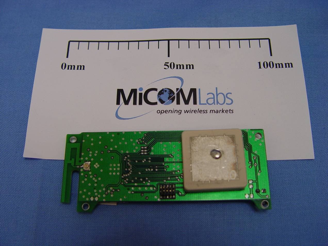
Click to zoom
Application Details
- Equipment Class
- DTS - Digital Transmission System
- Date of Grant
- Jan 24, 2010
- Application Purpose
- Original Equipment
- Date of Application
- Jan 24, 2010
- Equipment Note
- Wireless GPS tracking device using 802.15.4
- Frequency Range
- 2405.00000000 - 2480.00000000
- Company
- iControl Incorporated
- Country
- United States
Documents & Files
Document Text
Text extracted from the exhibit documents filed with the FCC. Open a document above to read the original.
Users Manual
iControl Incorporated http://www.iControl‐Inc.com iTAG Module Integrated iTAG With Enclosure iTAG Reader utilizing an Internal iTAG Module iTAG Module Operating Manual Background. The iTAG is 2.4GHz bi‐directional radio transceiver that is integrated with a GPS receiver, motion detecting sensor, and non‐volatile flash memory for data storage. A User may configure the device to operate as a Radio Frequency Identification Device (RFID) for tracking shipping containers in a worldwide supply chain using the Marine Asset Tag Tracking System (MATTS) communication protocol. An iTAG module utilizes a low power, wireless, radio operating in the 2.4 GHz band as its primary mode of communication. The wireless radio operates in compliance with IEEE Standard 802.15.4‐2006. The iTAG GPS receiver is User configurable to periodically determine the iTAG’s global location using data from the USAF GPS constellation. The module may operate as stand alone device or may be used as a radio and GPS receiver for communication devices that are apart of large systems or security devices. The User interface for the module is via a twenty (20) pin connector on the bottom of the module. Figure 1 iTAG Devices iControl Incorporated http://www.iControl‐Inc.com iTAG Radio Operation. The iTAG is controlled via a serial port interface for initial configuration and checkout. All commands for controlling the radio are identified in the iTAG Command List. Once a User as completed the initial iTAG configuration, complete control and operation of the iTAG can be accomplished through the radio link interface using the same commands available in the iTAG Command List. The radio in the iTAG is nominally operated in a power saving mode with the receiver periodically enabled and “listening” for commands or data requests. A key element to the power saving mode is the principle of “tag‐talks‐last”. In this mode, battery power is conserved by only responding to messages that are sent directly to the specific iTAG MAC address or mutual broadcast address. For a majority of iTAG operation, the iTAG is in a deep power saving mode (~98% of the time). The iTAG will only transmit when it receives a properly encrypted message during its receiver active period. The encrypted message directed to the iTAG may include information about which channel the iTAG should use for further transmissions. Once, the communication parameters are exchanged, there will typically be a period a several seconds of active radio transmission as the iTAG relays data. The data transmitted may either be security data destined for government servers, and/or commercial data destined for the end customer. This data may originate from internal flash storage or it may be received and relayed from another compatible device. Other Components. In addition to the wireless radio, several other electronic devices are used by the iTAG. 1. The low‐power GPS receiver is powered periodically to receive GPS signals. The GPS receiver is typically powered for less than one minute per hour; however the frequency of GPS fixes is highly configurable to accommodate a variety of requirements and may vary based on other inputs. 2. A low‐power MEMS accelerometer is used to detect motion. Using a patent pending process, the iTAG utilize the motion detection sensor to establish if a new GPS fix is required. 3. Analog signals may be monitored to detect security related information (e.g. temperature, enclosure breach, installation security etc.) 4. Two RS‐232 serial UARTs are available for the User to communicate data to the module from secondary systems to transmit data via the radio transceiver. iControl Incorporated http://www.iControl‐Inc.com Functional Block Diagram. The iTAG module integrates a GPS receiver, a 2.4Ghz radio, and a low power microprocessor . The iTAG module also includes a software User interface that provides commands for controlling the radio functions, sending data, retrieving GPS location , and uploading stored data. Note: Please refer to the iTAG Command List for a complete list of operating commands that control the iTAG module. The iTAG module is equipped with an integrated trace antenna rated at 3.0 dBi. Most embedded mobile applications will utilize the integral antenna provided with the iTAG module. Optionally, a micro coax connector may be utilized to connect external antenna to the iTAG module. iControl can provide iTAG modules with external antenna connectors that are certified and licensed for external antenna operations. NOTE: Users may not modify the antenna or it’s connection in anyway or risk violating radio law. Figure 2 iTAG Block Diagram iControl Incorporated http://www.iControl‐Inc.com Absolute Maximum Ratings. Under no circumstances must the absolute maximum ratings giving in this table be violated. Stress exceeding one or more of the limiting values may cause permanent damage to the device. Parameter Min Max Units Condition Supply Voltage -0.3 6.0 V All supply pins must have same voltage Voltage on any digital pin -0.3 3.6 V Input RF level 10 dBm Storage temperature range -50 150 C Operating ambient temperature -40 85 C Figure 3 Maximum Ratings iControl Incorporated http://www.iControl‐Inc.com General Characteristics. iControl Incorporated http://www.iControl‐Inc.com iTAG Radio Specification (Transmit). iControl Incorporated http://www.iControl‐Inc.com iTAG Radio Specification (Receive). iControl Incorporated http://www.iControl‐Inc.com OEM Installation Instruction: An OEM integrator utilizes the 2x10 x2mm pin header connector on the bottom of the iCHIME. To apply power, utilize serial data, and connect to analog interfaces, the OEM must provide a 2x10 x 2mm pin socket on their integrating electronics. Interface Specification. The interface diagram noted below is for the mating connector on the User’s electronics. All interfaces to the radio are buffered to prevent User interface electronics from interfering with the operation of the radio. PIN Name Typ…
Text truncated - open the document above for the full version.
Cover Letter(s)
Federal Communications Commission Authorization and Evaluation Division Equipment Authorization Branch 7435 Oakland Mills Road Columbia, MD 21046 12/3/2009 To whom it may concern: We, the undersigned, hereby authorize Eurofins ETS Product Service GmbH to act on our behalf in all matters relating to applications for equipment authorization FCC ID: W2E-ITAGV16 including the signing of all documents related to these matters. Any and all acts carried out by Eurofins ETS Product Service GmbH on our behalf shall have the same effect as acts of our own. We also hereby certify that no party to this application is subject to a denial of benefits, including FCC benefits, pursuant to Section 5301 of the Anti-Drug Abuse Act of 1988, 21 U.S.C. 862. Sincerely, Signature Fred Tubb President & CEO iControl Inc.
Cover Letter(s)
Federal Communications Commission Equipment Authorization Branch 7435 Oakland Mills Road Columbia, MD 21046 12/3/2009 Request for Confidentiality Company name: iControl Incorporated. FCC ID: W2E-ITAGV16 FCC Part 15 Certification Gentlemen, In accordance with 0.459 of CFR 47, iControl hereby requests confidentiality of all circuit descriptions, circuit diagrams and parts list attachments for the subject application. These documents contain detailed system and equipment description and related information about the product which iControl considers to be proprietary, confidential and a custom design and otherwise would not release to the general public. Since the design is a basis from which future technological products will evolve, iControl considers that this information would be of benefit to its competitors and that the disclosure of the information in these documents would give competitors an unfair advantage in the market. Sincerely, Signature Fred Tubb President & CEO iControl Incorporated 3235 Kifer Rd, Suite 260 Santa Clara, CA 95051
Cover Letter(s)
http://www.iControl-Inc.com 3235 Kifer, Suite 260 Santa Clara, CA 95051 December 10 th , 2009 Subject: Modular Approval Requirements for FCC certification for iControl Incorporated. Reference: FCC ID: W2E-ITAGV16 Dear Application Examiner, iControl Incorporated iTAG is seeking modular approval for FCC ID: W2E-ITAGV16. The radio meets the requirements for a modular approval as detailed in the FCC public notice DA00-1407. Compliance to each requirements is described below: 1. The modular transmitter must have its own RF shielding. WE COMPLY 2. The modular transmitter must have buffered modulation/data inputs. WE COMPLY 3. The modular transmitter must have its own power supply regulation. WE COMPLY 4. The modular transmitter must comply with the antenna requirements of Section 15.203 and 15.204(c). The antenna must either be permanently attached or employ a “unique” antenna coupler (at all connections between the module and the antenna, including the cable). WE COMPLY 5. The modular transmitter must be tested in a stand-alone configuration, WE COMPLY 6. The modular transmitter must be labeled with its own FCC ID number. WE COMPLY 7. The modular transmitter must comply with any specific rule or operating requirements applicable to the transmitter and the manufacturer must provide adequate instructions along with the module to explain any such requirements. WE COMPLY 8. The modular transmitter must comply with any applicable RF exposure requirements. WE COMPLY Sincerely, Fred Tubb President & CEO iControl Incorporated.
External Photos
the wireless lab 24 September 2009 ICON08 – iTAG Internal Photographs iTAG - Front MiCOM Labs, 440 Boulder Court, Suite 200, Pleasanton, CA 94566 Tel: +1 (925) 462-0304, Fax: +1 (925) 462-0306, Web: www.micomlabs.com the wireless lab iTAG - Rear Page 2 of 2
ID Label/Location Info
Label Location iTAG
Internal Photos
the wireless lab 24 September 2009 ICON08 – iTAG Internal Photographs iTAG - Front MiCOM Labs, 440 Boulder Court, Suite 200, Pleasanton, CA 94566 Tel: +1 (925) 462-0304, Fax: +1 (925) 462-0306, Web: www.micomlabs.com the wireless lab iTAG - Rear Page 2 of 2
RF Exposure Info
440 Boulder Court, Suite 200, Pleasanton, California 94566, USA Tel.: +1 925 462 0304, Fax: +1 925 462 0306 www.micomlabs.com December 9, 2009 ICON08 –iTAG 1.1.1. Maximum Permissible Exposure FCC, Part 15 Subpart C §15.247(i) Industry Canada RSS-Gen §5.5 Calculations for Maximum Permissible Exposure Levels Power Density = Pd (mW/cm 2 ) = EIRP/(4πd 2 ) EIRP = P * G P = Peak output power (mW) G = Antenna numeric gain (numeric) d = Separation distance (cm) Numeric Gain = 10 ^ (G (dBi)/10) Because the EUT belongs to the General Population/Uncontrolled Exposure the limit of power density is 1.0 mW/cm 2 Freq. Band (GHz) Antenna Gain (dBi) Numeric Gain (numeric) Peak Output Power (dBm) Peak Output Power (mW) Calculated Safe Distance @ 1mW/cm 2 Limit(cm) Minimum Separation Distance (cm) 2.4 14.0 25.12 +16.72 46.99 9.7 20.0 *Note: for mobile or fixed location transmitters the minimum separation distance is 20cm, even if calculations indicate the MPE distance to be less. Specification Maximum Permissible Exposure Limits §15.247(i) Systems operating under the provisions of this section shall be operated in a manner that ensures that the public is not exposed to radio frequency levels in excess of the Commission’s guidelines. FCC §1.1310 Limit = 1mW / cm 2 from 1.310 Table 1 RSS-Gen §5.5 Before equipment certification is granted, the applicable requirements of RSS-102 shall be met.
Test Report
COVER PAGE Test of iControl, iTAG 802.15.4 To: FCC 47 CFR Part 15.247 & IC RSS-210 Test Report Serial No.: ICON08-A2 Rev A TITLE PAGE TEST REPORT FROM Test of iControl, iTAG 802.15.4 to To FCC 47 CFR Part 15.247 & IC RSS-210 Test Report Serial No.: ICON08-A2 Rev A This report supersedes: None Applicant: iControl, Incorporated 3235 Kifer, Suite 260 Santa Clara California, 95051 USA Product Function: 802.15.4 Radio Frequency Identification (RFID) Copy No: pdf Issue Date: 8th December 2009 MiCOM Labs is an ISO 17025 Accredited Testing Laboratory This Test Report is Issued Under the Authority of; MiCOM Labs, Inc. 440 Boulder Cour t, Suite 200 Pleasanton, CA 94566 USA Phone: +1 (925) 462-0304 Fax: +1 (925) 462-0306 www.micomlabs.com CERTIFICATE #2381.01 This test report may be reproduced in full only. The document may only be updated by MiCOM Labs personnel. Any changes will be noted in the Document History section of the report. Title: iControl, iTAG 802.15.4 To: Serial #: Issue Date: Page: FCC 47 CF R Part 15.247 & IC RSS-210 ICON08-A2 Rev A 8th December 2009 3 of 95 This test report may be reproduced in full only. The document may only be updated by MiCOM Labs personnel. Any changes will be noted in the Document History section of the report. MiCOM Labs, 440 Boulder Court, Suite 200, Pleasanton, CA 94566 USA, Phone: 925.462.0304, Fax: 925.462.0306, www.micomlabs.com This page has been left intentionally blank Title: iControl, iTAG 802.15.4 To: Serial #: Issue Date: Page: FCC 47 CF R Part 15.247 & IC RSS-210 ICON08-A2 Rev A 8th December 2009 4 of 95 This test report may be reproduced in full only. The document may only be updated by MiCOM Labs p ersonnel. Any changes will be noted in the Document History section of the report. MiCOM Labs, 440 Boulder Court, Suite 200, Pleasanton, CA 94566 USA, Phone: 925.462.0304, Fax: 925.462.0306, www.micomlabs.com TABLE OF CONTENTS ACCREDITATION, LISTINGS and RECOGNITION......................................................... 5 1. TEST RESULT CERTIFICATE ................................................................................... 8 2. REFERENCES AND MEASUREMENT UNCERTAINTY .......................................... 9 2.1. Normative References ............................................................................................... 9 2.2. Test and Uncertainty Procedures .............................................................................. 9 3. PRODUCT DETAILS AND TEST CONFIGURATIONS .......................................... 10 3.1. Technical Details ..................................................................................................... 10 3.2. Scope of Test Program ............................................................................................ 11 3.3. Equipment Model(s) and Serial Number(s) ............................................................. 13 3.4. Antenna Details ....................................................................................................... 13 3.5. Cabling and I/O Ports .............................................................................................. 14 3.6. Test Configurations.................................................................................................. 14 3.7. Equipment Modifications.......................................................................................... 14 3.8. Deviations from the Test Standard .......................................................................... 15 4. TEST SUMMARY ...................................................................................................... 16 5. TEST RESULTS ........................................................................................................ 18 5.1. Device Characteristics ............................................................................................. 18 5.1.1. 6 dB and 99 % Bandwidth ........................................................................18 5.1.2. Peak Output Power ..................................................................................24 5.1.3. Peak Power Spectral Density...................................................................31 5.1.4. Maximum Permissible Exposure ..............................................................37 5.1.5. Conducted Spurious Emissions ...............................................................38 5.1.6. Radiated Emissions .................................................................................47 5.1.7. AC Wireline Conducted Emissions (150 kHz – 30 MHz)..........................87 6. PHOTOGRAPHS....................................................................................................... 89 6.1. Radiated Spurious Emissions – Test Configuration ................................................ 89 6.2. Radiated Spurious Emissions - below 1 GHz .......................................................... 90 6.3. Radiated Spurious Emissions - above 1 GHz.......................................................... 91 6.4. Conducted Measurement Test Set-Up .................................................................... 92 6.5. Conducted Measurement Test Equipment .............................................................. 93 7. TEST EQUIPMENT DETAILS................................................................................... 94 Title: iControl, iTAG 802.15.4 To: Serial #: Issue Date: Page: FCC 47 CF R Part 15.247 & IC RSS-210 ICON08-A2 Rev A 8th December 2009 5 of 95 This test report may be reproduced in full only. The document may only be updated by MiCOM Labs p ersonnel. Any changes will be noted in the Document History section of the report. MiCOM Labs, 440 Boulder Court, Suite 200, Pleasanton, CA 94566 USA, Phone: 925.462.0304, Fax: 925.462.0306, www.micomlabs.com ACCREDITATION, LISTINGS and RECOGNITION ACCREDITATION MiCOM Labs, Inc. an accredited laboratory complies with the international standard BS EN ISO/IEC 17025. The company is accred…
Text truncated - open the document above for the full version.
Test Setup Photos
MiCOM Labs, 440 Boulder Court, Suite 200, Pleasanton, CA 94566 Tel: +1 (925) 462-0304, Fax: +1 (925) 462-0306, Web: www.micomlabs.com the wireless lab 16 December 2009 ICON09 – iTAG Test Set Up Photographs Conducted Measurement Test Set-Up Page 2 of 5 the wireless lab Conducted Measurement Test Equipment Page 3 of 5 the wireless lab Radiated Spurious Emissions – Test Configuration Radiated Spurious Emissions - below 1 GHz Page 4 of 5 the wireless lab Radiated Spurious Emissions - above 1 GHz Page 5 of 5 the wireless lab
Contact Information
Applicant
Fred Tubb(President)
Technical Contact
iControl IncorpatedFred Tubb
[email protected]408-730-5364
3235 Kifer Rd. Suite 260 · Santa Clara, California
Test Firm
Micom LabsGordon Hurst
Technical Specifications
| # | Rule Parts | Frequency Range | Power Output |
|---|---|---|---|
| 1 | 15C | 2.40 GHz - 2.48 GHz | 44.00 mW |
Other Applications from iControl Incorporated
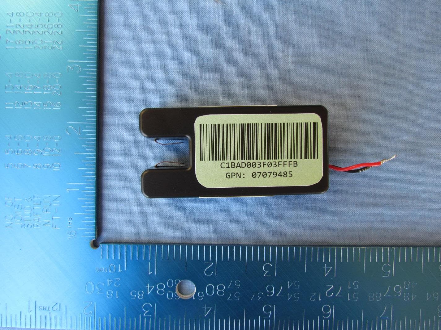
W2E-ICHIME33
Sep 23, 2015Wireless sensor for temperature monitoring
Equipment Class
DTS - Digital Transmission System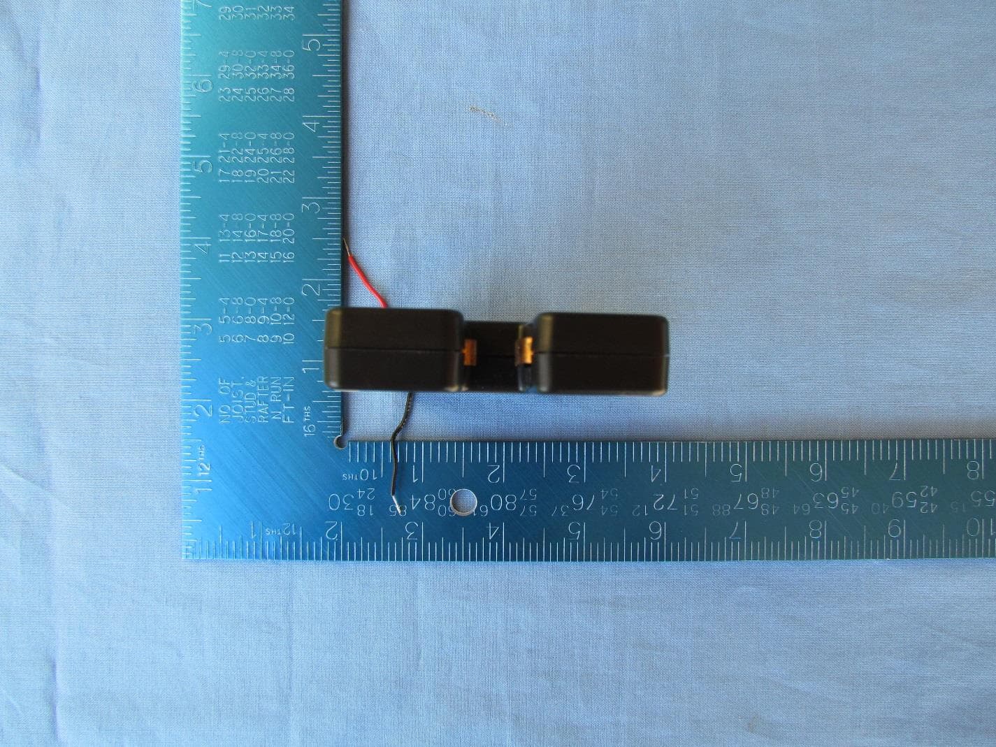
W2E-ITAGV33
Aug 27, 2015GPS tracking device with 802.15.4 Radio and 3G cell modem
Equipment Class
DTS - Digital Transmission System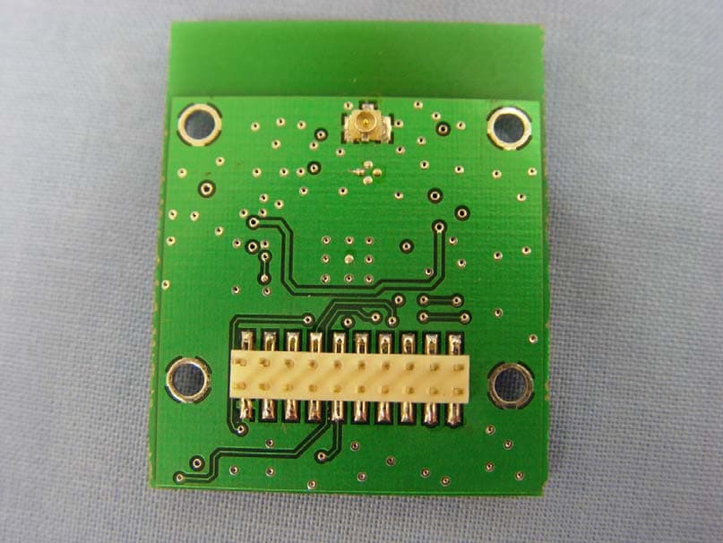
W2E-ICHIMEV20
Jan 24, 2010Wireless radio module using 802.15.4
Equipment Class
DTS - Digital Transmission System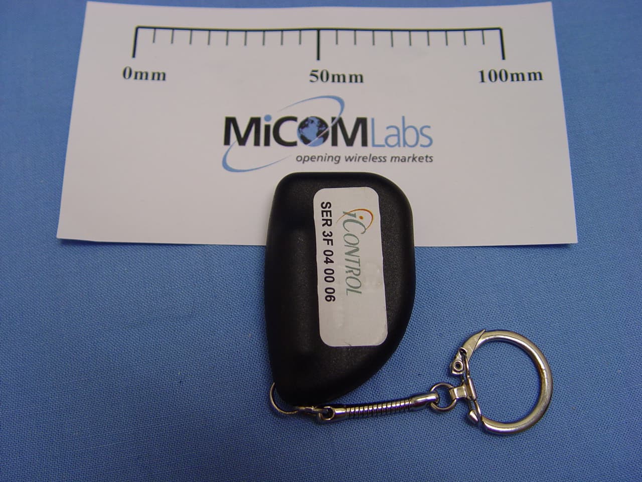
W2E-MIKEYV13
Dec 16, 2009Wireless keychain device for lock operation
Equipment Class
DTS - Digital Transmission System