W5MTOBIIC12BTablet Communication Device
Tobii AB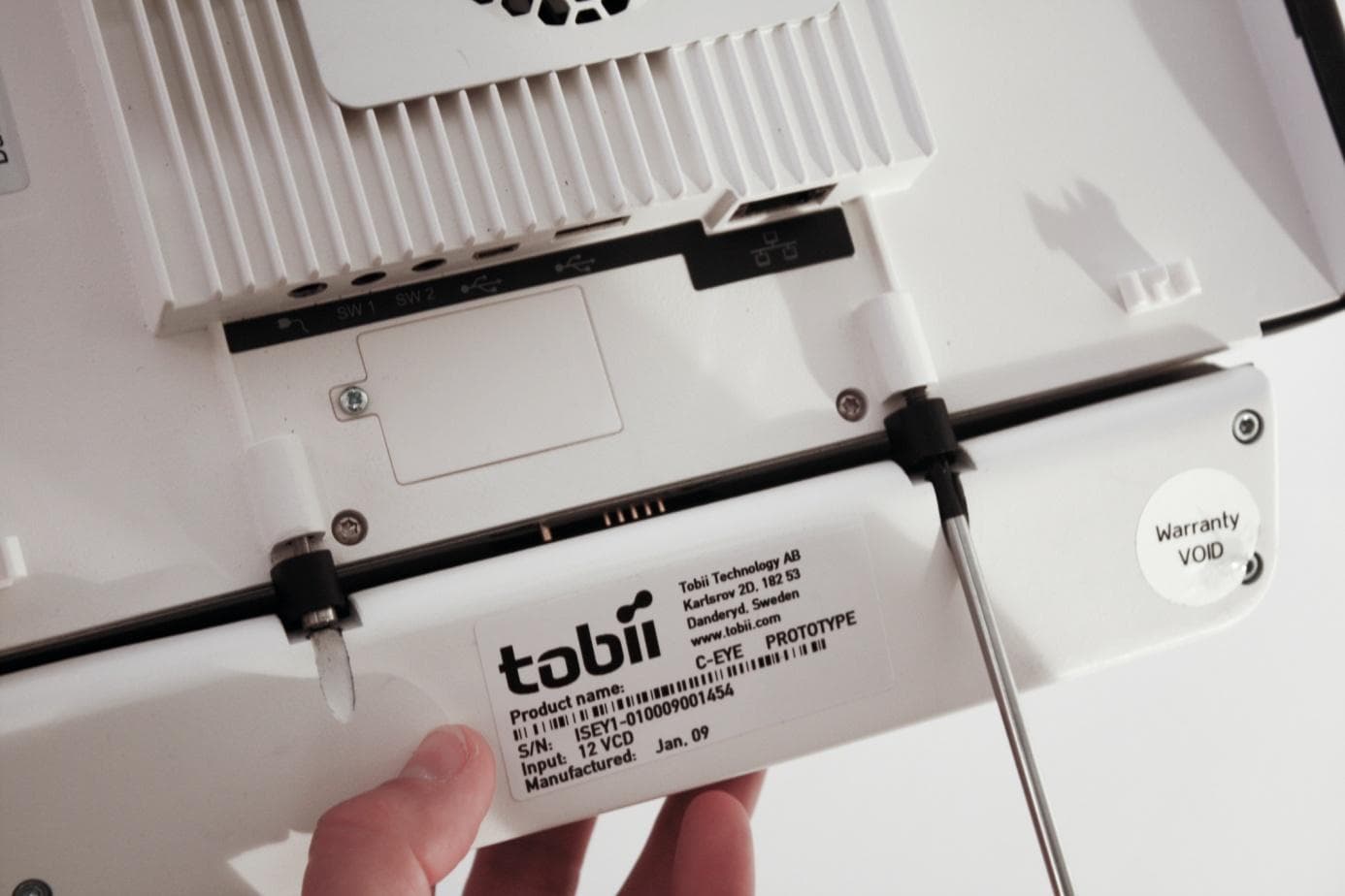
Click to zoom
Application Details
- Equipment Class
- DTS - Digital Transmission System
- Date of Grant
- Aug 16, 2012
- Application Purpose
- Original Equipment
- Date of Application
- Aug 15, 2012
- Equipment Note
- Tablet Communication Device
- Frequency Range
- 2412.00000000 - 2462.00000000
- Company
- Tobii AB
- Country
- Sweden
Documents & Files
Document Text
Text extracted from the exhibit documents filed with the FCC. Open a document above to read the original.
Users Manual
User’s Manual Tobii C-Series C8 C12 C15 CEye Celebrating Communication Tobii C-Series User’s Manual Tobii C-Series User’s Manual Content subject to change without notice. Please check Tobii web site www.tobii.com for updated versions of this manual. Manual Version 2.4 02/2012 All rights reserved. © Tobii Technology AB The information contained in this document is proprietary to Tobii Technology. Any reproduction in part or whole without prior written authoriztion by Tobii Technology is prohibited. US Patent 7, 572,008 (applies to Tobii CEye) Tobii_manual_Cseries_V2_4_02022012_UsEng Contents Introduction 6 1.1 Intended Use 6 1.2 Package Contents 7 1.3 Customer Support 7 1.4 Warranty 7 Safety 8 2.1 Avoiding Hearing Damage 8 2.2 Mounting Warning 9 2.3 Emergency Warning 9 2.4 Infrared Warning 9 2.5 Epilepsy Warning 10 2.6 Child Safety 10 Overview of the Tobii C8, C12 and C15 11 3.1 Key Features 11 3.2 Product Layout 11 3.2.1 The Tobii C8, Tobii C12 and Tobii C15 11 3.2.2 Ports, Sensors and Device Buttons 12 3.3 Preinstalled Software 13 3.4 Configuring the Device 13 Batteries in the Tobii C-Series 14 4.1 Batteries 14 4.1.1 Hot Swappable 14 4.2 Charging 14 4.2.1 Checking Charge Level 15 4.3 Inserting and Releasing the Batteries 16 Using the Tobii C-Series 18 5.1 Starting the Device 18 5.1.1 Password Information 18 5.1.2 C-Series Welcome Guide 19 5.1.3 C-Series Welcome Center 20 5.1.4 C-Series Update Notifier 21 5.2 Shutting Down the Device 23 5.3 Configuring a Switch to Power On or Off 24 5.3.1 Configuring a Switch to Power On 24 5.3.2 Configuring a Switch to Power Off 24 1 2 3 4 5 5.4 Safety Settings: C-Series Hardware Options 25 5.4.1 Audio Safety 25 5.4.2 Temperature Control Safety 26 5.4.3 Saving Changes for Future Sessions 27 5.4.4 Disabling Safety Page as Default Page on Startup 27 5.5 Adapting the Touch Screen for the User 28 5.5.1 Calibrating the Touch Screen 28 5.6 Adjusting the Backlight 30 5.6.1 Adjusting the Sound 31 5.7 Using Headphones 32 5.8 Using Bluetooth® (optional) 32 5.8.1 Handling Licenses 32 5.8.2 Enabling and Disabling Bluetooth® Communication 32 5.8.3 Connecting to a Bluetooth® Device 33 5.9 Using the WLAN (optional) 33 5.9.1 Handling Licenses 33 5.9.2 Enabling and Disabling the WLAN Communication 33 5.9.3 Connecting to a WLAN 34 5.10 Using the Camera 34 5.11 Using the Mobile Phone (optional) 35 5.11.1 Handling Licenses 35 5.11.2 Enabling and Disabling the Mobile Phone 36 5.12 Using Environmental Control (optional) 36 5.12.1 Handling Licenses 37 5.12.2 Enabling and Disabling Tira 37 5.13 Creating Shortcuts to Actions 38 5.13.1 Available Actions 38 5.13.2 Selecting Actions 39 5.14 Handling Licenses 41 5.15 System Information 42 5.16 Performing Backup and Restore 43 5.16.1 User Profile Card 43 5.16.2 Restoring Backup Files by the User 43 5.16.3 Restoring the Factory Settings of a C-Series Device: 43 Tobii CEye Module & Eye Control 45 6.1 Installing the Tobii CEye Module 45 6.1.1 Mounting the CEye Module to the Tobii C12 or C15 45 6.1.2 Required Software 46 6.1.3 Installation of Eye Control Software from USB Stick 47 6.2 Using the Tobii CEye Module 48 6.2.1 Positioning 48 6.2.2 Track Status Viewer 48 6.2.3 Track Box 49 6 6.2.4 Accessing the Tobii Eye Control Options 50 6.2.5 Creating a New Profile 51 6.2.6 Selecting Current User Profile 51 6.2.7 Deleting a Profile 52 6.2.8 Customizing the Interaction 52 6.2.9 Customizing the Calibration 54 6.2.10 Customizing the Calibration Area 56 6.2.11 Showing Track Status 57 6.2.12 Calibrating 58 6.2.13 Interrupting Calibration 58 6.2.14 Customizing Active Eye 58 6.2.15 Improving Calibration Point(s) 59 6.2.16 Removing Calibration Point(s) 60 6.2.17 Customizing Windows Control 61 6.2.18 Starting and Disabling Windows Control 63 6.2.19 Placing the Windows Control Menu 63 6.2.20 Clicking with Windows Control 64 6.2.21 Magnifying with Windows Control 64 6.2.22 Selecting Windows Control Functions 64 6.2.23 Pausing Windows Control 64 6.2.24 Scrolling with Windows Control 65 Product Care 66 7.1 Temperature & Humidity 66 7.1.1 General Use 66 7.1.2 Transportation and Storage 66 7.2 Changing the Side Covers 66 7.3 Cleaning 67 7.3.1 Cleaning of the Speaker Mesh 68 7.4 Placement 68 7.5 Transporting the C-Series Device 69 7.6 Disposing of the Batteries 69 7.7 Disposing of the C-Series Device 69 Appendices 70 8.1 Appendix A: Training Resources 70 8.2 Appendix B: CEye - Software License 70 8.3 Appendix C: Compliance Information 70 8.3.1 FCC Statment 70 8.3.2 Radio Wave Exposure and Specific Absorption Rate (SAR) Information 71 8.3.3 Industry Canada Statement 76 8.4 Appendix D: Technical Specifications 77 8.5 Appendix E: Approved Accessories 78 7 8 6 Tobii C-Series User’s Manual Thank you for purchasing a Tobii C-Series device from Tobii Technology! To ensure the optimal performance of this product, please take the time to read this manual carefully. The C-Series device is available in three different sizes: the Tobii C8 with an 8.4” screen, the Tobii C12 with a 12.1” screen and the Tobii C15 with a 15.0” screen. The Tobii C12 and C15 can be used with the Tobii CEye, to enable eye control of the device. This User’s Manual covers: • The C-Series device, models Tobii C8, Tobii C12 and Tobii C15. • The C-Series Hardware Options program (for controlling the device and licenses). • Tobii CEye (eye tracking module including Windows Control). Tobii CEye is optional equipment and is only used with the Tobii C12 and C15. 1.1 Intended Use A variety of communication methods allow Tobii C-Series users the ability to achieve their full potential. A user can communicate via text or symbols to generate synthesized (computer voice) or digitized (recorded voice) speech for face-to-face communication. A user also has the option of communication through e-mail, text messages and chat. With the Tobii C-Series, users also have the freedom and flexibility to write and edit documents, surf the Internet, play music and games, control a TV, DVD and other household appliances…
Text truncated - open the document above for the full version.
Users Manual
31 Tobii C-Series User’s Manual 5.6.1 Adjusting the Sound You can configure the built-in speakers using the Windows 7 Control Panel > Hardware and Sound and the C-Series Hardware Options. Refer to Microsoft’s information on how to configure the sound in the Windows 7 Control Panel. To configure the sound in C-Series Hardware Options: 1. Open the C-Series Hardware Options > Audio. 2. Click one of the options below Speaker output. The two audio channels, Left and Right, provide two levels of audio output. For example, the Left Channel may output the auditory scanning cues to the user’s headphones, while the Right Channel could output the chosen text to the speakers of the device, to be spoken aloud. Please note that the Left and Right Channel do not refer to left and right speakers. Either channel can output sound/audio to both of the speakers. Chapter 5 Using the Tobii C-Series 32 Tobii C-Series User’s Manual 5.7 Using Headphones If you want to enable the use of headphones: 1. Open the C-Series Hardware Options > Audio. 2. Select the Enable headphones check box. If you want to disable the use of headphones: 1. Open the C-Series Hardware Options > Audio. 2. Click to clear the Enable headphones check box. 5.8 Using Bluetooth® (optional) The built-in Bluetooth® enables connection to wireless devices which comply with ordinary Bluetooth® standards. 5.8.1 Handling Licenses To use Bluetooth® communication in the device, a license is required. To view or enter a license, go to the Licenses section in the C-Series Hardware Options. 5.8.2 Enabling and Disabling Bluetooth® Communication You enable and disable Bluetooth® communication in the Wireless section in the C-Series Hardware Options. To enable Bluetooth® communication: 1. Select the Enable wireless units check box. 2. Select the Bluetooth check box. Chapter 5 Using the Tobii C-Series 33 Tobii C-Series User’s Manual To disable Bluetooth® communication: • Clear the Bluetooth check box or the Enable wireless units check box for disabling all wireless units. If the Bluetooth® communication is activated you can see the Bluetooth icon in the Notification area on the desktop. Notification Area 5.8.3 Connecting to a Bluetooth® Device When the Bluetooth communication is activated (see above) you can connect the C-Series device to another Bluetooth® device. To search for available Bluetooth® devices and connect to them, use the Bluetooth Devices in Windows 7. To access Bluetooth Devices: • Double-click on the Bluetooth icon, , in the Notification area. 5.9 Using the WLAN (optional) The built-in WLAN (Wireless Local Area Network) support enables connection to a wireless network in compliance with the standard 802.11 b/g for the C8 and C12 and 802.11 b/g/n for the C15. 5.9.1 Handling Licenses To be able to use WLAN communication, a license is required. To view or enter a license, go to the Licenses section in the C-Series Hardware Options. 5.9.2 Enabling and Disabling the WLAN Communication You can enable and disable WLAN communication in the Wireless section in the C-Series Hardware Options. Chapter 5 Using the Tobii C-Series 34 Tobii C-Series User’s Manual To enable WLAN communication: 1. Select the Enable wireless units check box. 2. Select the WLAN check box. To disable WLAN communication: • Clear the WLAN check box or clear the Enable wireless units check box for disabling all wireless units. 5.9.3 Connecting to a WLAN To enable WLAN communication: 1. Click on the WLAN icon, , in the Notification area on the Desktop. 2. Select Connect to a network. 3. Select a network to connect to. A wireless access point which supports antenna diversity is recommended when setting up a wireless network to use with a C-Series device, for reliable performance. Such access points are generally recognized by having two antennas on the router device. Using an antivirus program is strongly recommended. 5.10 Using the Camera The built-in camera allows you to take snapshots of items in front of the C-Series device. On the Tobii C8, the camera is located on the top of the device. Chapter 5 Using the Tobii C-Series 35 Tobii C-Series User’s Manual On the Tobii C12 and Tobii C15, it is located on the back of the device. Refer to Tobii Communicator or alternative communication software manuals for camera function utilization. 5.11 Using the Mobile Phone (optional) To use the built-in Mobile phone communication feature you need a valid SIM card from a network operator in your area. The SIM card should be installed beneath the SIM card cover on the back of the C-Series device. The Mobile phone feature can be used to: • Send and receive text messages (SMS) and multimedia message (MMS) • Make telephone calls through synthetic voice • Answer telephone calls through synthetic voice 5.11.1 Handling Licenses To be able to use Mobile phone communication, a license is required. To view or enter a license, go to the Licenses section in the C-Series Hardware Options. Chapter 5 Using the Tobii C-Series 36 Tobii C-Series User’s Manual 5.11.2 Enabling and Disabling the Mobile Phone You can enable and disable Mobile phone communication in the Wireless section in the C-Series Hardware Options. To enable Mobile phone communication: 1. Select the Enable wireless units check box. 2. Select the Mobile Phone check box. To disable Mobile phone communication: • Clear the Mobile Phone check box or clear the Enable wireless units check box for disabling all wireless units. The SIM card must not have a security code enabled to be used with a C-Series device. 5.12 Using Environmental Control (optional) The C-Series device includes an environmental control unit, Tira-2.1. The Tira is a programmable infrared device that can be used to control equipment with IR remote controllers such as TV-sets or DVDs. Refer to Tobii Communicator or alternative communication software manuals on how to connect, configure and use IR remote controls. Chapter 5 Using the Tobii C-Series 37 Tobii C-Series User’s Manual Tira-2.…
Text truncated - open the document above for the full version.
Cover Letter(s)
RFI Global Services Ltd Pavilion A, Ashwood Park, Ashwood Way, Basingstoke, Hampshire, RG23 8BG Tel: +44 (0) 1256 312000 Fax: +44 (0) 1256 312001 Email: [email protected] Website: www.rfi-global.com Registered in England and Wales Company number: 2117901 FCC ID: W5MTOBIIC12B This is to confirm that the following module test reports are used in this application to support the overall C12 product compliance. Report Number 2-20722858c/07-C1 – FCC Part 22/ 24 - GSM Module Report Number RF970425L14 – FCC Part 15.247 – WIFI Module Report Number RF941229L01 – FCC 15.247 – BT Module Further testing was also performed on the C12 host equipment as the C12 uses different antennas to those tested with the modules. All these associated test reports are included in this application, together with Part 15B reports for the C12 idle mode of operation. RFI Global Services Ltd
External Photos
Tobii C12 external photos Front view with CEye mounted Angled front view Angled top/front view Top view Back view with batteries mounted Back view with CEye being mounted
ID Label/Location Info
C12 Type Label Mat 1: #50 White PET sticker (0.05mm thickness) Color: 1C Size: 139.6x47.3 with 90x47.3 glue #25 Transparent mylar sticker on right 0889 0682
Internal Photos
Internal photos Cover off view LCD Top view LCD Bottom view WLAN module Top view WLAN Module (without cover) Bottom view WLAN Module (with cover) Bottom view WLAN antenna Top view WLAN antenna Bottom view GSM module Top view GSM module Bottom view GSM antenna Top view GSM antenna Bottom view Power board (without GSM module) Top view Power board (without GSM module) Top view Power board Bottom view Bluetooth module Top view Bluetooth module Bottom view Bluetooth antenna Tira/Bluetooth board (without Bluetooth module) Top view Tira/Bluetooth board (with Bluetooth module) Top view Tira/Bluetooth board Bottom view Main board Top view Main board Bottom view Side button board Top view Side button board Bottom view Touch controller board Top view Touch controller board Bottom view USB and Headphone board Top view USB and Headphone board Bottom view Audio amplifier board Top view Audio amplifier board Bottom view User camera board Top view User camera board Bottom view LAN section board Top view LAN section board Bottom view Extension connector board Top view Extension connector board Bottom view Fan connector board Top view Fan Connector board Bottom view Hard drive Top view Hard drive Bottom view Backlight inverter board Top view Backlight inverter board Bottom view Microphone light LED board Top View Microphone light LED board Bottom view Rear connector board Top view Rear connector board Bottom view LED board Top view LED board Bottom view Left battery connector board Top view Left battery connector board Bottom view Right battery connector board Top view Right battery connector board Bottom view
Test Report
Test report No.1116509-1 Page2 (13 ) CONTENTS Page 1. Client information.................................................................................................................3 2. Equipment under test (EUT)................................................................................................3 2.1 Identification of the EUT..............................................................................................3 2.2 Additional information about the EUT.........................................................................3 2.3 Peripheral equipment.................................................................................................. 3 3. Test specifications................................................................................................................4 3.1 Standards....................................................................................................................4 3.2 Additions, deviations and exclusions from standards and accreditation....................4 3.3 Mode of operation during the test...............................................................................4 3.4 Compliance.................................................................................................................4 3.4 Test site.......................................................................................................................5 3.5 Test equipment...........................................................................................................5 4. Test summary........................................................................................................................6 5. Tables and diagrams.............................................................................................................7 6. Photos................................................................................................................................. 10 7. Intertek Semko EMC Center measurement uncertainties...................................................13 Test report No.1116509-1 Page3 (13 ) 1.CLIENT INFORMATION The EUT has been tested by request of Company:Tobii Technology AB Karlsrovägen 2D 18253 Danderyd Sweden Name of contact:Håkan Englund 2.EQUIPMENT UNDER TEST(EUT) 2.1 Identification of the EUT Equipment:Tablet PC witheye tracking device Type/Model:T -C12-R1.0A-V1 Serial number:MTC12-040100832036 Manufacturer:Tobii Technology AB Highestclock rate used:800 MHz Rating: Class: 100-240 VAC, 50/60 Hz II 2.2 Additional information about the EUT The EUT was tested ina table top configuration. The EUT consists of the followingunits: UnitsTypeSerial number Tablet PCT -C12-R1.0A-V1MTC12-030111810145 Eye tracking deviceCEyeISEY1-010100728284 AC/DCSupplyPowerbox EXM 80 5121101201592/FC:11 The EUT was tested with the following cables: CableTypeLength Mains powerTwo-core1.5 m LAN cableShielded> 3.0 m Headphone cableUnshielded1.0 m Keyboard USB cableUnshielded2.0 m 2.3 Peripheral equipment Peripheral equipment is defined as equipment needed for correct operation of the EUT, but not included as part of the EUT. EquipmentModel/TypeSerial number KeyboardHewlett-PackardsKU-0316- HeadphonesKoss portapro- RouterD-LinkDI-524DY07365002028 Test report No.1116509-1 Page4 (13 ) 3.TEST SPECIFICATIONS 3.1 Standards Requirements: CFR 47: Telecommunication, Chapter I– FCC Part 15- Radio Frequency Devices– Subpart B: Unintentional radiators (2009). Test methods: ANSI C.63.4-2003. American National Standard for Methods of Measurement of Radio-Noise Emissions from Low-Voltage Electrical and Electronic Equipment in the Range of 9 kHz to 40 GHz. 3.2 Additions, deviations and exclusions from standards and accreditation No additions, deviations or exclusions have been made from standard and accreditation. 3.3 Mode of operation during the test The EUT was supplied with 120 V AC,60 Hz. The EUT wascontinuously tracking after eyes during the tests. The LANportwasconnected and terminated to anexternalrouter. The USB port was connected to a keyboard and the audio port to headphones as described in clause 2.3. 3.4 Compliance Purpose of test: To determine whether the Equipment Under Test (EUT) fulfils the EMC requirements of FCC 15 subpart B for ClassB equipment. Limits for conducted emission, ClassB equipment: Frequency rangeQuasi PeakAverage 0.15– 0.50 MHz66 to 56dBμV*56 to 46dBμV* 0.50– 5 MHz56dBμV46 dBμV 5 – 30MHz60dBμV50 dBμV * Decreases with the logarithm of the frequency. Limits for radiated emission, ClassB at 3 m distance. Frequency rangeQuasi Peak 30–88 MHz40.0dBμV/m 88– 216 MHz43.5 dBμV/m 216– 960 MHz46.0dBμV/m 960– 1000 MHz54.0dBμV/m PeakAverage 1,0– 6,0 GHz74.0dBμV/m54.0dBμV/m Test report No.1116509-1 Page5 (13 ) 3.4Test site Measurements were performed at: Intertek Semko AB. Torshamnsgatan 43, P.O. Box 1103 SE-164 22 Kista Intertek Semko AB is a FCC listed test site with site registration number 90913. Intertek Semko AB is also accredited by Swedac and acknowledged by FCC as a CAB for measuring devices subject to Declaration of Conformity (DOC) under Parts 15 & 18. 3. 5 Test equipment Testequipment that was used during conductedemission: EquipmentManufacturerModelInventory nr. LISNRohde&SchwarzESH3-Z52727 LISNRohde&SchwarzESH3-Z58768 Measurement receiverRohde&SchwarzESCI12741 Cable-Coax9883 The measuring test equipment that was used during radiated emission: EquipmentManufacturerModelInventory nr. Measurement receiverRohde&SchwarzESU12866 Measurement receiverRohde&SchwarzESCI12798 Measurement receiverRohde&SchwarzESU13178 Integrated measurement systemRohde&SchwarzIMS12800 Pre-amplifierHewlett-Packard8449B6685 Pre-amplifierHewlett-PackardOPT H647992/7993 AntennaChaseCBL 6111A8578 AntennaRohde&SchwarzHL56230711 Biconical antennaEMCO31103006 CableHuber+SuhnerRG 2149506 CableHuber+SuhnerSucoflex 104PB40035 CableHuber+SuhnerSucoflex 104PB9755 Test report No.1116509-1 Page6 (13 ) 4.TEST SUMMARY The test has been carriedout at the Intertek S…
Text truncated - open the document above for the full version.
Test Report
Report No.: RF970425L14 1 Report Format Version 2.1.1 FCC TEST REPORT REPORT NO.: RF970425L14 MODEL NO.: LR802UKN RECEIVED: Apr. 25, 2008 TESTED: May 07 ~ Jun. 26, 2008 ISSUED: Jun. 30, 2008 APPLICANT: Qcom Technology Inc. ADDRESS: 7F, No.178, Ming Chuan E. Rd. Sec 3, Taipei, Taiwan, R.O.C. ISSUED BY: Advance Data Technology Corporation LAB ADDRESS: No.47, 14 th Ling, Chia Pau Tsuen, Linko Hsiang 244, Taipei Hsien, Taiwan, R.O.C. TEST LOCATION: No. 19, Hwa Ya 2 nd Rd, Wen Hwa Tsuen, Kwei Shan Hsiang, Taoyuan Hsien 333, Taiwan, R.O.C. This test report consists of 94 pages in total. It may be duplicated completely for legal use with the approval of the applicant. It should not be reproduced except in full, without the written approval of our laboratory. The client should not use it to claim product endorsement by TAF, A2LA or any government agencies. The test results in the report only apply to the tested sample. Report No.: RF970425L14 2 Report Format Version 2.1.1 TABLE OF CONTENTS 1. CERTIFICATION........................................................................................................... 4 2. SUMMARY OF TEST RESULTS .................................................................................. 5 2.1 MEASUREMENT UNCERTAINTY................................................................................ 5 3. GENERAL INFORMATION ........................................................................................... 6 3.1 GENERAL DESCRIPTION OF EUT ............................................................................. 6 3.2 DESCRIPTION OF TEST MODES ............................................................................... 7 3.2.1 CONFIGURATION OF SYSTEM UNDER TEST .......................................................... 7 3.2.2 TEST MODE APPLICABILITY AND TESTED CHANNEL DETAIL ............................... 8 3.3 GENERAL DESCRIPTION OF APPLIED STANDARDS ............................................ 10 3.4 DESCRIPTION OF SUPPORT UNITS ....................................................................... 10 4. TEST TYPES AND RESULTS .................................................................................... 11 4.1 RADIATED EMISSION MEASUREMENT .................................................................. 11 4.1.1 LIMITS OF RADIATED EMISSION MEASUREMENT................................................ 11 4.1.2 TEST INSTRUMENTS................................................................................................ 12 4.1.3 TEST PROCEDURES ................................................................................................ 13 4.1.4 DEVIATION FROM TEST STANDARD....................................................................... 13 4.1.5 TEST SETUP.............................................................................................................. 14 4.1.6 EUT OPERATING CONDITIONS ............................................................................... 14 4.1.7 TEST RESULTS ......................................................................................................... 15 4.2 CONDUCTED EMISSION MEASUREMENT ............................................................. 41 4.2.1 LIMITS OF CONDUCTED EMISSION MEASUREMENT........................................... 41 4.2.2 TEST INSTRUMENTS................................................................................................ 41 4.2.3 TEST PROCEDURES ................................................................................................ 42 4.2.4 DEVIATION FROM TEST STANDARD....................................................................... 42 4.2.5 TEST SETUP.............................................................................................................. 43 4.2.6 EUT OPERATING CONDITIONS ............................................................................... 43 4.2.7 TEST RESULTS ......................................................................................................... 44 4.3 6dB BANDWIDTH MEASUREMENT.......................................................................... 46 4.3.1 LIMITS OF 6dB BANDWIDTH MEASUREMENT ....................................................... 46 4.3.2 TEST INSTRUMENTS................................................................................................ 46 4.3.3 TEST PROCEDURE................................................................................................... 46 4.3.4 DEVIATION FROM TEST STANDARD....................................................................... 46 4.3.5 TEST SETUP.............................................................................................................. 47 4.3.6 EUT OPERATING CONDITIONS ............................................................................... 47 4.3.7 TEST RESULTS ......................................................................................................... 48 4.4 MAXIMUM PEAK OUTPUT POWER.......................................................................... 56 4.4.1 LIMITS OF MAXIMUM PEAK OUTPUT POWER MEASUREMENT .......................... 56 4.4.2 INSTRUMENTS .......................................................................................................... 56 4.4.3 TEST PROCEDURES ................................................................................................ 56 4.4.4 DEVIATION FROM TEST STANDARD....................................................................... 57 4.4.5 TEST SETUP.............................................................................................................. 57 4.4.6 EUT OPERATING CONDITIONS ............................................................................... 57 Report No.: RF970425L14 3 Report Format Version 2.1.1 4.4.7 TEST RESULTS ......................................................................................................... 58 4.5 POWER SPECTRAL DENSITY MEASUREMENT ...............…
Text truncated - open the document above for the full version.
Test Report
TEST REPORT FROM RFI GLOBAL SERVICES LTD Test of: Tablet PC T-C12-R1.0A-V1 C12 FCC ID: W5MTOBIIC12B IC Certification Number: 8099A-TOBIIC12B To: FCC Parts 15.247(b)(3), 15.247(d), 15.209(a) Industry Canada RSS-Gen 4.8, RSS-210 A8.4(4), RSS-Gen 4.9 & RSS-210 A8.5 Test Report Serial No.: RFI-RPT-RP80826JD10A This Test Report Is Issued Under The Authority Of John Newell, Group Quality Manager: Checked By: Sarah Williams Signature: Date of Issue: 11 July 2012 This report is issued in Adobe Acrobat portable document format (PDF). It is only a valid copy of the report if it is being viewed in PDF format with the following security options not allowed: Changing the document, Selecting text and graphics, Adding or changing notes and form fields. This report may not be reproduced other than in full, except with the prior written approval of RFI Global Services Ltd. The results in this report apply only to the sample(s) tested. TEST REPORT SERIAL NO: RFI-RPT-RP80826JD10A VERSION 1.0 ISSUE DATE: 11 JULY 2012 Page 2 of 27 RFI Global Services Ltd This page has been left intentionally blank. TEST REPORT SERIAL NO: RFI-RPT-RP80826JD10A VERSION 1.0 ISSUE DATE: 11 JULY 2012 RFI Global Services Ltd Page 3 of 27 Table of Contents 1. Customer Information .................................................................................................................. 4 2. Summary of Testing ..................................................................................................................... 5 2.1. General Information 5 2.2. Summary of Test Results 5 2.3. Methods and Procedures 6 2.4. Deviations from the Test Specification 6 3. Equipment Under Test (EUT) ....................................................................................................... 7 3.1. Identification of Equipment Under Test (EUT) 7 3.2. Description of EUT 7 3.3. Modifications Incorporated in the EUT 7 3.4. Additional Information Related to Testing 8 3.5. Support Equipment 8 4. Operation and Monitoring of the EUT during Testing ............................................................... 9 4.1. Operating Modes 9 4.2. Configuration and Peripherals 9 5. Measurements, Examinations and Derived Results ................................................................ 10 5.1. General Comments 10 5.2. Test Results 11 5.2.1. Transmitter Maximum Peak Output Power 11 5.2.2. Transmitter Radiated Emissions 20 6. Measurement Uncertainty .......................................................................................................... 26 Appendix 1. Test Equipment Used ................................................................................................ 27 TEST REPORT SERIAL NO: RFI-RPT-RP80826JD10A VERSION 1.0 ISSUE DATE: 11 JULY 2012 Page 4 of 27 RFI Global Services Ltd 1. Customer Information Company Name: Tobii Technology AB Address: Karlsrovägen 2D 7th floor Danderyd 182 53 Sweden TEST REPORT SERIAL NO: RFI-RPT-RP80826JD10A VERSION 1.0 ISSUE DATE: 11 JULY 2012 RFI Global Services Ltd Page 5 of 27 2. Summary of Testing 2.1. General Information Specification Reference: 47CFR15.247 Specification Title: Code of Federal Regulations Volume 47 (Tele…
Text truncated - open the document above for the full version.
Contact Information
Applicant
Marten Skogo(Manager)
Technical Contact
Non-Technical Contact
Tobii Technology ABGunnar Troili
[email protected]46-86636990
Test Firm
UL VS LtdDarren Rust
Technical Specifications
| # | Rule Parts | Frequency Range | Power Output |
|---|---|---|---|
| 1 | 15C | 2.41 GHz - 2.46 GHz | 13.00 mW |
Other Applications from Tobii AB
W5M-TDI12A
May 06, 2015Tobii Dynavox I-12+
Equipment Class
DSS - Part 15 Spread Spectrum Transmitter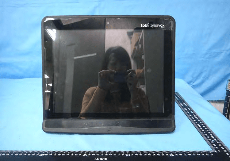
W5M-TDI15A
Apr 27, 2015Tobii Dynavox I-15+
Equipment Class
DTS - Digital Transmission System
W5M-DMSSE07
Feb 24, 2015DMS-SE07
Equipment Class
DTS - Digital Transmission System
W5M-TOBIII12A
Jun 18, 2013Rugged tablet PC with 12.1 inch screen and an optional eyetracking module integrated
Equipment Class
DSS - Part 15 Spread Spectrum Transmitter
W5M-TOBIII15A
Jun 17, 2013Rugged tablet PC with 15 inch screen and an optional eyetracking module integrated
Equipment Class
DTS - Digital Transmission System