W9B15030205BField Sensor, Gen 3
Smartfield, Inc.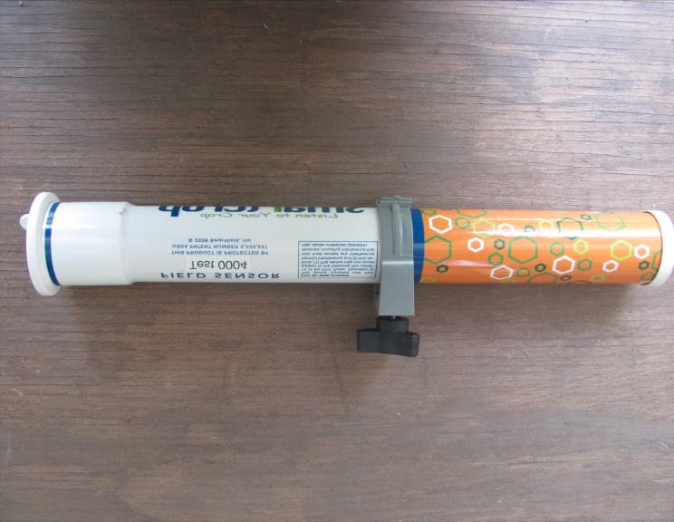
Click to zoom
Application Details
- Equipment Class
- DXX - Part 15 Low Power Communication Device Transmitter
- Date of Grant
- Dec 22, 2010
- Application Purpose
- Original Equipment
- Date of Application
- Dec 22, 2010
- Equipment Note
- Field Sensor, Gen 3
- Frequency Range
- 907.94000000 - 907.94000000
- Company
- Smartfield, Inc.
- Country
- United States
Documents & Files
Document Text
Text extracted from the exhibit documents filed with the FCC. Open a document above to read the original.
Users Manual
1 SmartCrop Sensors Installation Guide Version 1.0 Only Smartfield¥trained and certified installers are authorized to install and maintain equipment. 2 Copyright © 2010 Smartfield TM , Inc. All rights reserved. No part of this document may be reproduced or transmitted in any form or by any means electronic or mechanical, for any purpose without the express written permission of Smartfield TM , Inc. Information in this document is subject to change without prior notice. Certain names of program products and company names used in this document might be registered trademarks or trademarks owned by other entities. SMARTFIELD, INC. 2601 SE Loop 289, Suite B Lubbock, Texas 79404 http://www.smartfield.com/ For Sales Support: 2601 SE Loop 289, Suite B Lubbock, Texas 79404 877-412-8940 [email protected] For Technical Support: mailto:[email protected] This guide is frequently updated to reflect changes in the product. The latest version can always be found at http://www.smartfield.com/ Instructions to the User This equipment has been tested and found to comply with the limits for a class B digital device, pursuant to part 15 of the FCC Rules. These limits are designed to provide reasonable protection against harmful interference in a residential installation. This equipment generates, uses and can radiate radio frequency energy and if not installed and used in accordance with the instructions, may cause harmful interference to radio communications. However, there is no guarantee that interference will not occur in a particular installation. If this equipment does cause harmful interference to radio or television reception, which can be determined by turning the equipment off and on, the user is encouraged to try to correct the interference by one or more of the following measures: x Reorient or relocate the receiving antenna. x Increase the separation between the equipment and receiver. x Connect the equipment into an outlet on a circuit different from that to which the receiver is connected. x Consult the dealer or an experienced radio/TV technician for help. In order to maintain compliance with FCC regulations, shielded cables must be used with this equipment. Operations with non-approved equipment or unshielded cables is likely to result in interference to radio and TV reception. The user is cautioned that changes and modifications made to the equipment without the approval of manufacturer could void the user’s authority to operate this equipment. Page Table of Contents Introduction 3 Guidebook Conventions 3 Important Safety Precautions 3 Contents/Tools Needed 4 Installation 4-5 Warranty 5-6 3 Introduction Congratulations, you have just purchased the SmartCrop Sensors, one of the most advanced irrigation management tools available. Listen to your crop..... It’s talking to you Your crop is telling you when it is experiencing heat stress and needs water. The SmartCrop Sensor is smart technology that uses infrared (IR) temperature sensing technology coupled with patented USDA algorithms and methodology to determine when your crop is experiencing heat stress brought on by lack of water. SmartCrop Sensor provides growers a simple “IRRIGATE / DON’T IRRIGATE” signal that can be seen on the web or even on your cell phone. In addition to irrigation signals, the SmartCrop Sensors provide temperature and other environmental data via the CropInsight.com web site. SmartCrop Sensor The SmartCrop Sensor is a long plastic tube that contains the electronics used to measure, collate, and transmit crop canopy data. At the heart of the Sensor is an industrial infrared (IR) temperature-sensing device that measures the actual temperature of the crop canopy. How it works This temperature data is collected and processed by a microprocessor in the SmartCrop Sensor. At 15-minute intervals, the microprocessor turns on the radio transmitter and sends the latest set of temperature data directly to the Base Station. The Base Station collects the crop canopy data from each Sensor. Using the crop canopy temperatures from each Sensor, along with other localized environmental measurements, the web server determines if the crop is in stress or not. This decision process is performed every 15 minutes throughout the day. The CropInsight¥ web site keeps track of how much stress is accumulating in the crop and will signal for irrigation when a minimum stress time has been reached. This stress time, along with other crop factors is easily programmed into the web site during setup and these factors can be changed remotely during the growing session. Guidebook Conventions To highlight the most important points – we have used a set of simple icons, which draw attention to key information and settings. Key: The Check Icon indicates a setting that we recommend you use or enable. The Info Icon highlights important facts and information about SmartCrop Sensors, to help you make better use of the product. The Hazard Icon highlights areas where potential problems can arise. Important Safety Precautions Only Smartfield¥trained and certified installers are authorized to install and maintain equipment; non- certified installations void equipment warranty. Important: DO NOT begin installation until all utility lines have been located and marked by your local utility company. Digging without knowing the location of utility lines can result in a damaged system, injury or death. This manual contains important information about the installation, operation and safe use of this product. This information should be given to the owner and / or operator of this equipment. Warning: Before installing this product, read and follow all warning notices and instructions, which are included. Failure to follow safety warnings and instructions can result in severe injury or property damage. 4 Contents SmartCrop Sensor 2 “AA” Battery 1 Mounting Bracket Assembly Other Materials Needed Six (6”) inside pole One (1) spade Two (2) ¾ X ½ bolts Two (2) ¾ …
Text truncated - open the document above for the full version.
Cover Letter(s)
Correspondence by Project Project Number: Correspondence Number Memo W9B15030205B-1 1) A new TCB certification contract needs to be filled out. Response: The new TCB certification contract has been filled out. 2) The test report shows that the device was tested at an angle. Please explain why it wasn’t tested in a normal axis such as X, Y or Z. Response: The manual has been revised to show placing the device at a 45 degree angle. 3) The block diagram submitted states a different frequency range. Please submit a new block diagram with the correct frequency range. Response: The block diagram has been revised to show the correct frequency. 4) Some of the values on the schematics submitted do not match what the internal photos show. Please submit new schematics. The schematics are correct. Please see the Bourns document on how certain components are labeled. Examples: R4 is 100 KOhm, CR0603 5%. On page 4 of the Bourns spec, the resistor markings for an E-24 format are: 3 digits, first two digits are significant, third digit is number of zeros. To get a marking code for 100000 Ohms, the value of 10 is followed by 4 zeros, giving a code of 104. So a Bourns CR0603 5% resistor labeled 104 translates to 100000 = 100 KOhms, matching the schematic for R4. R23 is 200 KOhm, CR0603 1%. On page 4 of the Bourns spec in the "EIA-96 Marking for CR0603, 1%" table, you can find 200 in column 6 "R Value". Immediately to the left, in the Code column, is 30. To get a marking code for 200 KOhm, the Code of 30 is followed by the letter D, which means a 10^3 multiplier. So a Bourns CR0603 1% resistor labeled 30D translates to 200x10^3 = 200000 Ohms = 200 KOhms, matching the schematic for R23. R27 is 5.9 KOhm, CR0603 1%. On page 4 of the Bourns spec in the "EIA-96 Marking for CR0603, 1%" table, you can find 590 in column 14 "R Value". Immediately to the left, in the Code column, is 75. To get a marking value of 5900 Ohms, the Code of 75 is followed by the letter B, which means a 10^1 mutiplier. So a Bourns CR0603 1% resistor labeled 75B translates to 590x10^1 = 5900 Ohms, matching the schematic for R27.
Cover Letter(s)
*RoHS Directive 2002/95/EC Jan 27 2003 including Annex Specifications are subject to change without notice. Customers should verify actual device performance in their specific applications. CR0603/CR0805/CR1206 - Chip Resistors Electrical Characteristics Characteristic Data Dimensional Drawing Derating Curve DIMENSIONS ARE: MM (INCHES) Features ■RoHS compliant* ■Power rating at 70 °C: CR0603 - 0.10 W, CR0805 - 0.125 W, CR1206 - 0.25 W ■Tight tolerances of bottom electrode width ■Suitable for all types of soldering processes ■Three layer contacting process with nickel barrier prevents leaching and provides excellent solderability ■Paper tape on reel for automatic placement Characteristic ModelModelModel CR0603CR0805CR1206 Power Rating @ 70 °C1/10 W1/8 W1/4 W Operating Temperature Range-55 °C to +155 °C Derated to 0 Load at+155 °C Maximum Working Voltage50 V150 V200 V Maximum Overload Voltage100 V300 V400 V Resistance Range: 1 %, E-96 + E-2410 ohms - 1 megohm Resistance Range: 5 %, E-24 1 ohms - 10 megohms Zero Ohm Jumper <0.01 ohms Temperature Coefficient Special value on request 1 %: ±100 ppm/°C 5 %: ±200 ppm/°C 1 ohm - 10 ohms: -200 ppm/°C to +500 ppm/°C L H I 2 I 2 W I 1 I 1 Overcoat Resistor (Ru02) (Jumper chip is a conductor) Alumina Substrate Internal Electrode (Ag-Pd) Secondary Electrode (Nickel Plated) External Electrode (see Part Numbering - may be ordered as solder-plated or tin-plated) Chip Dimensions Dimension ModelModelModel CR0603CR0805CR1206 L 1.60±0.102.00±0.153.20±0.25 (0.063±0.004)(0.079±0.006)(0.126±0.010) W 0.80±0.101.25±0.151.60±0.15 (0.031±0.004)(0.049±0.006)(0.063±0.006) H 0.45±0.100.50±0.100.60±0.15 (0.018±0.004)(0.020±0.004)(0.024±0.006) I 1 0.30±0.200.40±0.200.50±0.25 (0.012±0.008)(0.016±0.008)(0.020±0.010) I 2 0.30±0.200.40±0.200.50±0.20 (0.012±0.008)(0.016±0.008)(0.020±0.010) 3.0 2.0 1.0 0 10 100 1K 10K 100K 1M Load Life 1000Hr ∆ R/R (%) 3.0 2.0 1.0 0 10 100 1K 10K 100K 1M Moisture Load Life 1000Hr ∆ R/R (%) Resistance Value (Ω) Resistance Value (Ω) 1.0 0.5 0 -0.5 10 100 1K 10K 100K 1M Short Time Overload ∆ R/R (%) Resistance Value (Ω) 100 80 60 40 20 0 Rated power in percentage (%) -55 0 70 155 (°C) Ambient temperature *RoHS COMPLIANT For Standard Values Used in Capacitors, Inductors, and Resistors, click here. Specifications are subject to change without notice. Customers should verify actual device performance in their specific applications. Performance Characteristics (Tests According to MIL-STD-202, MIL-R-55342B, EIA RS-396) TestProcedureMethodSpecification Deviation from Nominal 1 %5 % DC Resistance—MIL-STD-202 303MIL-R-55342D 4.7.2F:≤±1 %≤±5.0 % EIA RS-396 4.4 Thermal Shock-40 °C, 60 minutes;MIL-STD-202 107MIL-R-55342D 4.7.3≤±0.5 % +0.05 Ω≤±1 % +0.05Ω +125 °C, 60 minutesEIA RS-396 4.5 Low Temperature-55 °C, 1 hour off;MIL-R-55342D 4.7.4MIL-R-55342D 4.7.4≤±0.5 % 0.05Ω≤±1.0 % +0.05Ω Operation45 minutes onEIA RS-396 4.6 Short Time Rated Voltage x 2.5; MIL-R-55342D 4.7.5MIL-R-55342D 4.7.5≤±1 % +0.05Ω≤±2.0 % +0.05Ω Overload5 secondsEIA RS-396 4.7 CR0603: 100 V max. CR0805; 300 V max. CR1206: 400 V max. High Temperature+125 °C; 1000 hoursMIL-R-55342D 4.7.6MIL-R-55342D 4.7.6≤±1.0 % +0.05Ω≤+2.0 % +0.1Ω ExposureEIA RS-396 4.8 Resistance to260 °C, 10 secondsMIL-R-55342D 4.7.7MIL-R-55342D 4.7.7≤±0.5 % +0.05Ω≤±1.0 % +0.05Ω Soldering Heat Moisture90-98 %RH; 10 cyclesMIL-STD-202 106DMIL-R-55342D 4.7.8≤±0.5 % +0.05Ω≤±2.0 % +0.05Ω ResistanceEIA RS-396 4.9 Load Life+70 °C; 1.5 hours on,MIL-STD-202 108MIL-R-55342D 4.7.10≤±1.0 % +0.05Ω≤±3.0 % +0.1Ω 1000 Hours0.5 hours off;Condition D 1000 hoursEIA RS-396 4.12 Solderability+235 °C; 3 secondsMIL-STD-202 208MIL-R-55342D 4.7.11≥95 % of area ≥95 % of area EIA RS-396 4.11coveredcovered Terminal StrengthPull TestMIL-R-55342D 4.7.12MIL-R-55342D 4.7.12≥500 g≥500 g Current NoiseQuan-Tech Model 315B MIL-STD-202 308MIL-R-55342D 6.6R≤1kΩ; max. 1 μV/VR≤1kΩ; max. 1 μV/V R≤10kΩ; max. 3 μV/VR≤10kΩ; max. 3 μV/V R≤100kΩ; max. 6 μV/VR≤100kΩ; max. 6 μV/V R≤1MΩ; max. 10 μV/VR≤2MΩ; max. 10 μV/V Humidity,+40 °C; 90-95 % RH,MIL-STD-202 103B—≤±2.5 % +0.05Ω≤±2.5 % +0.05Ω Steady State1344 HoursCondition D Salt Spray96 hoursMIL-STD-202 101D—≤±1.0 % +0.2Ω≤±1.0 % +0.1Ω Condition A Vibration10-2000 Hz, 6 hoursMIL-STD-202 201A—≤±0.5 % +0.1Ω≤±1.0 % +0.1Ω Voltage Coefficient—MIL-STD-202 309—≤100 ppm/V≤100 ppm/V InsulationTest Potential 500VMIL-STD-202 302—≥10 3 MΩ≥10 3 MΩ ResistanceCR0603: 100VCondition B Dielectric—MIL-STD-202 301—≥500 V (CR1206, CR0805) Withstanding≥300 V (CR0603) Voltage Drop Test1 mMIL-STD-202 203B—≤±0.5 % +0.1Ω≤±1.0 % +0.1Ω Bending Test5 mm/90 mm; 10 sec.——≤±1 % +0.05Ω≤±1.0 % +0.05Ω CR0603/CR0805/CR1206 - Chip Resistors Specifications are subject to change without notice. Customers should verify actual device performance in their specific applications. Soldering Profile for RoHS Compliant Chip Resistors and Arrays CR0603/CR0805/CR1206 - Chip Resistors 25 75 125 175 225 275 050100150200250300 Time (seconds) Temperature (°C) 60 - 120 seconds 60 - 90 seconds 260 °C peak 190 °C 150 °C 220 °C Ramp Down 6 °C/second 255 °C Maximum of 20 seconds between +255 °C and +260 °C Ramp Up 3 °C/second maximum 10 seconds minimum <1> <1> SeriesAB CR06031.9 ± 0.21.1 ± 0.2 (.075 ± .008)(.043 ± .008) CR08052.4 ± 0.21.65 ± 0.2 (.094 ± .008)(.065 ± .008) CR12063.57 ± 0.22.00 ± 0.2 (.161 ± .008)(.079 ± .008) Packaging Dimensions (Conforms to EIA RS-481A) Marking on reel: Part number, quantity, resistance value and tolerance, date code. 1.5 +0.1/-0 (.056 + .004/-0) Maximum 1 mm (.040) thick *Cumulative tolerance over 10 holes: ±0.2 mm 1.75 ± 0.1 (.059 ± .004) B 4.0 ± 0.1 (.157 ± .004) 2.0 ± 0.05 (.079 ± .002) A 8.0 ± 0.2 (.315 ± .008) 3.5 ± 0.05 (.138 ± .002) 4.0 ± 0.1 (.157 ± .004) 20.5 (.807) 13.0 ± 0.5 (.512 ± .020) 2.0 (.080) 1.0 ± 0.2 (.040 ± .020) 10.0 ± 1.5 (.394 ± .059) 80.0 ± 1.0 (3.150 ± .040) 178.0 ± 2.0 (7.008 ± .080) Specifications are subject to change without notice. Customers should verify actual device performance in their specific applications…
Text truncated - open the document above for the full version.
ID Label/Location Info
PLACE CLAMP HERE FIELD SENSOR THIS PRODUCT IS PROTECTED BY USDA PATENT NUMBER 5,539,637 © 2010 Smartfield, Inc FCC: W9B15030205B IC: 8980A-15030205B This device complies with Part 15 of the FCC Rules. Operation is subject to the following two conditions: (1) This device may not cause harmful interference and (2) this device must accept any interference received, including interference that may cause undesired operation. MODEL # 15030205B
Test Report
Report Number: B00507D1 FCC Part 15 Subpart B and FCC Section 15.249 Test Report Field Sensor, Gen 3 Model: 15030205B Brea Division 114 Olinda Drive Brea, CA 92823 (714) 579-0500 Agoura Division 2337 Troutdale Drive Agoura, CA 91301 (818) 597-0600 Silverado Division 19121 El Toro Road Silverado, CA 92676 (949) 589-0700 Lake Forest Division 20621 Pascal Way Lake Forest, CA 92630 (949) 587-0400 Page 1 of 16 FCC PART 15 SUBPART B and C TEST REPORT for FIELD SENSOR, GEN 3 Model: 15030205B Prepared for SMARTFIELD, INC. 2601 SE LOOP 289 LUBBOCK, TEXAS 79404 Prepared by:_____________________ KYLE FUJIMOTO Approved by:____________________ JAMES ROSS COMPATIBLE ELECTRONICS INC. 114 OLINDA DRIVE BREA, CALIFORNIA 92823 (714) 579-0500 DATE: JUNE 14, 2010 REPORT APPENDICES TOTAL BODY A B C D E PAGES 16 2 2 2 11 4 37 This report shall not be reproduced except in full, without the written approval of Compatible Electronics. Report Number: B00507D1 FCC Part 15 Subpart B and FCC Section 15.249 Test Report Field Sensor, Gen 3 Model: 15030205B Brea Division 114 Olinda Drive Brea, CA 92823 (714) 579-0500 Agoura Division 2337 Troutdale Drive Agoura, CA 91301 (818) 597-0600 Silverado Division 19121 El Toro Road Silverado, CA 92676 (949) 589-0700 Lake Forest Division 20621 Pascal Way Lake Forest, CA 92630 (949) 587-0400 Page 2 of 16 TABLE OF CONTENTS Section / Title PAGE GENERAL REPORT SUMMARY 4 SUMMARY OF TEST RESULTS 4 1. PURPOSE 5 2. ADMINISTRATIVE DATA 6 2.1 Location of Testing 6 2.2 Traceability Statement 6 2.3 Cognizant Personnel 6 2.4 Date Test Sample was Received 6 2.5 Disposition of the Test Sample 6 2.6 Abbreviations and Acronyms 6 3. APPLICABLE DOCUMENTS 7 4. DESCRIPTION OF TEST CONFIGURATION 8 4.1 Description of Test Configuration – EMI 8 4.1.1 Cable Construction and Termination 9 5. LISTS OF EUT, ACCESSORIES AND TEST EQUIPMENT 10 5.1 EUT and Accessory List 10 5.2 EMI Test Equipment 11 6. TEST SITE DESCRIPTION 12 6.1 Test Facility Description 12 6.2 EUT Mounting, Bonding and Grounding 12 6.3 Facility Environmental Characteristics 12 7. TEST PROCEDURES 13 7.1 RF Emissions 13 7.1.1 Conducted Emissions Test 13 7.1.2 Radiated Emissions (Spurious and Harmonics) Test 14 8. CONCLUSIONS 16 Report Number: B00507D1 FCC Part 15 Subpart B and FCC Section 15.249 Test Report Field Sensor, Gen 3 Model: 15030205B Brea Division 114 Olinda Drive Brea, CA 92823 (714) 579-0500 Agoura Division 2337 Troutdale Drive Agoura, CA 91301 (818) 597-0600 Silverado Division 19121 El Toro Road Silverado, CA 92676 (949) 589-0700 Lake Forest Division 20621 Pascal Way Lake Forest, CA 92630 (949) 587-0400 Page 3 of 16 LIST OF APPENDICES APPENDIX TITLE A Laboratory Recognitions B Modifications to the EUT C Additional Models Covered Under This Report D Diagram, Charts, and Photos • Test Setup Diagram • Antenna and Amplifier Factors • Radiated Emissions Photos E Data Sheets LIST OF FIGURES FIGURE TITLE 1 Conducted Emissions Test Setup 2 Plot Map And Layout of Radiated Test Site – 3 Meters Report Number: B00507D1 FCC Part 15 Subpart B and FCC Section 15.249 Test Report Field Sensor, Gen 3 Model: 15030205B Brea Division 114 Olinda Drive Brea, CA 92823 (714) 579-0500 Agoura Division 2337 Troutdale Drive Agoura, CA 91301 (818) 597-0600 Silverado Division 19121 El Toro Road Silverado, CA 92676 (949) 589-0700 Lake Forest Division 20621 Pascal Way Lake Forest, CA 92630 (949) 587-0400 Page 4 of 16 GENERAL REPORT SUMMARY Compatible Electronics Inc. generates this electromagnetic emission test report, which is an independent testing and consulting firm. The test report is based on testing performed by Compatible Electronics personnel according to the measurement procedures described in the test specifications given below and in the "Test Procedures" section of this report. The measurement data and conclusions appearing herein relate only to the sample tested and this report may not be reproduced without the written permission of Compatible Electronics, unless done so in full. This report must not be used to claim product endorsement by NVLAP, NIST or any other agency of the U.S. Government. Device Tested: Field Sensor, Gen 3 Model: 15030205B S/N: N/A Product Description: See Expository Statement Modifications: The EUT was not modified in order to meet the specifications. Customer: Smartfield, Inc. 2601 SE Loop 289 Lubbock, Texas 79424 Test Date(s): May 7, 2010 Test Specifications: EMI requirements CFR Title 47, Part 15, Subpart B Test Procedure: ANSI C63.4 Test Deviations: The test procedure was not deviated from during the testing. SUMMARY OF TEST RESULTS TEST DESCRIPTION RESULTS 1 Conducted RF Emissions 150 kHz to 30 MHz The EUT does not directly or indirectly connect to the AC mains, thus this test was not performed. 2 Radiated RF Emissions 10 kHz – 9300 MHz (Transmitter Portion) Complies with the limits of CFR Title 47, Part 15, Subpart C, sections 15.205, 15.209, and 15.249. Highest reading in relation to spec limit: 93.42 (QP) dBuV/m @ 907.94 MHz (*U = 4.22 dB) 3 Radiated RF Emissions 10 kHz – 9300 MHz (Digital Portion) Complies with the Class B limits of CFR Title 47, Part 15, Subpart B. *U = Expanded Uncertainty with a coverage factor of k=2 Report Number: B00507D1 FCC Part 15 Subpart B and FCC Section 15.249 Test Report Field Sensor, Gen 3 Model: 15030205B Brea Division 114 Olinda Drive Brea, CA 92823 (714) 579-0500 Agoura Division 2337 Troutdale Drive Agoura, CA 91301 (818) 597-0600 Silverado Division 19121 El Toro Road Silverado, CA 92676 (949) 589-0700 Lake Forest Division 20621 Pascal Way Lake Forest, CA 92630 (949) 587-0400 Page 5 of 16 1. PURPOSE This document is a qualification test report based on the Electromagnetic Interference (EMI) tests performed on the Field Sensor, Gen 3, Model: 15030205B. The EMI measurements were performed according to the measurement procedure described in ANSI C63.4. The tests were performed in order to determine whether the electromagnetic emissions from the equipment under test, referred to as EUT he…
Text truncated - open the document above for the full version.
Contact Information
Applicant
Joel Hohenberger(Chief Technology Officer)
Technical Contact
Compatible Electronics, Inc.Kyle Fujimoto
[email protected]714-579-0500
114 Olinda Drive · Brea · United States
Test Firm
Compatible Electronics, Inc.Michael Christensen
[email protected]714-579-0500
Technical Specifications
| # | Rule Parts | Frequency Range | Power Output |
|---|---|---|---|
| 1 | 15C | 907.94 MHz - 907.94 MHz | - |
Other Applications from Smartfield, Inc.
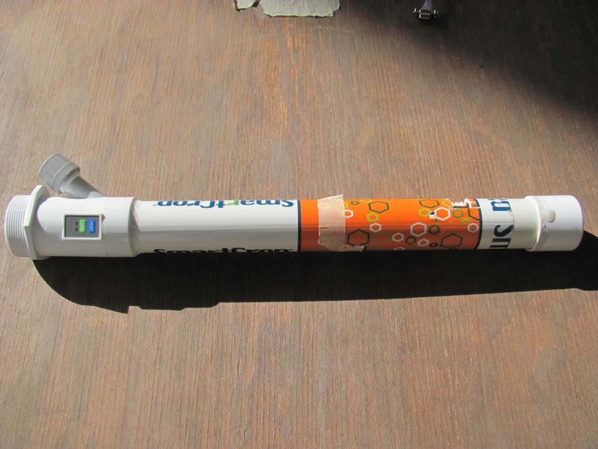
W9B15030207-A
Mar 03, 2011TallCrop
Equipment Class
DTS - Digital Transmission System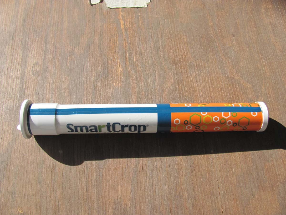
W9B15030201-A
Mar 03, 2011SmartCrop
Equipment Class
DTS - Digital Transmission System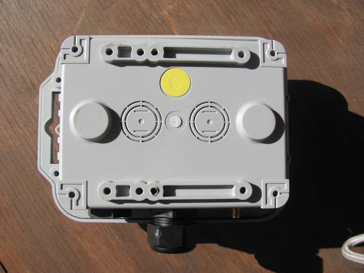
W9B15051102-A
Feb 13, 2011Smart Profile
Equipment Class
DTS - Digital Transmission System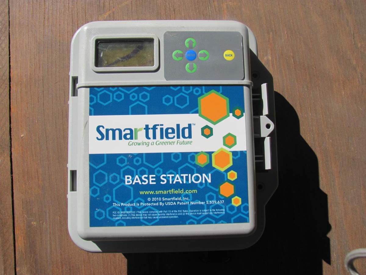
W9B15010303-A
Feb 13, 2011Base Station
Equipment Class
DTS - Digital Transmission System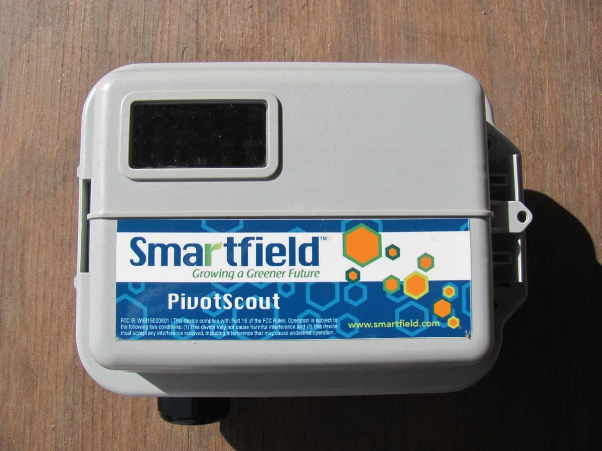
W9B15050802-A
Feb 13, 2011Pivot Scout
Equipment Class
DTS - Digital Transmission System