WAP4008Bluetooth Module
Cypress Semiconductor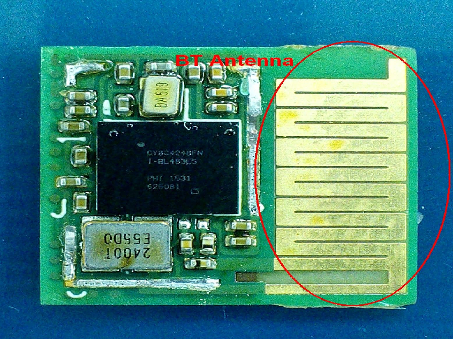
Click to zoom
Application Details
- Equipment Class
- DTS - Digital Transmission System
- Date of Grant
- Dec 10, 2015
- Application Purpose
- Original Equipment
- Date of Application
- Dec 10, 2015
- Equipment Note
- Bluetooth Module
- Frequency Range
- 2402.00000000 - 2480.00000000
- Company
- Cypress Semiconductor
- Country
- United States
Documents & Files
Document Text
Text extracted from the exhibit documents filed with the FCC. Open a document above to read the original.
Users Manual
PRELIMINARY CYBLE-014008-00 EZ-BLE TM PSoC ® Module Cypress Semiconductor Corporation198 Champion CourtSan Jose,CA 95134-1709408-943-2600 Document Number: 002-00023 Rev. *C Revised October 29, 2015 General Description The Cypress CYBLE-014008-00 is a fully certified and qualified module supporting Bluetooth Low Energy (BLE) wireless communication. The CYBLE-014008-00 is a turnkey solution and includes onboard crystal oscillators, trace antenna, passive components, and the Cypress PSoC ® 4 BLE. Refer to the PSoC ® 4 BLE datasheet for additional details on the capabilities of the PSoC ® 4 BLE device used on this module. The EZ-BLE TM PSoC ® module is a scalable and reconfigurable platform architecture. It combines programmable and reconfigurable analog and digital blocks with flexible automatic routing. The CYBLE-014008-00 also includes digital programmable logic, high-performance analog-to-digital conversion (ADC), opamps with comparator mode, and standard communication and timing peripherals. The CYBLE-014008-00 includes a royalty-free BLE stack compatible with Bluetooth 4.1 and provides up to 25 GPIOs in a small 11 × 11 × 1.80 mm package. The CYBLE-014008-00 is a complete solution and an ideal fit for applications seeking a highly integrated BLE wireless solution. Module Description nModule size: 11.0 mm × 11.0 mm × 1.80 mm (with shield) nBluetooth 4.1 single-mode module nIndustrial temperature range: –40 °C to +85 °C n32-bit processor (0.9 DMIPS/MHz) with single-cycle 32-bit multiply, operating at up to 48 MHz n128-KB flash memory n16-KB SRAM memory nWatchdog timer with dedicated internal low-speed oscillator (ILO) nTwo-pin SWD for programming nUp to 25 GPIOs configurable as open drain high/low, pull-up/pull-down, HI-Z analog, HI-Z digial, or strong output nCertified to FCC, CE, MIC, KC, and IC regulations nBluetooth SIG 4.1 qualified Power Consumption nTX output power: –18 dbm to +3 dbm nReceived signal strength indicator (RSSI) with 1-dB resolution nTX current consumption of 15.6 mA (radio only, 0 dbm) nRX current consumption of 16.4 mA (radio only) nLow power mode support pDeep Sleep: 1.3 μA with watch crystal oscillator (WCO) on pHibernate: 150 nA with SRAM retention pStop: 60 nA with XRES wakeup Programmable Analog nFour opamps with reconfigurable high-drive external and high-bandwidth internal drive, comparator modes, and ADC input buffering capability; can operate in Deep-Sleep mode. n12-bit, 1-Msps SAR ADC with differential and single-ended modes; channel sequencer with signal averaging nTwo current DACs (IDACs) for general-purpose or capacitive sensing applications on any pin nOne low-power comparator that operate in Deep-Sleep mode Programmable Digital nFour programmable logic blocks called universal digital blocks, (UDBs), each with eight macrocells and datapath nCypress-provided peripheral Component library, user-defined state machines, and Verilog input Capacitive Sensing nCypress CapSense Sigma-Delta (CSD) provides best-in-class SNR (> 5:1) and liquid tolerance nCypress-supplied software component makes capacitive-sensing design easy nAutomatic hardware-tuning algorithm (SmartSense™) Segment LCD Drive nLCD drive supported on all GPIOs (common or segment) nOperates in Deep-Sleep mode with four bits per pin memory Serial Communication nTwo independent runtime reconfigurable serial communication blocks (SCBs) with I 2 C, SPI, or UART functionality Timing and Pulse-Width Modulation nFour 16-bit timer, counter, pulse-width modulator (TCPWM) blocks nCenter-aligned, Edge, and Pseudo-random modes nComparator-based triggering of Kill signals for motor drive and other high-reliability digital logic applications Up to 25 Programmable GPIOs nAny GPIO pin can be CapSense, LCD, analog, or digital nTwo overvoltage-tolerant (OVT) pins; drive modes, strengths, and slew rates are programmable PRELIMINARY CYBLE-014008-00 Document Number: 002-00023 Rev. *CPage 2 of 40 Contents Overview............................................................................ 3 Module Description...................................................... 3 Pad Connection Interface ................................................ 5 Recommended Host PCB Layout ................................... 6 Power Supply Connections and Recommended External Components.................................................................... 10 Connection Options................................................... 10 External Component Recommendation .................... 10 Critical Components List ........................................... 13 Antenna Design......................................................... 13 Electrical Specification .................................................. 14 GPIO ......................................................................... 16 XRES......................................................................... 17 Analog Peripherals.................................................... 17 Digital Peripherals ..................................................... 21 Serial Communication ............................................... 23 Memory ..................................................................... 24 System Resources .................................................... 24 Environmental Specifications ....................................... 30 Environmental Compliance ....................................... 30 RF Certification.......................................................... 30 Environmental Conditions ......................................... 30 ESD and EMI Protection ........................................... 30 Regulatory Information.................................................. 31 FCC........................................................................... 31 Industry Canada (IC) Certification............................. 32 European R&TTE Declaration of Conformity ............ 32 MIC Japan................................................................. 33 KC…
Text truncated - open the document above for the full version.
Users Manual
PRELIMINARY CYBLE-214009-00 EZ-BLE TM PSoC ® Module Cypress Semiconductor Corporation198 Champion CourtSan Jose,CA 95134-1709408-943-2600 Document Number: 002-09714 Rev. ** Revised October 29, 2015 General Description The Cypress CYBLE-214009-00 is a fully certified and qualified module supporting Bluetooth Low Energy (BLE) wireless communication. The CYBLE-214009-00 is a turnkey solution and includes onboard crystal oscillators, trace antenna, passive components, and the Cypress PSoC ® 4 BLE. Refer to the PSoC ® 4 BLE datasheet for additional details on the capabilities of the PSoC ® 4 BLE device used on this module. The EZ-BLE TM PSoC ® module is a scalable and reconfigurable platform architecture. It combines programmable and reconfigurable analog and digital blocks with flexible automatic routing. The CYBLE-214009-00 also includes digital programmable logic, high-performance analog-to-digital conversion (ADC), opamps with comparator mode, and standard communication and timing peripherals. The CYBLE-214009-00 includes a royalty-free BLE stack compatible with Bluetooth 4.1 and provides up to 25 GPIOs in a small 11 × 11 × 1.80 mm package. The CYBLE-214009-00 is a complete solution and an ideal fit for applications seeking a highly integrated BLE wireless solution. CYBLE-214009-00 is drop-in compatible CYBLE-014008-00. Module Description nModule size: 11.0 mm × 11.0 mm × 1.80 mm (with shield) nBluetooth 4.1 single-mode module nIndustrial temperature range: –40 °C to +85 °C n32-bit processor (0.9 DMIPS/MHz) with single-cycle 32-bit multiply, operating at up to 48 MHz n256-KB flash memory, 32-KB SRAM memory nWatchdog timer with dedicated internal low-speed oscillator (ILO) nTwo-pin SWD for programming nUp to 25 GPIOs configurable as open drain high/low, pull-up/pull-down, HI-Z analog, HI-Z digial, or strong output nCertified to FCC, CE, MIC, KC, and IC regulations nBluetooth SIG 4.1 qualified Power Consumption nTX output power: –18 dbm to +3 dbm nReceived signal strength indicator (RSSI) with 1-dB resolution nTX current consumption of 15.6 mA (radio only, 0 dbm) nRX current consumption of 16.4 mA (radio only) nLow power mode support pDeep Sleep: 1.3 μA with watch crystal oscillator (WCO) on pHibernate: 150 nA with SRAM retention pStop: 60 nA with XRES wakeup Programmable Analog nFour opamps with reconfigurable high-drive external and high-bandwidth internal drive, comparator modes, and ADC input buffering capability; can operate in Deep-Sleep mode. n12-bit, 1-Msps SAR ADC with differential and single-ended modes; channel sequencer with signal averaging nTwo current DACs (IDACs) for general-purpose or capacitive sensing applications on any pin nOne low-power comparator that operate in Deep-Sleep mode Programmable Digital nFour programmable logic blocks called universal digital blocks, (UDBs), each with eight macrocells and datapath nCypress-provided peripheral Component library, user-defined state machines, and Verilog input Capacitive Sensing nCypress CapSense Sigma-Delta (CSD) provides best-in-class SNR (> 5:1) and liquid tolerance nCypress-supplied software component makes capacitive-sensing design easy nAutomatic hardware-tuning algorithm (SmartSense™) Segment LCD Drive nLCD drive supported on all GPIOs (common or segment) nOperates in Deep-Sleep mode with four bits per pin memory Serial Communication nTwo independent runtime reconfigurable serial communication blocks (SCBs) with I 2 C, SPI, or UART functionality Timing and Pulse-Width Modulation nFour 16-bit timer, counter, pulse-width modulator (TCPWM) blocks nCenter-aligned, Edge, and Pseudo-random modes nComparator-based triggering of Kill signals for motor drive and other high-reliability digital logic applications Up to 25 Programmable GPIOs nAny GPIO pin can be CapSense, LCD, analog, or digital nTwo overvoltage-tolerant (OVT) pins; drive modes, strengths, and slew rates are programmable PRELIMINARY CYBLE-214009-00 Document Number: 002-09714 Rev. **Page 2 of 40 Contents Overview............................................................................ 3 Module Description...................................................... 3 Pad Connection Interface ................................................ 5 Recommended Host PCB Layout ................................... 6 Power Supply Connections and Recommended External Components.................................................................... 10 Connection Options................................................... 10 External Component Recommendation .................... 10 Critical Components List ........................................... 13 Antenna Design......................................................... 13 Electrical Specification .................................................. 14 GPIO ......................................................................... 16 XRES......................................................................... 17 Analog Peripherals.................................................... 17 Digital Peripherals ..................................................... 21 Serial Communication ............................................... 23 Memory ..................................................................... 24 System Resources .................................................... 24 Environmental Specifications ....................................... 30 Environmental Compliance ....................................... 30 RF Certification.......................................................... 30 Environmental Conditions ......................................... 30 ESD and EMI Protection ........................................... 30 Regulatory Information.................................................. 31 FCC........................................................................... 31 Industry Canada (IC) Certification............................. 32 European R&TTE Declaration of Conformity ............ 32 MIC Japan................…
Text truncated - open the document above for the full version.
Cover Letter(s)
Cypress Semiconductor 198 Champion Court, San Jose, CA, USA, 95134 Date: 11/16/2014 Authorization letter for equipment authorization before FCC and or IC Canada, Re: FCC ID: WAP4008 IC: 7922A-4008 To whom it may concern: Please be advised that Cypress Semiconductor Corporation authorizes Yedan LI of Cypress Semiconductor Technology (shanghai) co. ltd., to act on our behalf on all matters relating to application for equipment authorization before the federal communication Commission and Industry Canada, including signing of documents related to these matters. Cypress Semiconductor Corporation, Certifies that neither the applicant nor any party to this application, as defined in 47CFR Ch.1.2002 (b), is subjected to denial to federal benefits that includes FCC benefits, pursuant to section 5301 of anti-drug abuse act of 1998, 21 U.S.C.835 (a). Sincerely Brian Booker Applications Director Cypress Semiconductor Corporation Phone: 425-787-4469 Email: [email protected]
Cover Letter(s)
Cypress Semiconductor 198 Champion Ct, San Jose, California 95134 United States Modular Approval Request Letter FCC ID: WAP4008 Data: Nov. 16, 2015 Gentlemen: There’s an EZ-BLE PSoC Module that would like to have your authorization as a modular approval. The specific product as below, EZ-BLE PSoC Module , with its designed features and specified description, meets special requirements for full modular approval on FCC Part 15.212 Released list below. Company : Cypress Semiconductor Model Name : EZ-BLE PSoC Module Model Number : CYBLE-014008-00; CYBLE-214009-00 FCC ID : WAP4008 Requirement of FCC Part 15.212 Reference to CYBLE-014008-00; CYBLE-214009-00 1. The modular transmitter must have its own RF shielding. The module has its own RF shielding. Please see external photo.pdf 2. The modular transmitter must have buffered modulation/data inputs. The modular has buffered data inputs, Please see schematic.pdf 3. The modular transmitter must have its own power supply regulation. All power lines derived from the host device are regulated before energizing other circuits internal to the CYBLE-014008-00; CYBLE-214009-00. Please see schematic.pdf 4. The modular transmitter must comply with the antenna requirements of Section 15.203 and 15.204(c). The CYBLE-014008-00; CYBLE-214009-00 meets the FCC antenna requirements. It has a unique connector. -0.5dBi for 2.4G. please see external photo.pdf 5. The modular transmitter must be tested in a stand-alone configuration, i.e., the module must not be inside another device during testing. The CYBLE-014008-00; CYBLE-214009-00 is tested in a stand-alone configuration Please see conducted set-up photo.pdf and spurious set-up photo.pdf 6. The modular transmitter must be labeled with its own FCC ID number, and, if the FCC ID is not visible when the module is installed inside another device, then the outside of the device into which the module is installed must also display a label referring to the enclosed module. The label position of CYBLE-014008-00; CYBLE-214009-00 is clearly indicated. Please see the label.pdf 7. The modular transmitter must comply with any specific rule or operating requirements applicable to the transmitter and the manufacturer must provide adequate instructions along with the module to explain any such requirements. A copy of these instructions must be included in the application for equipment authorization. The CYBLE-014008-00; CYBLE-214009-00 is compliant with all applicable FCC rules. Detail instructions are given in the Users Manual. Please see Installation guide.pdf 8. The modular transmitter must comply with any applicable RF exposure requirements. For example, FCC Rules in Sections 2.1091, 2.1093 and specific Sections of Part 15, including 15.319(i), 15.407(f), 15.253(f) and 15.255(g), require that Unlicensed PCS, UNII and millimeter wave devices perform routine environmental evaluation for RF Exposure to demonstrate compliance. In addition, spread spectrum transmitters operating under Section 15.247 are required to address RF Exposure compliance in accordance with Section 15.247(b)(4). The CYBLE-014008-00; CYBLE-214009-00 complies with applicable RF exposure requirements. Please see RF safety evaluation. pdf Thank you. Sincerely, __________________ Yedan Li / System engineer Cypress Semiconductor
Cover Letter(s)
Cypress Semiconductor 198 Champion Ct, San Jose, California 95134 United States Request of Confidentiality TUV SUD BABT TCB/FCB Octagon House, Segensworth Road, Fareham, Hampshire, PO15 5RL Pursuant to FCC Sections 0.457 and 0.459 of the Commission’s Rules and IC RSP100 Paragraph 10, we, Cypress Semiconductor hereby requests confidential treatment of information accompanying of following product: Product Name: EZ-BLE PSoC Module Model No.: CYBLE-014008-00; CYBLE-214009-00 FCC ID: WAP4008 The following information should be held confidential: (1) Bill of Materials (2) Circuit Schematics; The above materials contain trade secrets and proprietary information not customarily released to the public. The public disclosure of these matters might be harmful to the applicant and provide unjustified benefits to its competitors. The Exhibits/Items which are not here are allowed to be published. And also, Pursuant to RSP100 Paragraph 10, we request confidential treatment of information accompanying this application of the following product: Product Name: EZ-BLE PSoC Module IC Model No.: CYBLE-014008-00; CYBLE-214009-00 IC : 7922A-4008 The following information should be held confidential: (1) Bill of Materials (2) Circuit Schematics; The above materials contain trade secrets and proprietary information not customarily released to the public. The public disclosure of these matters might be harmful to the Applicant and provide unjustified benefits to its competitors. The Exhibits/Items which are not here are allowed to be published. Cypress Semiconductor 198 Champion Ct, San Jose, California 95134 United States Yours Sincerely, Name: Yedan Li Sign: Date: 2015-11-16 Email: [email protected] Phone No: 021-61622600-2655
External Photos
(1) EUT Photo(CYBLE-014008-00) (2) EUT Photo (3) EUT Photo (4) EUT Photo(CYBLE-214009-00) (5) EUT Photo (6) EUT Photo (7) Carrier board Photo
ID Label/Location Info
CYBLE-014008-00 TOP is as below CYBLE-014008-00 bottom is as below CYBLE-214009-00 TOP is as below CYBLE-214009-00 bottom is as below
Internal Photos
(1) EUT Photo(CYBLE-014008-00) (2) EUT Photo (3) EUT Photo (4) EUT Photo(CYBLE-214009-00) (5) EUT Photo (6) EUT Photo
RF Exposure Info
RF Exposure Evaluation Declaration Product Name : EZ-BLE PSoC Module Model No. : CYBLE-014008-00, CYBLE-214009-00 FCC ID : WAP4008 IC ID : 7922A-4008 Applicant : Cypress Semiconductor Address : 198 Champion Ct, San Jose, California 95134 United States Date of Receipt : Oct. 16, 2015 Test Date : Oct. 16, 2015~ Nov. 11, 2015 Issued Date : Dec. 02, 2015 Report No. : 15A0055R-RF-US-P20V01 Report Version : V2.0 The test results relate only to the samples tested. The test results shown in the test report are traceable to the national/international standard through the calibration of the equipment and evaluated measurement uncertainty herein. This report must not be used to claim product endorsement by TAF or any agency of the government. The test report shall not be reproduced without the written approval of QuieTek Corporation. Report No: 15A0055R-RF-US-P20V01 Page: 2 of 6 Test Report Certification Issued Date : Dec. 02, 2015 Report No. : 15A0055R-RF-US-P20V01 Product Name : EZ-BLE PSoC Module Applicant : Cypress Semiconductor Address : 198 Champion Ct, San Jose, California 95134 United States Manufacturer : Cypress Semiconductor Address : 198 Champion Ct, San Jose, California 95134 United States Model No. : CYBLE-014008-00; CYBLE-214009-00 FCC ID : WAP4008 IC ID 7922A-4008 EUT Voltage : DC 3.3V Applicable Standard : KDB 447498D01V05V02 FCC Part1.1310(b) Test Result : Complied Performed Location : Suzhou EMC Laboratory No.99 Hongye Rd., Suzhou Industrial Park, Suzhou, 215006, Jiangsu, China TEL: +86-512-6251-5088 / FAX: +86-512-6251-5098 FCC Registration Number: 800392 Documented By : Reviewed By : Approved By : Report No: 15A0055R-RF-US-P20V01 Page: 3 of 6 Laboratory Information We, QuieTek Corporation, are an independent EMC and safety consultancy that was established the whole facility in our laboratories. The test facility has been accredited/accepted(audited or listed) by the following related bodies in compliance with ISO 17025, EN 45001 and specified testing scope: The related certificate for our laboratories about the test site and management system can be downloaded from QuieTek Corporation’s Web Site :http://www.quietek.com/tw/ctg/cts/accreditations.htm The address and introduction of QuieTek Corporation’s laboratories can be founded in our Web site : http://www.quietek.com/ If you have any comments, Please don’t hesitate to contact us. Our contact information is as below: HsinChu Testing Laboratory : No.75-2, 3rd Lin, Wangye Keng, Yonghxing Tsuen, Qionglin Shiang, Hsinchu County 307, Taiwan, R.O.C. TEL:+886-3-592-8858 / FAX:+886-3-592-8859 E-Mail : [email protected] LinKou Testing Laboratory : No.5-22, Ruishukeng, Linkou Dist., New Taipei City 24451, Taiwan, R.O.C. TEL : 886-2-8601-3788 / FAX : 886-2-8601-3789 E-Mail : [email protected] Suzhou Testing Laboratory : No.99 Hongye Rd., Suzhou Industrial Park, Suzhou,215006, Jiangsu, China TEL : +86-512-6251-5088 / FAX : 86-512-6251-5098 E-Mail : [email protected] Taiwan R.O.C. :BSMI, NCC, TAF USA :FCC Japan :VCCI China :CNAS Report No: 15A0055R-RF-US-P20V01 Page: 4 of 6 History of This Test Report REPORT NO. VERSION DESCRIPTION ISSUED DATE 15A0055R-RF-US-P20V01 V1.0 Initial Issued Report Nov. 13, 2015 15A0055R-RF-US-P20V01 V2.0 1. Modify antenna gain 2. Modify name and address of Manufacturer Dec. 02, 2015 Report No: 15A0055R-RF-US-P20V01 Page: 5 of 6 1. RF Exposure Evaluation 1.1. Limits According to FCC 1.1310: The criteria listed in the following table shall be used to evaluate the environment impact of human exposure to radio frequency (RF) radiation as specified in 1.1307(b) LIMITS FOR MAXIMUM PERMISSIBLE EXPOSURE (MPE) Frequency Range (MHz) Electric Field Strength (V/m) Magnetic Field Strength (A/m) Power Density (mW/cm2) Average Time (Minutes) (A) Limits for Occupational/ Control Exposures 300-1500 -- -- F/300 6 1500-100,000 -- -- 5 6 (B) Limits for General Population/ Uncontrolled Exposures 300-1500 -- -- F/1500 6 1500-100,000 -- -- 1 30 F= Frequency in MHz Friis Formula Friis transmission formula: Pd = (Pout*G)/(4*pi*r2) Where Pd = power density in mW/cm2 Pout = output power to antenna in mW G = gain of antenna in linear scale Pi = 3.1416 R = distance between observation point and center of the radiator in cm Pd id the limit of MPE, 1 mW/cm2 . If we know the maximum gain of the antenna and the total power input to the antenna, through the calculation, we will know the distance r where the MPE limit is reached. Report No: 15A0055R-RF-US-P20V01 Page: 6 of 6 1.2. Test Procedure Software provided by client enabled the EUT to transmit and receive data at lowest, middle and highest channel individually. The temperature and related humidity: 18°Cand 78% RH. 1.3. Test Result of RF Exposure Evaluation Product : EZ-BLE PSoC Module Test Item : RF Exposure Evaluation Test Site : AC-6 Bluetooth Antenna Gain: Antenna Manufacturer Model No. Peak Gain PCB Antenna N/A N/A -0.5dBi z BT Output Power into Antenna & RF Exposure Evaluation Distance: Frequency Band (MHz) Maximum Output Power to Antenna (mW) Power Density at R = 20 cm (mW/cm2) 2402 - 2480 MHz 1.3614 0.0002 Note: The power density Pd (4th column) at a distance of 20 cm calculated from the Friis transmission formula is below the limit of 1 mW/cm2. The End
Test Report
Test Report FCC Part15 Subpart C Product Name : EZ-BLE PSoC Module Model No. : CYBLE-014008-00, CYBLE-214009-00 FCC ID : WAP4008 IC : 7922A-4008 Applicant : Cypress Semiconductor Address : 198 Champion Ct, San Jose, California 95134 United States Date of Receipt : Oct. 16, 2015 Test Date : Oct. 16, 2015~ Nov. 11, 2015 Issued Date : Dec. 02, 2015 Report No. : 15A0055R-RF-US-P06V01 Report Version : V2.0 The test results relate only to the samples tested. The test results shown in the test report are traceable to the national/international standard through the calibration of the equipment and evaluated measurement uncertainty herein. This report must not be used to claim product endorsement by TAF or any agency of the government. The test report shall not be reproduced without the written approval of QuieTek Corporation. Report No.: 15A0055R-RF-US-P06V01 Page: 2 of 53 Test Report Certification Issued Date : Dec. 02, 2015 Report No. : 15A0055R-RF-US-P06V01 Product Name : EZ-BLE PSoC Module Applicant : Cypress Semiconductor Address : 198 Champion Ct, San Jose, California 95134 United States Manufacturer : Cypress Semiconductor Address : 198 Champion Ct, San Jose, California 95134 United States Model No. : CYBLE-014008-00; CYBLE-214009-00 FCC ID : WAP4008 IC : 7922A-4008 EUT Voltage : DC 3.3V Applicable Standard : FCC CFR Title 47 Part 15 Subpart C: 2015 ANSI C63.4: 2014; ANSI C63.10: 2013 KDB 558074 D01 DTS Meas Guidance v03r03 Industry Canada RSS-Gen Issue 4 / RSS-247 Issue 1 Test Result : Complied Performed Location : Suzhou EMC Laboratory No.99 Hongye Rd., Suzhou Industrial Park, Suzhou, 215006, Jiangsu, China TEL: +86-512-6251-5088 / FAX: +86-512-6251-5098 Documented By : Reviewed By : Approved By : Report No.: 15A0055R-RF-US-P06V01 Page: 3 of 53 Laboratory Information We, QuieTek Corporation, are an independent EMC and safety consultancy that was established the whole facility in our laboratories. The test facility has been accredited/accepted(audited or listed) by the following related bodies in compliance with ISO 17025, EN 45001 and specified testing scope: The related certificate for our laboratories about the test site and management system can be downloaded from QuieTek Corporation’s Web Site :http://www.quietek.com/tw/ctg/cts/accreditations.htm The address and introduction of QuieTek Corporation’s laboratories can be founded in our Web site : http://www.quietek.com/ If you have any comments, Please don’t hesitate to contact us. Our contact information is as below: HsinChu Testing Laboratory : No.75-2, 3rd Lin, Wangye Keng, Yonghxing Tsuen, Qionglin Shiang, Hsinchu County 307, Taiwan, R.O.C. TEL:+886-3-592-8858 / FAX:+886-3-592-8859 E-Mail : [email protected] LinKou Testing Laboratory : No.5-22, Ruishukeng, Linkou Dist., New Taipei City 24451, Taiwan, R.O.C. TEL : 886-2-8601-3788 / FAX : 886-2-8601-3789 E-Mail : [email protected] Suzhou Testing Laboratory : No.99 Hongye Rd., Suzhou Industrial Park, Suzhou, 215006, Jiangsu, China TEL : +86-512-6251-5088 / FAX : 86-512-6251-5098 E-Mail : [email protected] Taiwan R.O.C. :BSMI, NCC, TAF USA :FCC Japan :VCCI China :CNAS Report No.: 15A0055R-RF-US-P06V01 Page: 4 of 53 TABLE OF CONTENTS Description Page 1. General Information ...................................................................................................... 7 1.1. EUT Description ............................................................................................................ 7 1.2. Mode of Operation ........................................................................................................ 8 1.3. Tested System Details .................................................................................................. 9 1.4. Configuration of Tested System .................................................................................. 10 1.5. EUT Exercise Software ............................................................................................... 11 2. Technical Test ............................................................................................................. 12 2.1. Summary of Test Result .............................................................................................. 12 2.2. Test Environment ........................................................................................................ 14 3. Conducted Emission ................................................................................................... 15 3.1. Test Equipment ........................................................................................................... 15 3.2. Test Setup ................................................................................................................... 15 3.3. Limit ............................................................................................................................ 16 3.4. Test Procedure ............................................................................................................ 16 3.5. Uncertainty .................................................................................................................. 16 3.6. Test Result .................................................................................................................. 17 4. Radiated Emission ...................................................................................................... 19 4.1. Test Equipment ........................................................................................................... 19 4.2. Test Setup ................................................................................................................... 20 4.3. Limit ............................................................................................................................ 21 4.4. Test Procedure ............................................................................................................ 21 4.5. Uncertainty .................…
Text truncated - open the document above for the full version.
Test Setup Photos
Test Setup Photograph for Part 15.247/15.407 Description: Front View of Conducted Test Setup Description : Back View of Conducted Test Setup Description: Radiated Emission Test Setup for Below 30MHz Description: Radiated Emission Test Setup for Below 1GHz Description: Radiated Emission Test Setup for 1~18GHz
Contact Information
Applicant
Juan Martinez(Senor System Engineer)
Test Firm
DEKRA Testing and Certification (Suzhou) Co., Ltd.Jerry Pan
Technical Specifications
| # | Rule Parts | Frequency Range | Power Output |
|---|---|---|---|
| 1 | 15C | 2.40 GHz - 2.48 GHz | 1.36 mW |
Other Applications from Cypress Semiconductor
WAP829I20
Aug 04, 2024AIROC Bluetooth LE Module
Equipment Class
DTS - Digital Transmission System
WAP739I05
Aug 01, 2024AIROC Matter Module
Equipment Class
DTS - Digital Transmission SystemWAP829I10
Jan 16, 2024AIROC Bluetooth LE Module
Equipment Class
DTS - Digital Transmission System
WAP3068
Jun 28, 2020EZ-BT WICED Module
Equipment Class
DTS - Digital Transmission System
WAP3066
Jun 23, 2020EZ-BT WICED Module
Equipment Class
DSS - Part 15 Spread Spectrum Transmitter