WBV-AP230Access Point
Aerohive Networks, Inc.
Click to zoom
Application Details
- Equipment Class
- DTS - Digital Transmission System
- Date of Grant
- Mar 18, 2014
- Application Purpose
- Original Equipment
- Date of Application
- Mar 17, 2014
- Equipment Note
- Access Point
- Frequency Range
- 5745.00000000 - 5825.00000000
- Company
- Aerohive Networks, Inc.
- Country
- United States
Documents & Files
Document Text
Text extracted from the exhibit documents filed with the FCC. Open a document above to read the original.
Users Manual
© 2011 Aerohive Networks, Inc. All rights reserved. 330033-12 Rev. B Aerohive HiveAP Compliance Information Federal Communication Commission Interference Statement Aerohive products (FCC models, AH-AP-110-N-FCC, AH-AP-120-N-FCC, AH-AP-170-N-FCC, AH-AP-320-N-FCC, AH-AP-330-N-FCC, AH-AP-340-N-FCC , AH-AP-350-N-FCC, AP370, AP390, AH-BR100-N-FCC,AH-BR200-WP-N-FCC). This equipment has been tested and found to comply with the limits for a Class B digital device, pursuant to Part 15 of the FCC Rules. These limits are designed to provide reasonable protection against harmful interference in a residential installation. This equipment generates uses and can radiate radio frequency energy and, if not installed and used in accordance with the instructions, may cause harmful interference to radio communications. However, there is no guarantee that interference will not occur in a particular installation. If this equipment does cause harmful interference to radio or television reception, which can be determined by turning the equipment off and on, the user is encouraged to try to correct the interference by one of the following measures: • Reorient or relocate the receiving antenna • Increase the separation between the equipment and receiver • Connect the equipment into an outlet on a circuit different from that to which the receiver is connected • Consult the dealer or an experienced radio/TV technician for help FCC Caution: Any changes or modifications not expressly approved by the party responsible for compliance could void the user's authority to operate this equipment. This device complies with Part 15 of the FCC Rules. Operation is subject to the following two conditions: (1) This device may not cause harmful interference, and (2) this device must accept any interference received, including interference that may cause undesired operation. In compliance with FCC Part 15 regulations, the HiveAP automatically discontinues transmission if there is no valid information to transmit or if there is an operational failure. Important: FCC Regulatory Warning Notices HiveAP 110, 120, 320, 330, 340, 350, AP370, AP390, BR100 devices are restricted to indoor use due to their operation in 5 GHz frequencies, which are shared by mobile satellite systems and government radar systems. The FCC requires that these products only be used indoors to reduce the potential for harmful interference with co-channel radar that might be operating in the 5.25-5.35 or 5.47-5.725 GHz frequency ranges in the same area. The conflicting activity of radar stations and these devices can cause interference or damage to each other. In addition, these devices have a radar detection function that might interrupt normal operations when they detect a radar signal. To reduce the risk of interference even further, installing these devices away from windows is recommended. HiveAP devices operating within the 5.15-5.25 GHz frequency range are restricted to indoor environments. The FCC region code is set in the device during the manufacturing process, the option to set it to any region other than FCC is disabled, and the country code selection function has been completely removed from all U.S. models. It is impossible for the end user to change the region to anything other than FCC. FCC Radiation Exposure Statement This equipment complies with FCC radiation exposure limits set forth for an uncontrolled environment. This equipment should be installed and operated with a minimum distance of 20 centimeters (8 inches) between the radiator and your body if using AP170 directional antenna (part number AH-ACC-170-ANT-18) the distance is 65cm. This transmitter must not be co-located or operating in conjunction with any other antenna or transmitter. The availability of some specific channel and/or operational frequency bands are country dependent and are firmware programmed at the factory to match the intended destination. The firmware setting is not accessible by end user. Only attach antennas that are certified for use with this device. Replacing antennas with unauthorized, high-gain antennas greatly increases the risk of interference and invalidates the FCC certification. Industry Canada Note: The term "IC" before the radio certification number signifies that Industry Canada technical specifications were met. Products that show an Industry Canada identifier on the product label (IC HiveAP 170, 320, 330, 340, 350, BR100, BR200 and BR200-WP) can be operated in Canada under the following restrictions: This device complies with RSS-210 of the Industry Canada Rules. Operation is subject to the following two conditions: (1) This device may not cause harmful interference, and (2) this device must accept any interference received, including interference that may cause undesired operation. IMPORTANT NOTE: IC Radiation Exposure Statement Radiation Exposure Statement: This equipment complies with IC radiation exposure limits set forth for an uncontrolled environment. This equipment should be installed and operated with a minimum distance of 20 cm between the radiator and your body, if using AP170 directional antenna (part number AH-ACC-170-ANT-18) the distance is 65cm. For the models using “detachable Antenna” The HiveAP 170/350 has been designed to operate with an antenna having a Dipole maximum gain 5dBi. Antenna having a higher gain is strictly prohibited per regulations of Industry Canada. The required antenna impedance is 50 ohms. Under Industry Canada regulations, this radio transmitter may only operate using an antenna of a type and maximum (or lesser) gain approved for the transmitter by Industry Canada. To reduce potential radio interference to other users, the antenna type and its gain should be so chosen that the equivalent isotropically radiated power (E.I.R.P) is not more than that necessary for successful communication. This radio transmitter has been approved by Industry Canada to operate with the antenna types listed below with the maximum permis…
Text truncated - open the document above for the full version.
Users Manual
Aerohive AP230 User Guide Preliminary Draft Preliminary Draft 3 Aerohive AP230 User Guide Aerohive Technical Publications To register, get the latest product documentation, see compliance information, and download software updates, visit www.aerohive.com/support . Copyright Notice Copyright © 2014 Aerohive Networks, Inc. All rights reserved. Aerohive Networks, the Aerohive Networks logo, HiveOS, HiveAP, and HiveManager are trademarks of Aerohive Networks, Inc. All other trademarks and registered trademarks are the property of their respective companies. Information in this document is subject to change without notice. No part of this document may be reproduced or transmitted in any form or by any means, electronic or mechanical, for any purpose, without receiving written permission from: Aerohive Networks, Inc. 330 Gibraltar Drive Sunnyvale, CA 94089 P/N 330112-01, Rev. A Preliminary Draft 4Aerohive About This Guide This guide describes Aerohive AP230 devices, including component descriptions, installation and mounting instructions, wiring diagrams, and hardware specifications. Preliminary Draft AP330 and AP350 User Guide1 Contents Aerohive AP230 ......................................................................................................................... 3 AP230 Product Overview .........................................................................................................4 Shipping Carton Contents................................................................................................. 4 Hardware Components .................................................................................................... 4 Status Light....................................................................................................................5 Ethernet Ports ............................................................................................................... 5 Console Port ................................................................................................................. 9 USB Modem Port .......................................................................................................... 9 Reset Button ............................................................................................................... 10 Antennas .................................................................................................................... 10 Mounting the AP230......................................................................................................... 10 Wall Mount ................................................................................................................. 10 Ceiling Mount Options .............................................................................................. 11 Square Ceiling Mount ............................................................................................... 11 Diagonal Ceiling Mount............................................................................................ 12 Locking the AP230 ........................................................................................................... 12 Optional Accessories ....................................................................................................... 13 Device, Power, and Environmental Specifications ...................................................... 13 AP230 Compliance Statement - Europe ....................................................................... 13 Federal Communication Commission Interference Statement.................................. 15 Industry Canada Statement: .......................................................................................... 16 China Compliance Information ..................................................................................... 17 Index ......................................................................................................................................... 19 Preliminary Draft Contents 2Aerohive Preliminary Draft AP230 User Guide3 Aerohive AP230 The AP230 wireless access point provides dual concurrent 802.11b/g/n and 802.11a/n/ac radios for 3x3:3 MIMO (Multiple Input Multiple Output) antenna configurations. When you enable 802.11ac high-throughput options such as wide-channel mode (80-MHz channels), A-MPDU and A-MSDU packet aggregation, short guard interval, 256 QAM modulation, and MCS15 data rates, the AP230 can provide a PHY data rate up to 1.3 Gbps per radio. These devices have built-in mounting hardware that allows you to install them on a ceiling track or a wall. This guide covers the following topics relating to the AP230: •"AP230 Product Overview" on page 4 •"Shipping Carton Contents" on page 4 •"Hardware Components" on page 4 •"Mounting the AP230" on page 10 •"Locking the AP230" on page 12 •"Device, Power, and Environmental Specifications" on page 13 •"AP230 Compliance Statement - Europe" on page 13 •"Federal Communication Commission Interference Statement" on page 15 •"Industry Canada Statement:" on page 16 Preliminary Draft Chapter 1 Aerohive AP230 4Aerohive AP230 PRODUCT OVERVIEW The AP230 is a dual-radio, dual-band concurrent access point with a 2.4 GHz 802.11b/g/n radio with TurboQAM and a 5 GHz 802.11a/n/ac radio with transmit beamforming. Both radios also support Frame Burst mode. The AP230 supports three 802.11 b/g/n MIMO streams and three 802.11ac/a/n MIMO streams simultaneously. The AP230 can provide data rates up to 450 Mbps in the 2.4 GHz 802.11n/g mode, up to 600 Mbps in the 2.4 GHz 802.11n mode with TurboQAM enabled, and 1.3 Gbps in the 5 GHz 802.11ac mode. Both radios also support legacy 802.11a/b/g wireless. The AP230 has two 10/100/1000 Mbps Ethernet ports. These devices provide multi-function capabilities including high throughput and strong security. Shipping Carton Contents The AP230 shipping carton contains the following items: •Aerohive AP230 device (model number AH-AP230) - Chinese product…
Text truncated - open the document above for the full version.
Users Manual
Aerohive Devices QuickStart Install Aerohive devices (APs, switches, and routers) on your network. To register, get the latest product documentation (including a limited number of translations), see compliance information and download software updates, visit www.aerohive.com/support. Aerohive device Power source Connect the Aerohive device to a power source: a 100-240 AC power outlet, or, for APs, PSE (power sourcing equipment). Internet Internet Firewall Aerohive AP or switch DSL router, cable modem, or other Internet device. Aerohive router Local network Local network Aerohive AP or switch: Connect an Ethernet cable from Eth0 on an AP and from any port on a switch to an upstream network device - switch, router, firewall... Aerohive router: Connect an Ethernet cable from WAN/Eth0 to a DSL router, cable modem, or other Internet device. After the device connects to HiveManager, the status LED glows white. © 2014 Aerohive Networks Inc. Aerohive Networks Inc. and the Aerohive logo are U.S. registered trademarks of Aerohive Networks Inc. P/N 330111-01 Rev. A For more information about your device, scan the QR code or visit www.aerohive.com/quick For Aerohive APs, attach external antennas, if necessary. Power Network 2 Management 3 Aerohive devices act as DHCP clients by default. For deployment on networks without DHCP, see product documentation at www.aerohive.com/techdocs. 1 Host name: AH-123456 Aerohive device HiveManager Online on premises After connecting to the network, the Aerohive device contacts HiveManager Online or a HiveManager physical appliance or HiveManager Virtual Appliance on premises. The device is now ready to be managed. OR HiveManager physical appliance HiveManager Virtual Appliance OR AH-123456!
Cover Letter(s)
Date: 2014/2/10 Federal Communications Commission 7435 Oakland Mills Rd Columbia MD 21046-1609 Subject: Product Certification Representative Authorization Letter FCC ID: WBV-AP230 Product name: Access Point To whom it may concern: We the undersigned, hereby authorize following person to act as our agent in the preparation of an application for equipment authorization of model AP230 to the FCC Rules and Regulations. International Certification Corp. Address : No.3-1, Lane 6, Wen San 3rd St. Kwei Shan Hsiang, Tao Yuan Hsein 333, Taiwan (R.O.C.) Name : Gary Chang Job Title : Manager e-mail : [email protected] Webs We further certifies that neither the applicant nor any party to this application, as defined in 47 CFR Ch. 1.2002(b), is subject to a denial to Federal benefits, that include FCC benefits, pursuant to section 5301 of the Anti-Drug Abuse Act of 1998, 21 U.S.C. 835(a). This appointment also includes the authority to complete FCC Form 731 on our behalf and sign the application as an authorized agent. Fax: : 408-510-6199 Applicant : Aerohive Networks Inc. Address : 330 Gibraltar Drive, Sunnyvale, CA 94089 Signature : Name and Job Title. : Serdar Ergene/Director, HW engineering E-mail : [email protected] Te l . : 408-510-6159
Cover Letter(s)
Confidentiality Request Letter Date: 2014/2/10 Federal Communications Commission Authorization and Evaluation Division FCC ID:WBV-AP230 Permanent Confidentiality Request Pursuant to Sections 0.457 and 0.459 of the Commission’s Rules, the Applicant Hereby requests confidential treatment of information accompanying this Application As outlined below: 1. Block Diagram 2. Circuit Diagram 3. Operational Description The above materials contain trade secrets and proprietary information not customarily released to the public. The public disclosure of these matters might be harmful to the Applicant and provide unjustified benefits to its competitors. The Applicant understands that pursuant to Rule 0.457, disclosure of this Application and all accompanying documentation will not be made before the date of the Grant for this application Sincerely, Fax: : 408-510-6199 Applicant’s company name : Aerohive Networks Inc. Applicant’s company address : 330 Gibraltar Drive, Sunnyvale, CA 94089 Signature : Job Title and Dept. : Serdar Ergene/Director, HW engineering E-mail: : [email protected] Tel: : 408-510-6159 408-510-6159
Cover Letter(s)
Date: February 10, 2014 Subject: Ad Hoc Mode Function Declaration FCC ID: WBV-AP230 IC ID: 7774A-AP230 To Whom it may concern, We, Aerohive Networks Inc. declare that the device does not support any non-US channels and country code selection in all the operational mode(s) for the following product. Regards, Applicant : Aerohive Networks Inc. Address : 330 Gibraltar Drive, Sunnyvale, CA 94089 Signature : Name and Job Title. : Serdar Ergene/Director, HW engineering E-mail : [email protected] Fax No. : 408-510-6199 Tel. : 408-510-6159
Cover Letter(s)
Federal Communications Commission Authorization and Evaluation Division 7435 Oakland Mills Rd Columbia MD 21046-1609 Date: February 10, 2014 Subject: FCC Application for FCC ID: WBV-AP230 To Whom it may concern, We, the undersigned, would like to declare that the composite portion catagorized as computer peripheral has been authorized under the Declaration of Conformity procedures, which the report issued from International Certification Corp..(report number: FD412201.) Fax: : 408-510-6199 Applicant : Aerohive Networks Inc. Address : 330 Gibraltar Drive, Sunnyvale, CA 94089 Signature : Name and Job Title. : Serdar Ergene/Director, HW engineering E-mail : [email protected] Tel. : 408-510-6159
External Photos
Project No.: EP412201 Page No. : 1 of 32 Photographs of EUT Project No.: EP412201 Page No. : 2 of 32 Project No.: EP412201 Page No. : 3 of 32
ID Label/Location Info
Patents Pending Made in China 12345671234567 ABCD E F ABCD E F SIZE A DRAWN BY APPROVED BY Serdar Ergene © 2006-2012 Aerohive Networks Inc. All Rights Reserved. LABEL, PRODUCT AP230 510082-01 1/1 12/10/2013 Model: AP230 See manual before use IC: 7774A-AP230FCC ID: WBV-AP230 AH-AP230-AC-FCC 370 N W 370 N W AH-AP230-AC-W N30015 510082-01 SN MAC Label Location
Internal Photos
Project No.: EP412201 Page No. : 4 of 32 Project No.: EP412201 Page No. : 5 of 32 Project No.: EP412201 Page No. : 6 of 32 Project No.: EP412201 Page No. : 7 of 32 Project No.: EP412201 Page No. : 8 of 32 Project No.: EP412201 Page No. : 9 of 32 Project No.: EP412201 Page No. : 10 of 32 Project No.: EP412201 Page No. : 11 of 32 Project No.: EP412201 Page No. : 12 of 32 Project No.: EP412201 Page No. : 13 of 32 Project No.: EP412201 Page No. : 14 of 32 Project No.: EP412201 Page No. : 15 of 32 Project No.: EP412201 Page No. : 16 of 32 Project No.: EP412201 Page No. : 17 of 32 Project No.: EP412201 Page No. : 18 of 32 Project No.: EP412201 Page No. : 19 of 32 Project No.: EP412201 Page No. : 20 of 32 Project No.: EP412201 Page No. : 21 of 32 Project No.: EP412201 Page No. : 22 of 32 Project No.: EP412201 Page No. : 23 of 32 Project No.: EP412201 Page No. : 24 of 32 Project No.: EP412201 Page No. : 25 of 32 Project No.: EP412201 Page No. : 26 of 32 Project No.: EP412201 Page No. : 27 of 32 Project No.: EP412201 Page No. : 28 of 32 Project No.: EP412201 Page No. : 29 of 32 Project No.: EP412201 Page No. : 30 of 32 Project No.: EP412201 Page No. : 31 of 32 Project No.: EP412201 Page No. : 32 of 32
RF Exposure Info
Report No.: FA412201 Page : 1 of 7 Report Version: Rev. 01 FCC RF Exposure Report FCC ID : WBV-AP230 Equipment : Access Point Model No. : AP230 Brand Name : Aerohive Applicant : Aerohive Networks Inc. Address : 330 Gibraltar Drive, Sunnyvale, CA 94089 Standard : 47 CFR FCC Part 2.1091 Received Date : Jan. 21, 2014 Tested Date : Jan. 21 ~ Feb. 19, 2014 We, International Certification Corp., would like to declare that the tested sample has been evaluated and in compliance with the requirement of the above standards. The test results contained in this report refer exclusively to the product. It may be duplicated completely for legal use with the approval of the applicant. It shall not be reproduced except in full without the written approval of our laboratory. Approved & Reviewed by: Gary Chang / Manager Ty: XXX Report No.: FA412201 Page : 2 of 7 Report Version: Rev. 01 Table of Contents 1 MPE EVALUATION OF MOBILE DEVICES...................................................................................... 4 1.1 LIMITS FOR GENERAL POPULATION/UNCONTROLLED EXPOSURE ........................................... 4 1.2 MPE EVALUATION FORMULA ......................................................................................................... 4 1.3 MPE EVALUATION RESULTS .......................................................................................................... 5 2 TEST LABORATORY INFORMATION ............................................................................................. 7 Report No.: FA412201 Page : 3 of 7 Report Version: Rev. 01 Release Record Report No. Version Description Issued Date FA412201 Rev. 01 Initial issue Mar. 12, 2014 Report No.: FA412201 Page : 4 of 7 Report Version: Rev. 01 1 MPE EVALUATION OF MOBILE DEVICES Human exposure to RF emissions from mobile devices (47 CFR §2.1091) may be evaluated based on the MPE limits adopted by the FCC for electric and magnetic field strength and/or power density, as appropriate, since exposures are assumed to occur at distances of 20 cm or more from persons. 1.1 LIMITS FOR GENERAL POPULATION/UNCONTROLLED EXPOSURE Frequency Range (MHz) Power Density (mW /cm 2 ) Averaging Time (minutes) 300~1500 F/1500 30 1500~100000 1.0 30 1.2 MPE EVALUATION FORMULA Pd = 2 **4RPi Pt Where Pd= Power density in mW/cm 2 Pt= EIRP in mW Pi= 3.1416 R= Measurement distance Report No.: FA412201 Page : 5 of 7 Report Version: Rev. 01 1.3 MPE EVALUATION RESULTS Legacy/MIMO (CDD) Non-beamforming mode Frequency Range (MHz) Mode Maximum Conducted Power (dBm) Antenna Gain (dBi) Distance (cm) Power Density (mW/cm 2 ) Limit (mW/cm 2 ) 2412~2462 11b 22.29 4.34 20 0.092 1 11g 22.34 4.34 20 0.093 1 HT20 26.65 4.34 20 0.250 1 VHT20 26.71 4.34 20 0.253 1 5180~5240 11a 15.91 6.24 20 0.033 1 HT20 11.44 6.7 20 0.013 1 HT40 14.3 6.7 20 0.025 1 VHT20 11.53 6.7 20 0.013 1 VHT40 14.38 6.7 20 0.026 1 VHT80 16.05 6.7 20 0.037 1 5745~5825 11a 23.81 5.79 20 0.181 1 HT20 25.02 5.79 20 0.240 1 HT40 25.19 5.79 20 0.249 1 VHT20 25.08 5.79 20 0.243 1 VHT40 25.24 5.79 20 0.252 1 VHT80 23.13 5.79 20 0.155 1 Report No.: FA412201 Page : 6 of 7 Report Version: Rev. 01 Legacy/MIMO (CDD) beamforming mode Frequency Range (MHz) Mode Maximum Conducted Power (dBm) Antenna Gain (dBi) Distance (cm) Power Density (mW/cm 2 ) Limit (mW/cm 2 ) 2412~2462 11b 22.29 4.34 20 0.092 1 11g 22.34 4.34 20 0.093 1 HT20 26.68 8.87 20 0.714 1 VHT20 26.8 8.87 20 0.734 1 5180~5240 11a 15.91 6.24 20 0.033 1 HT20 11.08 11.13 20 0.033 1 HT40 11.24 11.13 20 0.034 1 VHT20 11.18 11.13 20 0.034 1 VHT40 11.32 11.13 20 0.035 1 VHT80 11.28 11.13 20 0.035 1 5745~5825 11a 23.81 5.79 20 0.181 1 HT20 25.09 10.13 20 0.662 1 HT40 25.17 10.13 20 0.674 1 VHT20 25.14 10.13 20 0.669 1 VHT40 25.3 10.13 20 0.695 1 VHT80 23.2 10.13 20 0.428 1 Report No.: FA412201 Page : 7 of 7 Report Version: Rev. 01 2 Test laboratory information Established in 2012, ICC provides foremost EMC & RF Testing and advisory consultation services by our skilled engineers and technicians. Our services employ a wide variety of advanced edge test equipment and one of the widest certification extents in the business. International Certification Corp, it is our definitive objective is to institute long term, trust-based associations with our clients. The expectation we set up with our clients is based on outstanding service, practical expertise and devotion to a certified value structure. Our passion is to grant our clients with best EMC / RF services by oriented knowledgeable and accommodating staff. Our Test sites are located at Linkou District and Kwei Shan Hsiang. Location map can be found on our website http://www.icertifi.com.tw. Linkou Kwei Shan Tel: 886-2-2601-1640 Tel: 886-3-271-8666 No. 30-2, Ding Fwu Tsuen, Lin Kou District, New Taipei City, Taiwan, R.O.C. No. 3-1, Lane 6, Wen San 3rd St., Kwei Shan Hsiang, Tao Yuan Hsien 333, Taiwan, R.O.C. If you have any suggestion, please feel free to contact us as below information Tel: 886-3-271-8666 Fax: 886-3-318-0155 Email: [email protected] ══END══
Test Report
Report No.: FR412201AC Page : 1 of 98 Report Version: Rev. 01 FCC Test Report FCC ID : WBV-AP230 Equipment : Access Point Model No. : AP230 Brand Name : Aerohive Applicant : Aerohive Networks Inc. Address : 330 Gibraltar Drive, Sunnyvale, CA 94089 Standard : 47 CFR FCC Part 15.247 Received Date : Jan. 21, 2014 Tested Date : Jan. 21 ~ Feb. 26, 2014 We, International Certification Corp., would like to declare that the tested sample has been evaluated and in compliance with the requirement of the above standards. The test results contained in this report refer exclusively to the product. It may be duplicated completely for legal use with the approval of the applicant. It shall not be reproduced except in full without the written approval of our laboratory. Approved & Reviewed by: Gary Chang / Manager Ty: XXX Report No.: FR412201AC Page : 2 of 98 Report Version: Rev. 01 Table of Contents 1 GENERAL DESCRIPTION ............................................................................................................... 5 1.1 Information ........................................................................................................................................ 5 1.2 Local Support Equipment List ............................................................................................................ 8 1.3 Test Setup Chart ............................................................................................................................... 9 1.4 The Equipment List ......................................................................................................................... 11 1.5 Test Standards ............................................................................................................................... 12 1.6 Measurement Uncertainty ............................................................................................................... 12 2 TEST CONFIGURATION ................................................................................................................ 13 2.1 Testing Condition ............................................................................................................................ 13 2.2 The Worst Test Modes and Channel Details .................................................................................... 13 3 TRANSMITTER TEST RESULTS ................................................................................................... 14 3.1 Conducted Emissions ..................................................................................................................... 14 3.2 6dB and Occupied Bandwidth ......................................................................................................... 23 3.3 RF Output Power ............................................................................................................................ 28 3.4 Power Spectral Density ................................................................................................................... 30 3.5 Unwanted Emissions into Restricted Frequency Bands ................................................................... 33 3.6 Emissions in Non-Restricted Frequency Bands ............................................................................... 79 4 TEST LABORATORY INFORMATION ........................................................................................... 98 Report No.: FR412201AC Page : 3 of 98 Report Version: Rev. 01 Release Record Report No. Version Description Issued Date FR412201AC Rev. 01 Initial issue Mar. 12, 2014 Report No.: FR412201AC Page : 4 of 98 Report Version: Rev. 01 Summary of Test Results FCC Rules Test Items Measured Result 15.207 Conducted Emissions [dBuV]: 0.471MHz 43.14 (Margin -3.35dB) - AV Pass 15.247(d) 15.209 Radiated Emissions [dBuV/m at 3m]: 2390.00MHz 53.00 (Margin -1.00dB) – AV [dBuV/m at 3m]: 2483.50MHz & 2390.00MHz 73.00 (Margin -1.00dB) - PK Pass 15.247(b)(3) Fundamental Emission Output Power Power [dBm]: Non-beamforming mode 11b: 22.29 11g: 22.34 HT20: 26.65 VHT20: 26.71 Beamforming mode 11b: 22.29 11g: 22.34 HT20: 26.68 VHT20: 26.80 Pass 15.247(a)(2) 6dB Bandwidth Meet the requirement of limit Pass 15.247(e) Power Spectral Density Meet the requirement of limit Pass 15.203 Antenna Requirement Meet the requirement of limit Pass Report No.: FR412201AC Page : 5 of 98 Report Version: Rev. 01 1 General Description 1.1 Information 1.1.1 Specification of the Equipment under Test (EUT) RF General Information Frequency Range (MHz) IEEE Std. 802.11 Ch. Freq. (MHz) Channel Number Transmit Chains (N TX ) Data Rate / MCS 2400-2483.5 b 2412-2462 1-11 [11] 1 1-11 Mbps 2400-2483.5 g 2412-2462 1-11 [11] 1 6-54 Mbps 2400-2483.5 n (HT20) 2412-2462 1-11 [11] 3 MCS 0-23 2400-2483.5 ac (VHT20) 2412-2462 1-11 [11] 3 MCS 0-8 Note 1: RF output power specifies that Maximum Conducted (Average) Output Power. Note 2: 802.11b uses a combination of DSSS-DBPSK, DQPSK, CCK modulation. Note 3: 802.11g/n uses a combination of OFDM-BPSK, QPSK, 16QAM, 64QAM modulation. Note 4: The EUT includes MIMO CDD function with beamforming. 1.1.2 Antenna Details Ant. No. Type Gain (dBi) Connector Remark 1 PIFA 4.33 UFL --- 2 PIFA 3.60 UFL --- 3 PIFA 4.34 UFL --- 1.1.3 Power Supply Type of Equipment under Test (EUT) Power Supply Type 12Vdc from adapter 48Vdc or 55Vdc from PoE Report No.: FR412201AC Page : 6 of 98 Report Version: Rev. 01 1.1.4 Accessories Accessories No. Equipment Description 1 AC adapter 1 Brand Name: DVE Model Name: DSA-24PFD-15 FUS Power Rating: I/P: 100-240Vac, 50-60Hz, 0.8A O/P: 12Vdc, 2.0A DC 1.5m non-shielded cable w/o core 2 AC adapter 2 Brand Name: Powertron Electronics Corp. Model Name: PA1024-120HUB200 Power Rating: I/P: 100-240Vac, 50-60Hz, 0.6A O/P: 12Vdc, 2.0A, 24W DC 1.5m non-shielded cable w/o core 1.1.5 Support Units Support Units No. Equipmen…
Text truncated - open the document above for the full version.
Contact Information
Applicant
Tim Wakeley(Compliance Manager)
Technical Contact
International Certification Corp.Gary Chang
[email protected]886-3-271-8628
No.3-1, Lane 6, Wen San 3rd St. Kwei Shan · Taiwan
Non-Technical Contact
International Certification Corp.Wendy Liao
[email protected]886-3-271-8629
Test Firm
International Certification Corp.Fu-Cheng Chuang
Technical Specifications
| # | Rule Parts | Frequency Range | Power Output |
|---|---|---|---|
| 2 | 15C | 5.75 GHz - 5.83 GHz | 340.00 mW |
Other Applications from Aerohive Networks, Inc.

WBV-AP130
Feb 11, 2015Access Point
Equipment Class
DTS - Digital Transmission System
WBV-AP1130
Nov 24, 2014Access Point
Equipment Class
DTS - Digital Transmission System
WBV-BR200-WPL
May 15, 2014AP Router
Equipment Class
DTS - Digital Transmission System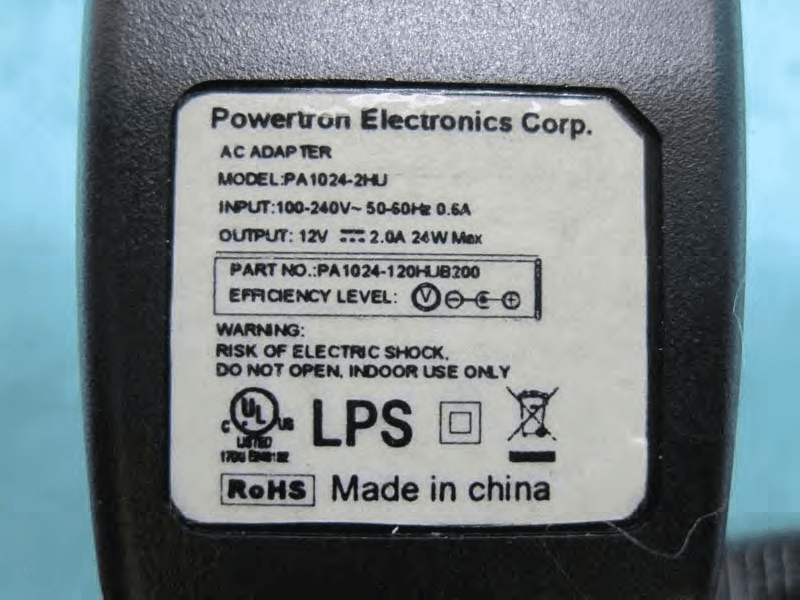
WBV-AP3X0
Aug 28, 2013Access Point
Equipment Class
NII - Unlicensed National Information Infrastructure TX
WBV-HIVEAP1X1
Jun 07, 2012AP Router
Equipment Class
DTS - Digital Transmission System