WCGP5EG3Ethernet Gateway
Packet Power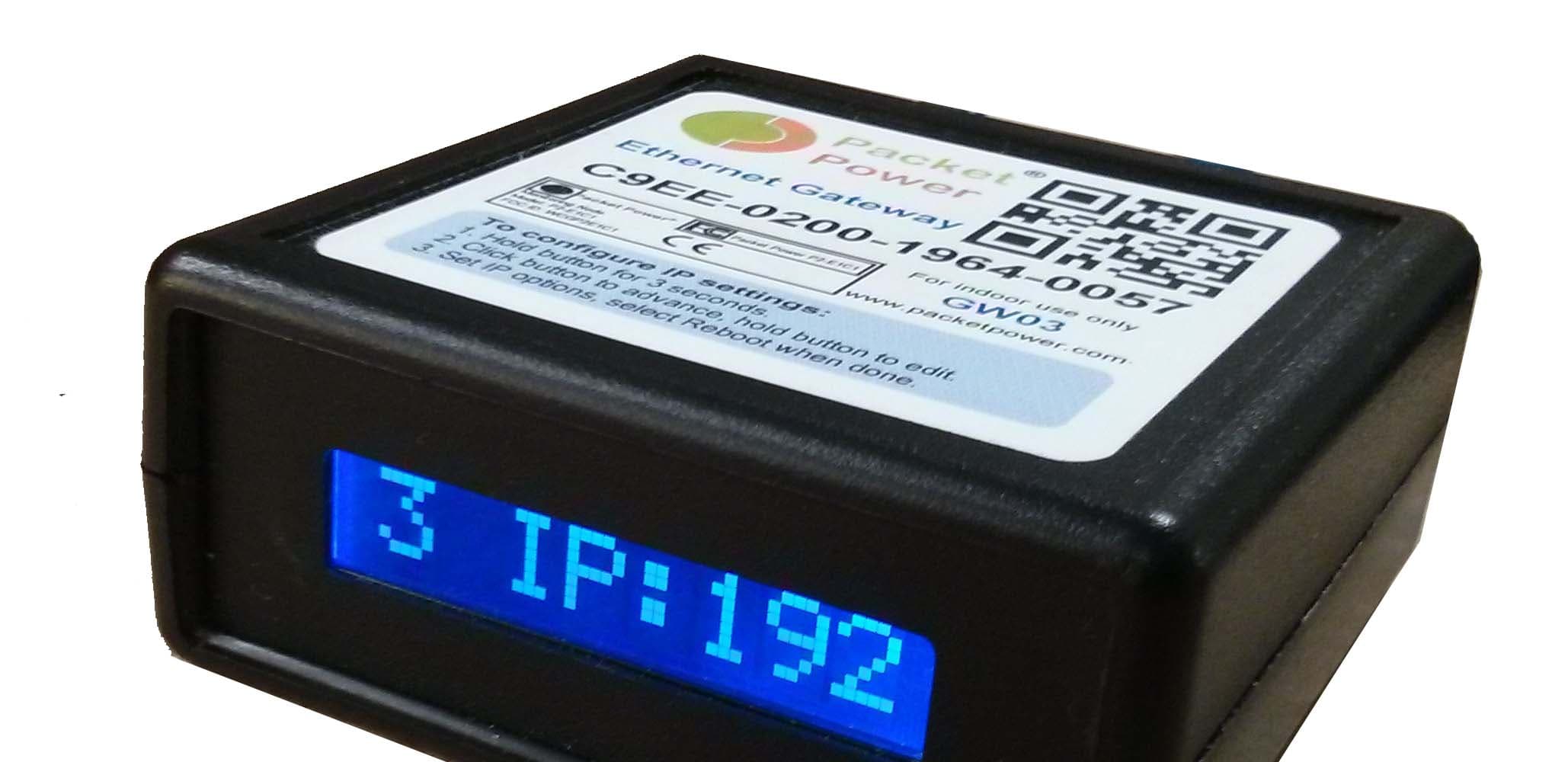
Click to zoom
Application Details
- Equipment Class
- DSS - Part 15 Spread Spectrum Transmitter
- Date of Grant
- Feb 01, 2015
- Application Purpose
- Original Equipment
- Date of Application
- Feb 01, 2015
- Equipment Note
- Ethernet Gateway
- Frequency Range
- 902.40000000 - 927.60000000
- Company
- Packet Power
- Country
- United States
Documents & Files
Document Text
Text extracted from the exhibit documents filed with the FCC. Open a document above to read the original.
Users Manual
Packet Power™ Ethernet Gateway Version 3 Users Manual Version 1.1 Packet Power, LLC 233 Park Avenue, Suite 203 Minneapolis, MN 55415 1-877-560-8770 Email: [email protected] www.packetpower.com NOTES Read all instructions carefully prior to installation. No field-serviceable parts. Do not attempt to disassemble the product as potentially severe electrical shock may result. Installation and maintenance must be performed by qualified personnel. Follow basic safety precautions to reduce the risk of electrical shock and damage to equipment. Store in a clean, dry location. Clean with a dry cloth. Intended for indoor use only, do not install in a wet location. Adhere to all local electrical codes and guidelines. REGULATORY INFORMATION This product has been certified to meet the following requirements: UL / ANSI standards 61010-1,Second Edition, Dated July 12, 2004 with revisions through and including October 28, 2008 CAN/CSA-C22.2 No. 61010-1, second edition, including Amendment 1, or a later version of the same standard incorporating the same level of testing requirements. Council Directive 2006/95/EC (December 12, 2006) on Low Voltage Equipment Safety; IEC 61010-1:2001 (Second Edition) and EN 61010-1:2001 (Second Edition) Council Directive 1999/05/EC - European Union (EU) Radio & Telecommunications Terminal Equipment Directive (R&TTE) ETSI EN 300 220-2, Issued:2006/04/01 and ETSI EN 301 489-3, Issued:2002/08/01 V1.4.1 Council Directive 2004/108/EC (December 15, 2004) on Electromagnetic Compatibility CENELEC EN 61326-1 Issued:2006/05/01; IEC 61326-1:2005;:1997 – AS/NZS 4268: 2008 Class B Device Statement / FCC Regulations: Section 15.105(a) of the FCC Rules: This equipment has been tested and found to comply with the limits for a Class B digital device, pursuant to part 15 of the FCC Rules. These limits are designed to provide reasonable protection against harmful interference when the equipment is operated in a commercial environment. This equipment generates, uses, and can radiate radio frequency energy and, if not installed and used in accordance with the instruction manual, may cause harmful interference to radio communications. Section 15.19 of the FCC Rules: This device complies with part 15 of the FCC Rules. Operation is subject to the following two conditions: (1) This device may not cause harmful interference, and (2) this device must accept any interference received, including interference that may cause undesired operation. Pursuant to Part 15.21 of the FCC Rules, any changes or modifications to this product not expressly approved by Packet Power LLC might cause harmful interference and void the FCC authorization to operate this product. Pursuant to part 2.1091c of the FCC rules device is categorically excluded from routine RF Exposure regulations. Industry Canada (IC) Compliance Statement This device complies with Industry Canada license-exempt RSS standard(s). Operation is subject to the following two conditions: (1) This device may not cause interference, and (2) this device must accept any interference, including interference that may cause undesired operation of the device. Under Industry Canada regulations, this radio transmitter may only operate using an antenna of a type and maximum (or lesser) gain approved for the transmitter by Industry Canada. To reduce potential radio interference to other users, the antenna type and its gain should be so chosen that the equivalent isotropically radiated power (e.i.r.p.) is not more than that necessary for successful communication. Per section RSS-102, 2.5 of Industry Canada regulations, this device is categorically excluded from Routine Evaluation Limits. Industrie Canada (IC) Déclaration de conformité Le présent appareil est conforme aux CNR d'Industrie Canada applicables aux appareils radio exempts de licence. L'exploitation est autorisée aux deux conditions suivantes : (1) l'appareil ne doit pas produire de brouillage, et (2) l'utilisateur de l'appareil doit accepter tout brouillage radioélectrique subi, même si le brouillage est susceptible d'en compromettre le fonctionnement. Conformément à la réglementation d'Industrie Canada, le présent émetteur radio peut fonctionner avec une antenne d'un type et d'un gain maximal (ou inférieur) approuvé pour l'émetteur par Industrie Canada. Dans le but de réduire les risques de brouillage radioélectrique à l'intention des autres utilisateurs, il faut choisir le type d'antenne et son gain de sorte que la puissance ipoosotrope rayonnée équivalente (p.i.r.e.) ne dépasse pas l'intensité nécessaire à l'établissement d'une communication satisfaisante. Packet Power™ Ethernet Gateway Version 3 Product Manual Copyright 2014 © Packet Power, LLC. 1 Overview The Ethernet Gateway version 3 is the central Gateway by which all Packet Power monitoring nodes (environmental and power) communicate. This guide is intended to provide a high level overview of how to commission a Gateway module. Refer to the support section of www.packetpower.com for additional support. Introduction to the Gateway Gateway Placement: Gateway placement is critical. Gateway module(s) should be located 10-30 meters / 30-100 feet from one or more monitoring nodes (ideally line of site). The network is designed as a mesh network which means that the signal for distant nodes can be relayed through adjacent nodes until reaching nodes in good radio proximity to the Gateway. Refer to the Gateway Placement manual on the support section of the website for additional details. Locate the gateway at a height above monitoring nodes when possible in a location with the best line of sight view of monitoring nodes. Do not locate inside metallic cabinets or directly on metal surfaces Use the Gateway mounting bracket for optimal placement and signal strength. Redundant Gateways are advised for any critical environment; additional Gateways should be placed in midway or in the opposite end of the device constellation whe…
Text truncated - open the document above for the full version.
Cover Letter(s)
Packet Power, LLC Phone +1(877)560-8770 Fax +1(866)324-2511 www.packetpower.com 2716 Summer St NE , Minneapolis, MN 55413 USA December 1, 2014 Compliance Testing LLC 1724 S. Nevada Way Mesa, AZ 85204 To whom it may concern: I, the undersigned, hereby authorize Diana Williams at Compliance Testing, LLC, to act on our behalf in all manners relating to application for equipment authorization, including signing of all documents relating to these matters. Any and all acts carried out by Compliance Testing, LLC on our behalf shall have the same effect as acts of our own. I, the undersigned, hereby certify that we are not subject to a denial of federal benefits, that includes FCC benefits, pursuant to Section 5301 of the Anti-Drug Abuse Act of 1988, 21 U.S.C. 853(a). In authorizing Compliance Testing, LLC as our agent, we still recognize that we are responsible to: a) comply with the relevant provisions of the certification program; b) make all necessary arrangements for the conduct of the evaluation, including provision for examining documentation and access to all areas, records (including internal audit reports) and personnel for the purposes of evaluation (e.g. testing, inspection, assessment, surveillance, reassessment) and resolution of complaints; c) make claims regarding certification only in respect of the scope for which certification has been granted; d) do not use our product certification in such a manner as to bring the Certification Division into disrepute and not make any statement regarding our product Packet Power, LLC Phone 1(877)560-8770 Fax 1(866)324-2511 www.packetpower.com 201 6 th St. SE, Suite #1, Minneapolis, MN 55414 USA 2 certification which the Certification Division may consider misleading or unauthorized; e) upon suspension or cancellation of certification, discontinue use of all advertising matter that contains any reference thereto and return any certification documents as required by the Certification Division; f) use certification only to indicate the products are certified as being in conformity with specified standards; g) endeavor to ensure that no certificate or report nor any part thereof is used in a misleading manner; h) ensure that any reference to our product certification in communication media such as documents, brochures or advertising, complies with the requirements of the Certification Division; i) keep a record of all complaints made known to the us relating to the product’s compliance with requirements of the relevant standard and to make these records available to the Certification Division when requested; j) take appropriate action with respect to such complaints and any deficiencies found in products or services that affect compliance with the requirements for certification; k) document the actions taken. This authorization is valid until further written notice from the applicant. Sincerely Yours, Steve VanTassel CEO Packet Power LLC Packet Power, LLC Phone 1(877)560-8770 Fax 1(866)324-2511 www.packetpower.com 201 6 th St. SE, Suite #1, Minneapolis, MN 55414 USA 3 REMARK: 1. This authorization letter will be sent along with your application when filing with the Certification Division. 2. Please follow the format and type it on company letterhead and send original to us. 3. Authorized signature must be in agreement with grantee code contact in FCC database.
Cover Letter(s)
Packet Power, LLC Phone +1(877)560-8770 Fax +1(866)324-2511 www.packetpower.com 2716 Summer St NE , Minneapolis, MN 55413 USA December 1, 2014 Compliance Testing LLC 1724 S. Nevada Way Mesa, AZ 85204 RE: CONFIDENTIALITY REQUEST FOR SMART POWER CABLE/P5EG3, FCC ID: WCGP5EG3 To Whom It May Concern: This letter serves as an official request for confidentiality under sections 0.457 and 0.459 of CFR 47. We have requested that the following documents required to be submitted with this application be permanently withheld from public review. • Block Diagram • Schematics Parts List • Theory of Operation These documents contain detailed system and equipment descriptions and related information about the product, which manufacturer/applicant considers to be proprietary, confidential, and a custom design and otherwise, would not release to the general public. Since this design is a basis from which future technological products will evolve, manufacturer/applicant feels that this information would be of benefit to its competitors, and that the disclosure of the information in these documents would give our competitors an unfair advantage in the market. Please contact me if there is any information you may need. Sincerely Yours, Steve VanTassel CEO Packet Power LLC
Cover Letter(s)
Packet Power, LLC Phone +1(877)560-8770 Fax +1(866)324-2511 www.packetpower.com 2716 Summer St NE , Minneapolis, MN 55413 USA December 1, 2014 Compliance Testing LLC 1724 S. Nevada Way Mesa, AZ 85204 RE: Short Term Confidentiality Request For Smart Power Cable, model P5EG3, FCC ID: WCGP5EG3 To Whom It May Concern: In accordance with sections 0.457 and 0.459 of CFR 47, Packet Power LLC. requests short‐term Confidentiality of following sections of this application for a period of 45 days after grant is issued. 1. Test setup photos 2. External photos 3. Internal photos 4. User’s manual These documents contain detailed system and equipment descriptions and related information about the product, which manufacturer/applicant considers to be proprietary, confidential, and a custom design and otherwise, would not release to the general public. Since this design is a basis from which future technological products will evolve, manufacturer/applicant feels that this information would be of benefit to its competitors, and that the disclosure of the information in these documents would give our competitors an unfair advantage in the market. Grantee will not market or distribute product during the period requested. Once product is available for marketing, Grantee will notify FCC or TCB. Please contact me if there is any information you may need. Sincerely, Steve VanTassel CEO Packet Power LLC 2716 Summer St. NE, Minneapolis, MN, 55413 (877) 560-8770 [email protected]
Cover Letter(s)
P5EG3 Antenna Specification Wire ● Insulated AWG20 (0.81mm diameter) solid copper wire ● Black for antenna 1 ● Red for antenna 2 Antenna 1 (BLACK) (ANT1) ● Insulated AWG20 BLACK solid wire ● 82mm (+/‐2mm) total length, 3mm stripped for soldering Antenna 2 (RED) (ANT2) ● Insulated AWG20 RED solid wire ● 35mm (+/‐2mm) total length, 3mm stripped for soldering
Cover Letter(s)
P5 Device Family R/F Channel Dwell Time Overview All Packet Power P5family devices (P5T3, P5T1, P5J6 etc.) use identical hardare and software R/F communication systems. The system uses a pseudorandom frequency hopping scheme, with packets transmission times of 7ms (in 2.4GHz band) or 10ms (in 860/920MHz bands). Minimum time between any two transmissions (always on different channels) is: 2^9 * 22.5ms = 11.52s, Maximum time between between such transmissions is: 2^12 * 22.5ms = 92.16s. Minimum time between consecutive transmissions on the same channel (out of 64) is: 64 * 2^9 * 22.5ms = 737s. Packet Power L.L.C. Strictly Proprietary & Confidential
Test Report
p14b0017_FCC_Part 15.247_FHSS_Rev 3.0 Page 1 of 21 Test Report Prepared for: Packet Power, LLC Model: P5EG3 Description: Ethernet Gateway Serial Number: N/A FCC ID: WCGP5EG3 IC: 8751A-P5EG3 To FCC Part 15.247 FHSS Date of Issue: January 30, 2015 On the behalf of the applicant: Packet Power, LLC 2716 Summer St NE Minneapolis, MN 55413 Attention of: Steve VanTassel, CEO Ph: (612) 396-8704 E-mail: [email protected] Prepared by Compliance Testing, LLC 1724 S. Nevada Way Mesa, AZ 85204 (480) 926-3100 phone / (480) 926-3598 fax www.compliancetesting.com Project No: p14b0017 Alex Macon Project Test Engineer This report may not be reproduced, except in full, without written permission from Compliance Testing. All results contained herein relate only to the samples tested. p14b0017_FCC_Part 15.247_FHSS_Rev 3.0 Page 2 of 21 Test Report Revision History Revision Date Revised By Reason for Revision 1.0 December 15, 2014 Alex Macon Original Document 2.0 January 13, 2015 Amanda Reed Added asset i00273 to equipment table 3.0 January 30, 2015 Alex Macon Added BW Plots and Timing explanation p14b0017_FCC_Part 15.247_FHSS_Rev 3.0 Page 3 of 21 Table of Contents Description Page Standard Test Conditions and Engineering Practices 6 Test Results Summary 7 Peak Output Power 9 Radiated Spurious Emissions 10 Emissions at Band Edges 11 Occupied Bandwidth 16 Dwell Time 18 Number of Hopping Channels 19 Test Equipment Utilized 21 p14b0017_FCC_Part 15.247_FHSS_Rev 3.0 Page 4 of 21 ILAC / A2LA Compliance Testing, LLC, has been accredited in accordance with the recognized International Standard ISO/IEC 17025:2005. This accreditation demonstrates technical competence for a defined scope and the operation of a laboratory quality management system (refer to the joint ISO-ILAC-IAF Communiqué dated January 2009). The tests results contained within this test report all fall within our scope of accreditation, unless noted in the table below. Please refer to http://www.compliancetesting.com/labscope.html for current scope of accreditation. Testing Certificate Number: 2152.01 FCC Site Reg. #349717 IC Site Reg. #2044A-2 Non-accredited tests contained in this report: N/A p14b0017_FCC_Part 15.247_FHSS_Rev 3.0 Page 5 of 21 The applicant has been cautioned as to the following 15.21 - Information to User The user’s manual or instruction manual for an intentional radiator shall caution the user that changes or modifications not expressly approved by the party responsible for compliance could void the user’s authority to operate the equipment. 15.27(a) - Special Accessories Equipment marketed to a consumer must be capable of complying with the necessary regulations in the configuration in which the equipment is marketed. Where special accessories, such as shielded cables and/or special connectors are required to enable an unintentional or intentional radiator to comply with the emission limits in this part, the equipment must be marketed with, i.e. shipped and sold with, those special accessories. However, in lieu of shipping or packaging the special accessories with the unintentional or intentional radiator, the responsible party may employ other methods of ensuring that the special accessories are provided to the consumer, without an additional charge. Information detailing any alternative method used to supply the special accessories for a grant of equipment authorization or retained in the verification records, as appropriate. The party responsible for the equipment, as detailed in 2.909 of this chapter, shall ensure that these special accessories are provided with the equipment. The instruction manual for such devices shall include appropriate instructions on the first page of text concerned with the installation of the device that these special accessories must be used with the device. It is the responsibility of the user to use the needed special accessories supplied with the equipment. p14b0017_FCC_Part 15.247_FHSS_Rev 3.0 Page 6 of 21 Standard Test Conditions and Engineering Practices All tests and measurement data shown were performed in accordance with FCC Rules and Regulations, Volume II; Part 2 and the following individual Parts: 15.247 Operation within bands 902-928 MHz, 2400-2483.5 MHz, and 5725-5850 MHz. Except as noted herein, the following conditions and procedures were observed during the testing: In accordance with ANSI C63.4-2009, ANSI C63.10-2009, FCC DA 00-705, and unless otherwise indicated in the specific measurement results, the ambient temperature of the actual EUT was maintained within the range of 10 to 40C (50 to 104F) unless the particular equipment requirements specified testing over a different temperature range. Also, unless otherwise indicated, the humidity levels were in the range of 10% to 90% relative humidity. Environmental Conditions Temperature (°C) Humidity % Pressure mbar 24.3 – 21.7 36.4 – 41.9 967.1 – 971.2 Measurement results, unless otherwise noted, are worst case measurements. p14b0017_FCC_Part 15.247_FHSS_Rev 3.0 Page 7 of 21 Test Results Summary Specification Test Name Pass, Fail, N/A Comments 15.247(b) Peak Output Power Pass 15.247(d) Conducted Spurious Emissions N/A Device incorporates an integral antenna. 15.247(d), 15.209(a), 15.205 Radiated Spurious Emissions Pass 15.247(d), 15.209(a), 15.205 Emissions At Band Edges Pass 15.247(a) Occupied Bandwidth Pass 15.247(a) Dwell Time Pass 15.247(a) Number of Hopping Channels Pass 15.207 A/C Powerline Conducted Emissions N/A EUT is a DC powered device p14b0017_FCC_Part 15.247_FHSS_Rev 3.0 Page 8 of 21 EUT Description Model: P5EG3 Description: Ethernet Gateway Software: NMX Packet Power URL Serial Number: N/A Additional Information: The EUT is an Ethernet Gateway which incorporates a 2.4 GHz radio with an integral antenna. EUT Operation during Tests EUT was placed in test modes using the NMX Packet Power URL paired with the node configurator. 15.203: Antenna Requirement: X The antenna is permanently attached to the EUT The antenna uses a …
Text truncated - open the document above for the full version.
Test Report
p14b0017_FCC_Part 15.247_FHSS_Rev 2.0 Page 1 of 17 Test Report Prepared for: Packet Power, LLC Model: P5EG3 Description: Ethernet Gateway Serial Number: N/A FCC ID: WCGP5EG3 IC: 8751A-P5EG3 To FCC Part 15.247 FHSS Date of Issue: January 30, 2015 On the behalf of the applicant: Packet Power, LLC 2716 Summer St NE Minneapolis, MN 55413 Attention of: Steve VanTassel, CEO Ph: (612) 396-8704 E-mail: [email protected] Prepared by Compliance Testing, LLC 1724 S. Nevada Way Mesa, AZ 85204 (480) 926-3100 phone / (480) 926-3598 fax www.compliancetesting.com Project No: p14b0017 Alex Macon Project Test Engineer This report may not be reproduced, except in full, without written permission from Compliance Testing. All results contained herein relate only to the sample tested. p14b0017_FCC_Part 15.247_FHSS_Rev 2.0 Page 2 of 17 Test Report Revision History Revision Date Revised By Reason for Revision 1.0 December 15, 2014 Alex Macon Original Document 2.0 January 30, 2015 Alex Macon Updated Timing explanation, added Restricted Band plot and added antenna gain information p14b0017_FCC_Part 15.247_FHSS_Rev 2.0 Page 3 of 17 Table of Contents Description Page Standard Test Conditions and Engineering Practices 6 Test Results Summary 7 Peak Output Power 9 Radiated Spurious Emissions 10 Emissions at Band Edges 11 Occupied Bandwidth 14 Dwell Time 15 Number of Hopping Channels 16 Test Equipment Utilized 17 p14b0017_FCC_Part 15.247_FHSS_Rev 2.0 Page 4 of 17 ILAC / A2LA Compliance Testing, LLC, has been accredited in accordance with the recognized International Standard ISO/IEC 17025:2005. This accreditation demonstrates technical competence for a defined scope and the operation of a laboratory quality management system (refer to the joint ISO-ILAC-IAF Communiqué dated January 2009). The tests results contained within this test report all fall within our scope of accreditation, unless noted in the table below. Please refer to http://www.compliancetesting.com/labscope.html for current scope of accreditation. Testing Certificate Number: 2152.01 FCC Site Reg. #349717 IC Site Reg. #2044A-2 Non-accredited tests contained in this report: N/A p14b0017_FCC_Part 15.247_FHSS_Rev 2.0 Page 5 of 17 The applicant has been cautioned as to the following 15.21 - Information to User The user’s manual or instruction manual for an intentional radiator shall caution the user that changes or modifications not expressly approved by the party responsible for compliance could void the user’s authority to operate the equipment. 15.27(a) - Special Accessories Equipment marketed to a consumer must be capable of complying with the necessary regulations in the configuration in which the equipment is marketed. Where special accessories, such as shielded cables and/or special connectors are required to enable an unintentional or intentional radiator to comply with the emission limits in this part, the equipment must be marketed with, i.e. shipped and sold with, those special accessories. However, in lieu of shipping or packaging the special accessories with the unintentional or intentional radiator, the responsible party may employ other methods of ensuring that the special accessories are provided to the consumer, without an additional charge. Information detailing any alternative method used to supply the special accessories for a grant of equipment authorization or retained in the verification records, as appropriate. The party responsible for the equipment, as detailed in 2.909 of this chapter, shall ensure that these special accessories are provided with the equipment. The instruction manual for such devices shall include appropriate instructions on the first page of text concerned with the installation of the device that these special accessories must be used with the device. It is the responsibility of the user to use the needed special accessories supplied with the equipment. p14b0017_FCC_Part 15.247_FHSS_Rev 2.0 Page 6 of 17 Standard Test Conditions and Engineering Practices All tests and measurement data shown were performed in accordance with FCC Rules and Regulations, Volume II; Part 2 and the following individual Parts: 15.247 Operation within bands 902-928 MHz, 2400-2483.5 MHz, and 5725-5850 MHz. Except as noted herein, the following conditions and procedures were observed during the testing: In accordance with ANSI C63.4-2009, ANSI C63.10-2009, FCC DA 00-705, and unless otherwise indicated in the specific measurement results, the ambient temperature of the actual EUT was maintained within the range of 10 to 40C (50 to 104F) unless the particular equipment requirements specified testing over a different temperature range. Also, unless otherwise indicated, the humidity levels were in the range of 10% to 90% relative humidity. Environmental Conditions Temperature (°C) Humidity (%) Pressure (mbar) 24.3 – 21.7 36.4 – 41.9 967.1 – 971.2 Measurement results, unless otherwise noted, are worst case measurements. p14b0017_FCC_Part 15.247_FHSS_Rev 2.0 Page 7 of 17 Test Results Summary Specification Test Name Pass, Fail, N/A Comments 15.247(b) Peak Output Power Pass 15.247(d) Conducted Spurious Emissions N/A Device incorporates an integral antenna. 15.247(d), 15.209(a), 15.205 Radiated Spurious Emissions Pass 15.247(d), 15.209(a), 15.205 Emissions At Band Edges Pass 15.247(a) Occupied Bandwidth Pass 15.247(a) Dwell Time Pass 15.247(a) Number of Hopping Channels Pass 15.207 A/C Powerline Conducted Emissions N/A EUT is a DC powered device p14b0017_FCC_Part 15.247_FHSS_Rev 2.0 Page 8 of 17 EUT Description Model: P5EG3 Description: Ethernet Gateway Firmware: N/A Software: NMX Packet Power URL Serial Number: N/A Additional Information: The EUT is an Ethernet Gateway which incorporates a 900 MHz radio with an integral antenna. EUT Operation during Tests EUT was placed in test modes using the NMX Packet Power URL paired with the node configurator. 15.203: Antenna Requirement: X The antenna is permanently attached to the EUT The antenna uses a un…
Text truncated - open the document above for the full version.
Test Setup Photos
Test Setup Photos FCC ID: WCGP5EG3 IC: 8751A-P5EG3 RF Radiated #1 RF Radiated #2
Contact Information
Applicant
Paul Bieganski
Test Firm
Compliance Testing, LLCMichael Schafer
Technical Specifications
| # | Rule Parts | Frequency Range | Power Output |
|---|---|---|---|
| 2 | 15C | 902.4 MHz - 927.6 MHz | 200.00 µW |
Other Applications from Packet Power
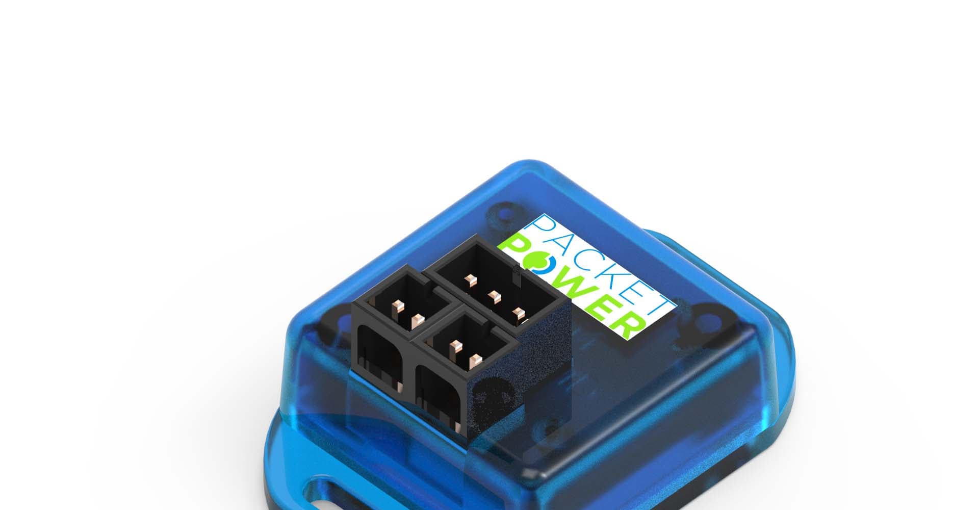
WCGP5C
Jul 31, 2015Wireless Power Monitor
Equipment Class
DXX - Part 15 Low Power Communication Device Transmitter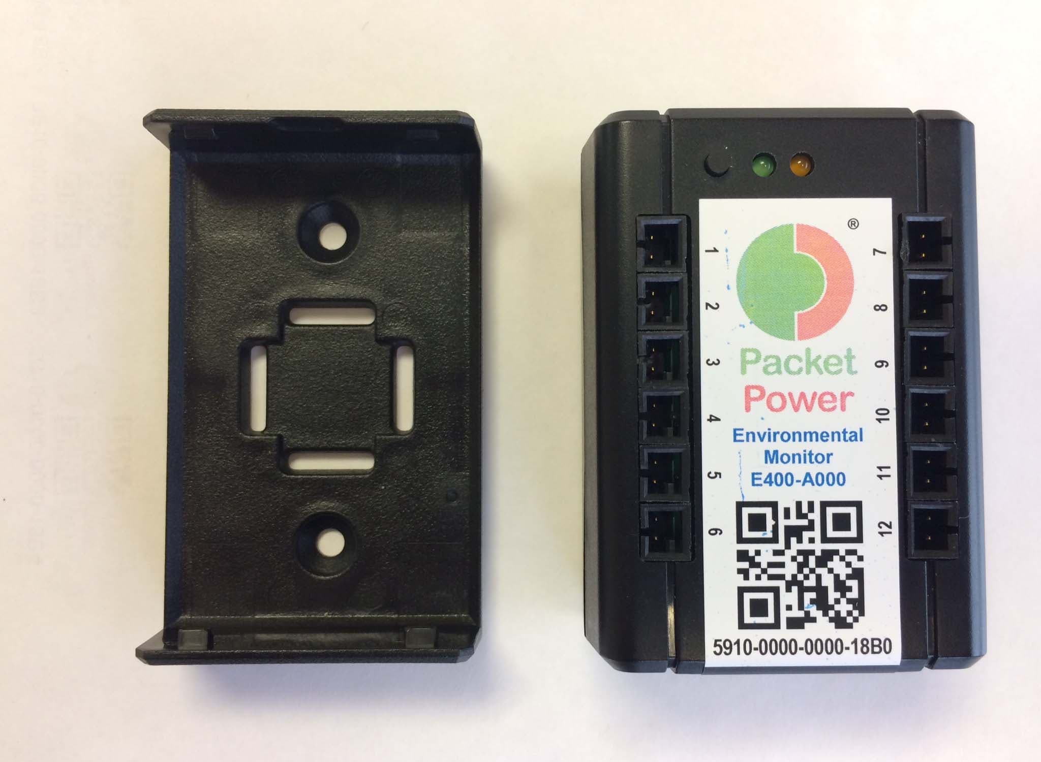
WCGP5EMB1
Feb 05, 2015Ethernet Gateway
Equipment Class
DSS - Part 15 Spread Spectrum Transmitter
WCGP5J6
Feb 05, 2015Ethernet Gateway
Equipment Class
DSS - Part 15 Spread Spectrum Transmitter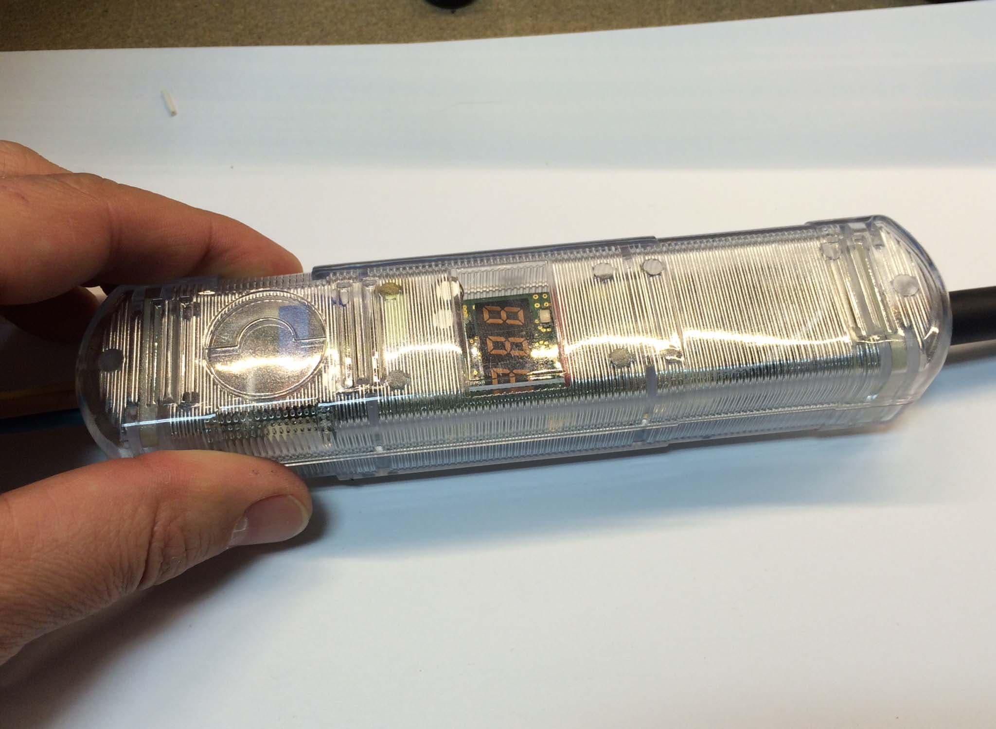
WCGP5T1
Feb 02, 2015Ethernet Gateway
Equipment Class
DSS - Part 15 Spread Spectrum Transmitter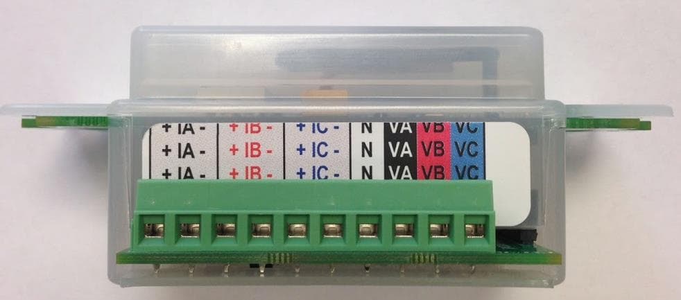
WCGP5T3
Apr 09, 2014Power Monitoring Node
Equipment Class
DSS - Part 15 Spread Spectrum Transmitter