WCGP5T3Power Monitoring Node
Packet Power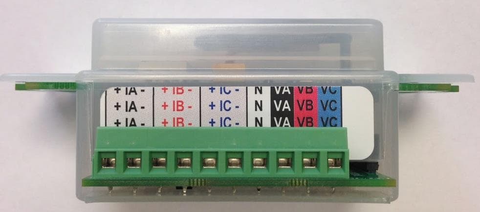
Click to zoom
Application Details
- Equipment Class
- DSS - Part 15 Spread Spectrum Transmitter
- Date of Grant
- Apr 09, 2014
- Application Purpose
- Original Equipment
- Date of Application
- Apr 09, 2014
- Equipment Note
- Power Monitoring Node
- Frequency Range
- 902.40000000 - 927.60000000
- Company
- Packet Power
- Country
- United States
Documents & Files
Document Text
Text extracted from the exhibit documents filed with the FCC. Open a document above to read the original.
Users Manual
Packet Power™ Power Monitoring Module DRAFT Instructions for Use Version 0.3 Packet Power, LLC 2716 Summer St NE Minneapolis, MN 55413 1-877-560-8770 Email: [email protected] www.packetpower.com Indicates a POTENTIAL HAZARD. Consult documentation carefully. CAUTION Read all instructions carefully prior to installation. The Power Monitoring Module should only be connected to the type of power source indicated on the label. Adhere to voltage and amperage guidelines and utilize a proper branch circuit protector. No field-serviceable parts. Do not attempt to disassemble the product as potentially severe electrical shock may result. Installation and maintenance must be performed by qualified personnel. Follow basic safety precautions to reduce the risk of electrical shock and damage to equipment. Store in a clean, dry location. Clean with a dry cloth. Intended for indoor use only, do not install in a wet location. Adhere to all local electrical codes and guidelines. Failure to use the product in the specified manner may lead to injury or death and damage to equipment. Regulatory Information [this will need to be updated following certification] This product has been tested to the following requirements: UL / ANSI standards 61010-1,Second Edition, Dated July 12, 2004 with revisions through and including October 28, 2008 CAN/CSA-C22.2 No. 61010-1, second edition, including Amendment 1, or a later version of the same standard incorporating the same level of testing requirements. Council Directive 2006/95/EC (December 12, 2006) on Low Voltage Equipment Safety; IEC 61010-1:2001 (Second Edition) and EN 61010-1:2001 (Second Edition) IEC 61010-2-032 (2002) 2nd Edition Handheld Electrical Test and Measure [Need to verify correct EN standards to cite] Council Directive 1999/05/EC - European Union (EU) Radio & Telecommunications Terminal Equipment Directive (R&TTE) ETSI EN 300 220-2, Issued:2006/04/01 and ETSI EN 301 489-3, Issued:2002/08/01 V1.4.1 Council Directive 2004/108/EC (December 15, 2004) on Electromagnetic Compatibility CENELEC EN 61326-1 Issued:2006/05/01; IEC 61326-1:2005;:1997 - Class B Device Statement: Section 15.105(a) of the FCC Rules: This equipment has been tested and found to comply with the limits for a Class B digital device, pursuant to part 15 of the FCC Rules. These limits are designed to provide reasonable protection against harmful interference when the equipment is operated in a commercial environment. This equipment generates, uses, and can radiate radio frequency energy and, if not installed and used in accordance with the instruction manual, may cause harmful interference to radio communications. Section 15.19 of the FCC Rules: This device complies with part 15 of the FCC Rules. Operation is subject to the following two conditions: (1) This device may not cause harmful interference, and (2) this device must accept any interference received, including interference that may cause undesired operation. Pursuant to Part 15.21 of the FCC Rules, any changes or modifications to this product not expressly approved by Packet Power LLC might cause harmful interference and void the FCC authorization to operate this product. Industry Canada (IC) Compliance Statement This device complies with Industry Canada license-exempt RSS standard(s). Operation is subject to the following two conditions: (1) This device may not cause interference, and (2) this device must accept any interference, including interference that may cause undesired operation of the device. Under Industry Canada regulations, this radio transmitter may only operate using an antenna of a type and maximum (or lesser) gain approved for the transmitter by Industry Canada. To reduce potential radio interference to other users, the antenna type and its gain should be so chosen that the equivalent isotropically radiated power (e.i.r.p.) is not more than that necessary for successful communication. Industrie Canada (IC) Déclaration de conformité Le présent appareil est conforme aux CNR d'Industrie Canada applicables aux appareils radio exempts de licence. L'exploitation est autorisée aux deux conditions suivantes : (1) l'appareil ne doit pas produire de brouillage, et (2) l'utilisateur de l'appareil doit accepter tout brouillage radioélectrique subi, même si le brouillage est susceptible d'en compromettre le fonctionnement. Conformément à la réglementation d'Industrie Canada, le présent émetteur radio peut fonctionner avec une antenne d'un type et d'un gain maximal (ou inférieur) approuvé pour l'émetteur par Industrie Canada. Dans le but de réduire les risques de brouillage radioélectrique à l'intention des autres utilisateurs, il faut choisir le type d'antenne et son gain de sorte que la puissance isotrope rayonnée équivalente (p.i.r.e.) ne dépasse pas l'intensité nécessaire à l'établissement d'une communication satisfaisante. Packet Power™ Monitoring Module Users Manual Copyright 2009-2013 Packet Power, LLC. i Safety summary and specifications This general safety information is to be used by both the Power Monitoring Module (PMM) operator and servicing personnel. Packet Power LLC assumes no liability for user’s failure to comply with these safety guidelines. Please read this manual carefully before proceeding. This symbol is used throughout this manual to indicate critical safety information. Failure to observe the information following this symbol may result in injury or death. CAUTION: This PMM and the area it is installed in may contain life threatening voltages. Qualified personnel must disconnect all high voltage wiring before using or servicing the PMM. PMM should only be connected to the type of power source indicated on the label. Do not overload the PMM as this can result in a risk of fire or electrical shock. PMM should be deployed in conjunction with proper branch circuit protectors. The current transformer(s) used with the PMM must be appropriate to the amperage of the circui…
Text truncated - open the document above for the full version.
Cover Letter(s)
Packet Power, LLC Phone & Fax: +1(877)560-8770 www.packetpower.com March 26, 2013 Federal Communications Commission 7435 Oakland Mills Road Columbia MD 21046 Subject: Limited Modular Approval FCC ID: FCC ID WCG [WCGP5T3P] Dear Sir/Madam: Enclosed please find the Modular Approval checklist. We are seeking limited modular approval on that basis that the product meets all requirements when used in the prescribed manner as indicated in the End Product Control section. Should you have any questions, please feel free to contact the undersigned. Sincerely, Steve VanTassel Tele: 1-612-396-8704 Fax: 1-866-321-2511 Email: [email protected] Packet Power, LLC Phone & Fax: +1(877)560-8770 www.packetpower.com Modular Approval Checklist Modular approval requirement Yes No (a) The radio elements must have the radio frequency circuitry must be shielded. Physical/discrete and tuning capacitors may be located external to the shield, but must be on the module assembly. No See Note 1 (b) The module shall have buffered modulation/data input(s) (if such inputs are provided) to ensure that the module will comply with the requirements set out in the applicable RSS standard under conditions of excessive data rates or over- modulation. Yes (c) The module shall have its own power supply regulation on the module. This is to ensure that the module will comply with the requirements set out in the applicable standard regardless of the design of the power supplying circuitry in the host device which houses the module. Yes (d) The module shall comply with the provisions for external power amplifiers and antennas detailed in this standard. The equipment certification submission shall contain a detailed description of the configuration of all antennas that will be used with the module. Yes (e) The module shall be tested for compliance with the applicable standard in a stand-alone configuration, i.e. the module must not be inside another device during testing. Yes (f) The module shall comply with the Category I equipment labeling requirements. Yes g) The module shall comply with applicable RSS-102 exposure requirements, which are based on the intended use/configurations. Yes (h) Is the modular device for an Industry Canada licensed exempt service? Yes Note 1 : The PMM, including all radio components, is permanently enclosed in a highly impact resistant Lexan enclosure. Modules are sold for installation into a specific class of devices known as Power Distribution Units ("PDUs"), which are industrial-grade metal multi-outlet “power strips”. All PDU-type devices have to be completely grounded for safety reasons. The module is always installed in devices with grounded metal enclosures, with a metal front plate with only the antenna (permanently enclosed in Lexan) protruding through the plane of the front plate. All radio components of the PMM are contained within Packet Power, LLC Phone & Fax: +1(877)560-8770 www.packetpower.com the metal enclosure. The module is permanently installed under strict guidelines by highly qualified OEMs who can acquire modules only directly from Packet Power. Additional installations of the product always utilize similar installation requirements with the device housed in a grounded chassis, with only the antenna (enclosed in Lexan) protruding from the device. Radio components of the device are contained within the metal enclosure. Any installation takes place under strict guidelines by highly qualified OEMs who can acquire modules only directly from Packet Power. For additional details please see the separate document : Packet Power PMM – RF Shielding.pdf, End Product Control (Section 3.2.3 of RSS-Gen) The Packet Power PMM module is used within Power Distribution Units (PDUs) such as those manufactured by Geist Manufacturing and others. All PDU devices are housed within grounded sheet metal enclosures for mechanical integrity and safety reasons. The Packet Power PMM module is installed within the metal enclosure of the PDU, with only the antenna (permanently enclosed in Lexan) protruding through the plane of enclosure. All radio components of the PMM are contained within the enclosure. The module is permanently installed under strict guidelines by highly qualified OEMs who can acquire modules only directly from Packet Power. In order for the PMM module to be used within a PDU, the PDU manufacturer must collaborate closely with Packet Power, including determining the exact way in which the module will be mounted within the PDU and the optimum way for the PMM to be incorporated into the PDU’s wiring. Each PMM has a unique serial number, which when used with the configuration utility provides full traceability of each module. Further, the end product manufacturers’ PDU products must meet UL/ANSI and IC safety certification criteria, including the appropriate installation of our monitoring module within a properly grounded enclosure. This provides an additional compliance requirement that is administered by an independent party on an ongoing basis. The PMM module will only be deployed in products that are themselves subject to strict safety certification and are built using manufacturing processes subject to ongoing monitoring.
Cover Letter(s)
Packet Power, LLC Phone +1(877)560-8770 Fax +1(866)324-2511 www.packetpower.com 2716 Summer St NE, Minneapolis, MN 55413 USA Federal Communications Commission 7435 Oakland Mills Road Columbia MD 21046 Subject:Request for Confidentiality FCC ID: FCC ID WCG [WCGP5T3P] To Whom It May Concern: Pursuant to the provisions of Sections 0.457 and 0.459 of the Commission’s rules (47 CFR §§ 0.457, 0.459), we are requesting the Commission to withhold the following attachments as confidential document from public disclosure indefinitely. Schematic Diagram Block Diagram Theory of Operation Parts List Tune-Up Procedure Above mentioned document contains detailed system and equipment description are considered as proprietary information in operation of the equipment. The public disclosure of above documents might be harmful to our company and would give competitor an unfair advantage in the market. Packet Power, LLC Phone 1(877)560-8770 Fax 1(866)324-2511 www.packetpower.com 201 6 th St. SE, Suite #1, Minneapolis, MN 55414 USA 2 In additional to above mentioned documents, pursuant to Public Notice DA 04-1705 of the Commission’s policy, in order to comply with the marketing regulations in 47 CFR §2.803 and the importation rules in 47 CFR §2.1204, while ensuring that business sensitive information remains confidential until the actual marketing of newly authorized devices. We are requesting the commission to grant short-term confidentiality request on the following attachments: External Photos Internal Photos Test Setup Photos User Manual It is our understanding that all measurement test reports, FCC ID label format and correspondent during certification review process cannot be granted as confidential documents and those information will be available for public review once the grant of equipment authorization is issued. Best Regards Steve VanTassel CEO Packet Power LLC March 6, 2014
Cover Letter(s)
Packet Power, LLC Phone +1(877)560-8770 Fax +1(866)324-2511 www.packetpower.com 2716 Summer St NE, Minneapolis, MN 55413 USA March 6, 2013 UL CCS Certification Division 47173 Benicia Street Fremont, CA 94538, USA To whom it may concern: I, the undersigned, hereby authorize UL CCS, to act on our behalf in all manners relating to application for equipment authorization, including signing of all documents relating to these matters. Any and all acts carried out by UL CCS on our behalf shall have the same effect as acts of our own. I, the undersigned, hereby certify that we are not subject to a denial of federal benefits, that includes FCC benefits, pursuant to Section 5301 of the Anti-Drug Abuse Act of 1988, 21 U.S.C. 853(a). In authorizing UL CCS as our agent, we still recognize that we are responsible to: a) comply with the relevant provisions of the certification program; b) make all necessary arrangements for the conduct of the evaluation, including provision for examining documentation and access to all areas, records (including internal audit reports) and personnel for the purposes of evaluation (e.g. testing, inspection, assessment, surveillance, reassessment) and resolution of complaints; c) make claims regarding certification only in respect of the scope for which certification has been granted; Packet Power, LLC Phone 1(877)560-8770 Fax 1(866)324-2511 www.packetpower.com 201 6 th St. SE, Suite #1, Minneapolis, MN 55414 USA 2 d) do not use our product certification in such a manner as to bring the Certification Division into disrepute and not make any statement regarding our product certification which the Certification Division may consider misleading or unauthorized; e) upon suspension or cancellation of certification, discontinue use of all advertising matter that contains any reference thereto and return any certification documents as required by the Certification Division; f) use certification only to indicate the products are certified as being in conformity with specified standards; g) endeavor to ensure that no certificate or report nor any part thereof is used in a misleading manner; h) ensure that any reference to our product certification in communication media such as documents, brochures or advertising, complies with the requirements of the Certification Division; i) keep a record of all complaints made known to the us relating to the product’s compliance with requirements of the relevant standard and to make these records available to the Certification Division when requested; j) take appropriate action with respect to such complaints and any deficiencies found in products or services that affect compliance with the requirements for certification; k) document the actions taken. This authorization is valid until further written notice from the applicant. Sincerely Yours, Steve VanTassel CEO Packet Power LLC Packet Power, LLC Phone 1(877)560-8770 Fax 1(866)324-2511 www.packetpower.com 201 6 th St. SE, Suite #1, Minneapolis, MN 55414 USA 3 REMARK: 1. This authorization letter will be sent along with your application when filing with the Certification Division. 2. Please follow the format and type it on company letterhead and send original to us. 3. Authorized signature must be in agreement with grantee code contact in FCC database.
Cover Letter(s)
1 Chris Harvey From: Ferrer, Michael <[email protected]> Sent: Thursday, March 27, 2014 3:35 PM To: Harvey, Christopher Cc: Harvey, Christopher; Hoque, Claire; [email protected] Subject: RE: Packet Power, //WCGP5T3 //AN14T0142 8751A-P5T3 // AN14I5577 Notice #1 Attachments: Theory of operation 2.pdf Chris This should be the last of your comments. #4 is attached. #5 is below. 5. The Operational Description indicates that the 2.4GHz is using transceiver Nordic Semiconductor nRF51822, but the chip is also referenced as nRF51 in several places, which causes confusion. Please confirm that this reference is to the same chip. A: nRF51822 and nRF51 all refer to the same transceiver Nordic Semiconductor nRF51822. Michael Ferrer, P.E. Project Lead Consumer Technology Division UL Verification Services-EMC --------------------------------------------- UL LLC. 333 Pfingsten Rd. Northbrook, IL 60062 T: (847)-664-1312 W: ul.com -----Original Message----- From: Ferrer, Michael Sent: Thursday, March 20, 2014 3:11 PM To: Harvey, Christopher Cc: Harvey, Christopher; Hoque, Claire; '[email protected]' Subject: RE: Packet Power, //WCGP5T3 //AN14T0142 8751A-P5T3 // AN14I5577 Notice #1 Chris Additional responses. I am still waiting on #4 and 5, but can you review the others and let me know if you have further comments. Thanks Michael Ferrer, P.E. Project Lead Consumer Technology Division UL Verification Services-EMC --------------------------------------------- UL LLC. 333 Pfingsten Rd. Northbrook, IL 60062 T: (847)-664-1312 W: ul.com 2 -----Original Message----- From: Ferrer, Michael Sent: Friday, March 14, 2014 3:04 PM To: Harvey, Christopher Cc: Harvey, Christopher; Hoque, Claire; [email protected] Subject: RE: Packet Power, //WCGP5T3 //AN14T0142 8751A-P5T3 // AN14I5577 Notice #1 Chris Here are my responses for the test report. Still awaiting client responses on the other exhibits. Michael Ferrer, P.E. Project Lead Consumer Technology Division UL Verification Services --------------------------------------------- UL LLC. 333 Pfingsten Rd. Northbrook, IL 60062 T: (847)-664-1312 W: ul.com -----Original Message----- From: [email protected] [mailto:[email protected]] Sent: Thursday, March 13, 2014 8:10 AM To: Ferrer, Michael Cc: Harvey, Christopher; Hoque, Claire; [email protected] Subject: Packet Power, //WCGP5T3 //AN14T0142 8751A-P5T3 // AN14I5577 Notice #1 Dear Michael, You are listed as the Technical Contact for the above referenced TCB application. The following item(s) need(s) to be resolved before the review can be continued: 1. I see that the Block Diagram indicates ¼ wavelength antennas for the 900 MHz and 2.4GHz antennas, but I cannot find these antennas in the Schematic diagram or the Internal/external photos. The Internal Photos seem to show solder points on the PC Board labeled as ANT1 and ANT2, but nothing is connected. The Test Setups seem to show extra wires coming from the EUT. Please confirm that the antennas are provided and connected to the device when marketed. Please provide an updated photo exhibit showing the antennas. If the User Installs/Connects the antennas, please provide an indication how this complies with the FCC antenna requirements of 15.203. A: attached antenna exhibit 2. The FCC Confidentiality Letter references the incorrect FCC ID (and IC) Number(s). Please provide separate FCC and IC Confidentiality letters with the correct identification numbers as the confidentiality requirements for FCC and IC are different and should reference the correct agency requirements (i.e. IC does not have Short Term Confidentiality). A: attached confidentiality letters 3. Please update the Manual to include the wording required by FCC 15.21. 3 A: attached updated manual 4. You have indicated that the hopping sequence is pseudo-random. However, there are several other FCC FHSS requirements that are not yet declared as being compliant in the application referenced above. Please either provide individual declarations of compliance with the following items needed for FCC 15.247 compliance: The hopping sequence is pseudorandom, based on the technical description, but please provide description/example of the sequence. Is each channel used equally on average, based on the technical description? Does the associated system receiver have a compliant input bandwidth, based on the measured 20 dB emission bandwidth? Does the associated system receiver have the ability to hop in synchronization with the transmitter, basedon the technical description? Does the design of the frequency hopping system allow it to comply with all pertinent requirements when presented with a lengthy data stream? Does the frequency hopping system comply with the non-coordination requirement? 5. The Operational Description indicates that the 2.4GHz is using transceiver Nordic Semiconductor nRF51822, but the chip is also referenced as nRF51 in several places, which causes confusion. Please confirm that this reference is to the same chip. 6. The Operational Description indicates an operating frequency of 860-928 MHz and 2400-2483 MHz, but this device has been tested for operation in narrower ranges. Please update this exhibit to indicate the actual frequencies of operation and how this US/Canada model frequency ranges are set and if they can be changed by the user/installer. A: See attached exhibit system overview. From client: The attached revised document states the clarification: (page 3 paragraph 2) The device operates in and was tested ino 902-928MHz and 2402-2480MHz in the US and Canada. The frequency range used by the device is set by the manufacturer prior to shipment to the user and cannot be changed by the user / installer. 7. The Frequency of operation in the 2.4GHz report is inconsistent throughout the report, being listed as 201-280 MHZ, 202-280MHz, 201-264MHz, and possibly other ranges. Please confirm the actual frequency of operation (center of bottom channel to center of upp…
Text truncated - open the document above for the full version.
Cover Letter(s)
1 Chris Harvey From: Ferrer, Michael <[email protected]> Sent: Thursday, March 20, 2014 4:13 PM To: Harvey, Christopher Cc: Harvey, Christopher; Hoque, Claire; [email protected] Subject: RE: Packet Power, //WCGP5T3 //AN14T0142 8751A-P5T3 // AN14I5577 Notice #1 Attachments: P5T3Antennaspecification.pdf; IC confidentiality.pdf; FCC 2 confidentiality .pdf; P5 _User_Manual_V0.32.pdf; Packet Power P5T3 - R_F System overview 1.pdf Chris Additional responses. I am still waiting on #4 and 5, but can you review the others and let me know if you have further comments. Thanks Michael Ferrer, P.E. Project Lead Consumer Technology Division UL Verification Services-EMC --------------------------------------------- UL LLC. 333 Pfingsten Rd. Northbrook, IL 60062 T: (847)-664-1312 W: ul.com -----Original Message----- From: Ferrer, Michael Sent: Friday, March 14, 2014 3:04 PM To: Harvey, Christopher Cc: Harvey, Christopher; Hoque, Claire; [email protected] Subject: RE: Packet Power, //WCGP5T3 //AN14T0142 8751A-P5T3 // AN14I5577 Notice #1 Chris Here are my responses for the test report. Still awaiting client responses on the other exhibits. Michael Ferrer, P.E. Project Lead Consumer Technology Division UL Verification Services --------------------------------------------- UL LLC. 333 Pfingsten Rd. Northbrook, IL 60062 T: (847)-664-1312 W: ul.com -----Original Message----- From: [email protected] [mailto:[email protected]] Sent: Thursday, March 13, 2014 8:10 AM To: Ferrer, Michael 2 Cc: Harvey, Christopher; Hoque, Claire; [email protected] Subject: Packet Power, //WCGP5T3 //AN14T0142 8751A-P5T3 // AN14I5577 Notice #1 Dear Michael, You are listed as the Technical Contact for the above referenced TCB application. The following item(s) need(s) to be resolved before the review can be continued: 1. I see that the Block Diagram indicates ¼ wavelength antennas for the 900 MHz and 2.4GHz antennas, but I cannot find these antennas in the Schematic diagram or the Internal/external photos. The Internal Photos seem to show solder points on thePC Board labeled as ANT1 and ANT2, but nothing is connected. The Test Setups seem to show extra wires coming from the EUT. Please confirm that the antennas are provided and connected to the device when marketed. Please provide an updated photo exhibitshowing the antennas. If the User Installs/Connects the antennas, please provide an indication how this complies with the FCC antenna requirements of 15.203. A: attached antenna exhibit 2. The FCC Confidentiality Letter references the incorrect FCC ID (and IC) Number(s). Please provide separate FCC and IC Confidentiality letters with the correct identification numbers as the confidentiality requirements for FCC and IC are different and should reference the correct agency requirements (i.e. IC does not have Short Term Confidentiality). A: attached confidentiality letters 3. Please update the Manual to include the wording required by FCC 15.21. A: attached updated manual 4. You have indicated that the hopping sequence is pseudo-random. However, there are several other FCC FHSS requirements that are not yet declared as being compliant in the application referenced above. Please either provide individual declarations of compliance with the following items needed for FCC 15.247 compliance: The hopping sequence is pseudorandom, based on the technical description, but please provide description/example of the sequence. Is each channel used equally on average, based on the technical description? Does the associated system receiver have a compliant input bandwidth, based on the measured 20 dB emission bandwidth? Does the associated system receiver have the ability to hop in synchronization with the transmitter, based on the technical description? Does the design of the frequency hopping system allow it to comply with all pertinent requirements when presented with a lengthy data stream? Does the frequency hopping system comply with the non-coordination requirement? 5. The Operational Description indicates that the 2.4GHz is using transceiver Nordic Semiconductor nRF51822, but the chip is also referenced as nRF51 in several places, which causes confusion. Please confirm that this reference is to the same chip. 6. The Operational Description indicates an operating frequency of 860-928 MHz and 2400-2483 MHz, but this device has been tested for operation in narrower ranges. Please update this exhibit to indicate the actual frequencies of operation and how this US/Canada model frequency ranges are set and if they can be changed by the user/installer. 3 A: See attached exhibit system overview. From client: The attached revised document states the clarification: (page 3 paragraph 2) The device operates in and was tested ino 902-928MHz and 2402-2480MHz in the US and Canada. The frequency range used by the device is set by the manufacturer prior to shipment to the user and cannot be changed by the user / installer. 7. The Frequency of operation in the 2.4GHz report is inconsistent throughout the report, being listed as 201-280 MHZ, 202-280MHz, 201-264MHz, and possibly other ranges. Please confirm the actual frequency of operation (center of bottom channel to center of upper channel) and correct the report accordingly. A: updated 8. The 900MHz report seems to contain some data for the 2.4GHz operations, and misses some of the 900MHz data. A: updated 9. The 900 MHz and 2.4GHz reports page 24 shows DH Packet, but there is no explanation of packet structure. Also, the 2.4GHz Spurious emissions tables indicate the mode as 34 or 36 Packets, but again, it is not clear what this is. Please expand the Operational Description exhibit to include details of the modulation and the packet-ing. A: removed DH as there are no other modulations. 10. The Output power test procedure should be revised to reflect the radiated method, and should show an example calculation of the conversion from Field strength to power. A: updated wording 11…
Text truncated - open the document above for the full version.
External Photos
EUT external photos
ID Label/Location Info
(11) FCC ID label format and label location The device is labeled using a 2.0” x 0.75” self-adhesive, UL-approved label (sample shown below, actual FCC and standards content is pending input from UL). The label size and material is unchanged from the P2T3 product. The label is affixed to the side of the device enclosure.
Internal Photos
EUT internal photos
Test Report
NVLAP Lab code: 100414-0 FCC 47 CFR PART 15 SUBPART C INDUSTRY CANADA RSS-210 ISSUE 8 CERTIFICATION TEST REPORT FOR Power Monitoring Module MODEL NUMBER: P5T3 REPORT NUMBER: 10006685B-1 ISSUE DATE: March 3, 2014 REVISION DATE: March 14, 2014 Prepared for Packet Power LLC 2095 Salem Ct. Orono MN, 55356, USA Prepared by UL LLC 333 Pfingsten Rd. Northbrook, IL 60446, U.S.A. TEL: (847) 272-8800 FAX: (847) 272-8129 REPORT NO: 10006685B DATE: March 3, 2014 Page 2 of 65 UL LLC - Consumer Technology Division FORM NO: CCSUP4701I 333 Pfingsten Rd., Northbrook, IL 60446, USA TEL: (847) 272-8800 FAX: (847) 272-8129 This report shall not be reproduced except in full, without the written approval of UL LLC Revision History Rev. Issue Date Revisions Revised By -- 03/04/14 Initial Issue M.Ferrer 1 03/14/14 Updated 8.3.1-8.3.3, added 11 M.Ferrer REPORT NO: 10006685B DATE: March 3, 2014 Page 3 of 65 UL LLC - Consumer Technology Division FORM NO: CCSUP4701I 333 Pfingsten Rd., Northbrook, IL 60446, USA TEL: (847) 272-8800 FAX: (847) 272-8129 This report shall not be reproduced except in full, without the written approval of UL LLC TABLE OF CONTENTS 1. ATTESTATION OF TEST RESULTS .…
Text truncated - open the document above for the full version.
Contact Information
Applicant
Paul Bieganski
Test Firm
UL LLCRick Titus
Technical Specifications
| # | Rule Parts | Frequency Range | Power Output |
|---|---|---|---|
| 2 | 15C | 902.4 MHz - 927.6 MHz | 40.00 µW |
Other Applications from Packet Power
WCGP5C
Jul 31, 2015Wireless Power Monitor
Equipment Class
DXX - Part 15 Low Power Communication Device Transmitter
WCGP5EMB1
Feb 05, 2015Ethernet Gateway
Equipment Class
DSS - Part 15 Spread Spectrum Transmitter
WCGP5J6
Feb 05, 2015Ethernet Gateway
Equipment Class
DSS - Part 15 Spread Spectrum Transmitter
WCGP5T1
Feb 02, 2015Ethernet Gateway
Equipment Class
DSS - Part 15 Spread Spectrum Transmitter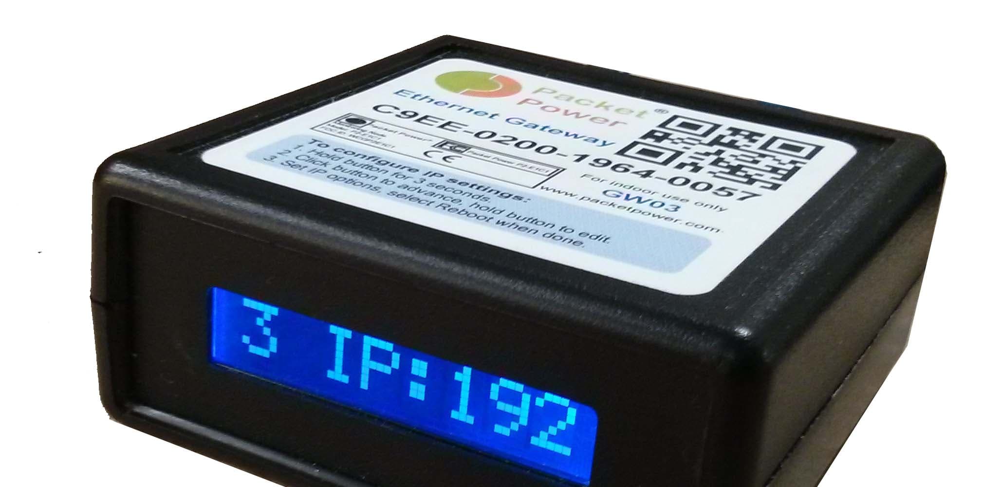
WCGP5EG3
Feb 01, 2015Ethernet Gateway
Equipment Class
DSS - Part 15 Spread Spectrum Transmitter