WG8CSC600ERRemote Control of Amplified Emergency Response Phone
Clearsounds Communications Inc.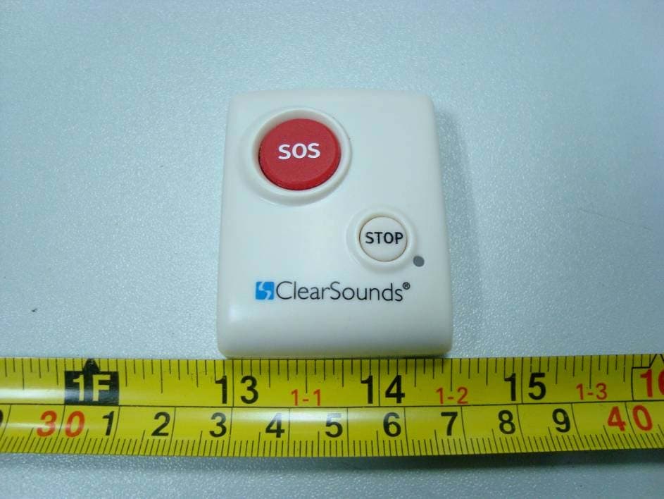
Click to zoom
Application Details
- Equipment Class
- DXX - Part 15 Low Power Communication Device Transmitter
- Date of Grant
- May 02, 2011
- Application Purpose
- Original Equipment
- Date of Application
- May 02, 2011
- Equipment Note
- Remote Control of Amplified Emergency Response Phone
- Frequency Range
- 915.20000000 - 915.20000000
- Country
- United States
Documents & Files
Document Text
Text extracted from the exhibit documents filed with the FCC. Open a document above to read the original.
Users Manual
USER'S MANUAL CSC600ER; XL-2055ER FEATURE LIST. SAFETY INSTRUCTIONS LOCATION OF CONTROLS FUNCTION OPERATION RECEIVING CALL RECORDS CALL ID ON CALL WAITING AMPLIFY FEATURE ............................. ........................ .............................. ...................... ........................... ....................... .............................. SET TIME ................................. SET PHONE................................ SET SOS.................................. ..................... .................. .................. ... ......... ........ .................... ..... .................... ...... PHONE BOOK SETTING UP BASIC FUNCTION REVIEWING DISPLAY MESSAGES CALLER ID SYSTEM OPERATION TROUBLESHOOTING TABLE OF CONTENTS 1 2 3 5 8 11 11 13 13 18 18 20 22 23 24 15 2. Theswitch will be set to theposition and the volume will be set to middle at factory. 3. Please adjust the volume to your necessary. Too loud volume may hurt your ear. We recommend you first move theswitch to the position. OFF OFF Using your Amplified Phone with hearing aids Your phone can be used with hearing aids equipped with a telecoil (T- coil). Adjust your hearing aid "T-switch" to the "T" position. Make sure to hold the handset close to your hearing aid. CAUTION:This telephone can produce very high (loud) sound levels. Repeated incremental exposure to amplification levels greater than 18 dB may be harmful to people without hearing loss. Always adjust the volume control to the minimum setting after using the phone. 25 1. FSK+DTMF dual system caller ID 2. Stores up to 99 incoming calls name & number, date & time 3. Stores up to 30 outgoing calls number 4. Stores up to 99 names & numbers in phone book 5. LCD display calling name & number 6. Call back function 7. Delete individual or all records 8. Real time clock (Set time) 9. NEW call/ Message waiting LED indicator 10. Languages selection 11. 6 one-touch memories 12. 6 SOS numbers auto-dialing 13. SOS message recording 14. Battery low indicator 15. Last number redial 16. Flash time setting 17. Dialing mode setting 18. Speakerphone 19 . Timer . Caller ID on call waiting 20. LCD blue back light 21 FEATURE LIST 1 24 AMPLIFY FEATURE Receiver Voice Tone ONOFF ON TONE AMP OFF AMP The unit provides extra amplification in the tone frequency range you need to boost. You can identify the range follow these steps: First, move theswitch on the rear of the unit toorposition to turn the function on or off. See Figure1. Then: 1. If you move theswitch to position, each time you use the phone, the amplifier turns on automatically, then you can adjust the tone frequency range while on a call by moving thecontrol. See Figure2. But if necessary, you can press the button to temporarily turn on or off the amplifier during a call. See Figure3. 2. If you move theswitch to position, each time you use the phone, the amplifier turns off automatically. But if necessary, you can press the button to temporarily turn on or off the amplifier during a call. See Figure3. OFF ONOFFON Figure1 Figure2 Figure3 NOTES: AMP1. When the amplifier turns on, the red indicator lamp near the button will be bright. To reduce the risk of fire, electrical shock, and injury, please follow these basic safety precautions before you use this equipment. 1. Carefully read the instructions in this manual. 2. Follow all warnings and instructions marked on the unit. 3. When cleaning, unplug the telephone jack from the wall outlet. Use a damp cloth.use liquid or aerosol cleaners. 4. Do not use this equipment near water eg, near a kitchen sink, bathtub, washbowl, laundry rub, swimming pool or in a wet basement. 5. Install in a protected location. Ensure all lines and cords are away from foot traffic.place objects on the line cord that may cause damage or abrasion. 6. Avoid spilling any liquid on the unit. This may cause internal shorting, fire or shock and is not covered under your warranty. 7. Do not overload wall outlets and extension cords as this can result in the risk of fire or electrical shock. 8. Never push objects of any kind into this telephone as they can touch dangerous voltage points or short out parts that could result in a risk of fire or electrical shock. 9. Take the phone to a qualified technician when it requires repair work or service. To reduce the risk of electrical shock, do not disassemble the telephone. Opening or removing covers can expose you to dangerous voltages or other risks. Incorrect re- assembly can cause electrical shock during subsequent use. 10. Avoid using the telephone during an electrical storm. There can be a slight risk of electrical shock from lightning. 11.use the telephone to report a gas leak, if in the vicinity of the leak. 12.Unplug this telephone from the wall outlet and refer servicing to qualified service personnel under the following conditions: If liquid is spilled into the unit. If the unit is exposed to rain or water. If the unit does not operate normally by following the Operating Instructions. If the unit is dropped or the casing is damaged. If the unit exhibits a distinct change in performance. DO NOT DO NOT DO NOT l l l l l SAFETY INSTRUCTIONS 2 23 If you are have problems with your phone, please check below for helpful hints: Check the line cord. Connect Telephone Cord. Check batteries Call your telephone company to verify that your Caller ID services are active. You may have too many communication devices hooked to a single line. A communication device can be a phone, modem, or facsimile (FAX) machine. Contact your telephone company for help in calculating the limit for your residence or business line. Verify that the Line Cord is plugged in correctly. Verify that the Line Cord connection is correct and tightly secured. Call your telephone company to verify that your caller ID services are active. If you have an answering machine connected to this Phone, ensure that your answering machine is set to answer after at least two rings. You answer the call…
Text truncated - open the document above for the full version.
Block Diagram
12345678 A B C D 87654321 D C B A REV. CHECK DESIGN SCALE FIT DWG NO SHEET OF TITLE JERRY DATE APPROVE 20-Apr-2011 CSC600ER; XL2055ER MCU KEY PAD MSP430F2011PWR Power Supply 3.0V RFIC CC1150 915.2MHZ REMOTE PDF 文件使用 "pdfFactory Pro" 试用版本创建 www.fineprint.cn
External Photos
EXHIBIT B - EUT EXTERNAL PHOTOGRAPHS EUT – Top View EUT – Bottom View
Internal Photos
EXHIBIT C - EUT INTERNAL PHOTOGRAPHS EUT – Cover off View EUT – Mainboard Top View EUT – Mainboard Bottom View Antenna
Operational Description
Circuit Description: The MCU and RF IC are supported by the Power Supply (3.0V). When the keypad has been pressed, the MCU will send a command to the RFIC and it will send out a signal in 915.2MHz.
Schematics
1234 A B C D 4321 D C B A REV. CHECK DESIGN SCALE FIT DWG NO SHEET OF TITLE JERRY DATE APPROVE 20-Apr-2011 CSC600ER; XL2055ER C5 104 VDD R1 56k C15 13pf C16 12pf L6 18nH L7 18nH C10 100pf C12 1.5pf C13 3.3pf C11 100pf C6 104 L4 12nH SCK SO SI GDO0 CSn C8 10nf L5 12nH L1 0R C3 220pf C7 10nf C2220p C1 1U C4 1.5pf SCLK 1 SO (GDO1) 2 DVDD 3 DCOUPL 4 GDO0 8 CSn 9 XOSC_Q1 5 AVDD 6 XOSC_Q2 7 RF_P 10 RF_N 11 AVDD 12 AVDD 13 RBIAS 14 DGUARD 15 SI 16 IC1 CC1150 L3 12nH L2 12nH C9 1pf VCC 1 P1_0 2 P1_1 3 P1_2 4 P1_3 5 P1_4 6 P1_5 7 P1_6 8 P1_7 9 RST 10 TEST 11 XOT 12 XIN 13 VSS 14 U1 MSP430F2011PWR R2 10k R6 10K LED1 LED R3 10K STOP1 SW2SCK SO SI GDO0 CSn 1 2 3 4 CON1 CON4 R5 10k R4 1k 3.3V 1 BATTER VDD C17 10nf ANT1 L8 0R X1 26M EM1 SW2 R7 0R R8 0R S1 1 S2 2 S3 3 S4 4 S5 5 S6 6 U2 AWB478-70 TS? RF-TEST C18 2.7pf 915.2MHZ PDF 文件使用 "pdfFactory Pro" 试用版本创建 www.fineprint.cn
Test Report
Note: This test report is prepared for the customer shown above and for the device described herein. It may not be duplicated or used in part without prior written consent from Bay Area Compliance Laboratories Corp. (Shenzhen). This report must not be used by the customer to claim product certification, approval, or endorsement by NVLAP*, NIST, or any agency of the Federal Government. * This report contains data that are not covered by the NVLAP accreditation and are marked with an asterisk “★” (Rev.2) FCC PART 15.249 MEASUREMENT AND TEST REPORT For ClearSounds Communications, Inc. 1743 Quincy Avenue #155, Naperville, IL 60540, USA FCC ID: WG8CSC600ER Report Type: Original Report Product Type: Remote Control of Amplified Emergency Response Phone Test Engineer: Felix Li Report Number: RSZ10122206 Report Date: 2011-03-01 Reviewed By: Merry Zhao EMC Engineer Prepared By: Bay Area Compliance Laboratories Corp. (Shenzhen) 6/F, the 3rd Phase of WanLi Industrial Building, ShiHua Road, FuTian Free Trade Zone Shenzhen, Guangdong, China Tel: +86-755-33320018 Fax: +86-755-33320008 ClearSounds Communications, Inc. FCC ID: WG8CSC600ER Report No.: RSZ10122206 Page 2 of 12 FCC Part15.249 Test Report TABLE OF CONTENTS GENERAL INFORMATION.......................................................................................................................................3 PRODUCT DESCRIPTION FOR EQUIPMENT UNDER TEST (EUT) .....................................................................................3 OBJECTIVE...................................................................................................................................................................3 RELATED SUBMITTAL(S)/GRANT(S).............................................................................................................................3 TEST METHODOLOGY..................................................................................................................................................3 TEST FACILITY.............................................................................................................................................................3 SYSTEM TEST CONFIGURATION ..........................................................................................................................5 JUSTIFICATION.............................................................................................................................................................5 EQUIPMENT MODIFICATIONS.......................................................................................................................................5 BLOCK DIAGRAM OF TEST SETUP................................................................................................................................5 SUMMARY OF TEST RESULTS ...............................................................................................................................6 FCC §15.203 - ANTENNA REQUIREMENT.............................................................................................................7 APPLICABLE STANDARD..............................................................................................................................................7 ANTENNA CONNECTOR CONSTRUCTION......................................................................................................................7 FCC §15.205, §15.209 & §15.249 - RADIATED EMISSIONS ..................................................................................8 APPLICABLE STANDARD..............................................................................................................................................8 MEASUREMENT UNCERTAINTY....................................................................................................................................8 TEST EQUIPMENT SETUP..............................................................................................................................................8 EUT SETUP..................................................................................................................................................................9 TEST PROCEDURE........................................................................................................................................................9 CORRECTED AMPLITUDE & MARGIN CALCULATION...................................................................................................9 TEST EQUIPMENT LIST AND DETAILS.........................................................................................................................10 TEST RESULTS SUMMARY..........................................................................................................................................10 TEST DATA................................................................................................................................................................10 PRODUCT SIMILARITY DECLARATION LETTER..........................................................................................12 ClearSounds Communications, Inc. FCC ID: WG8CSC600ER Report No.: RSZ10122206 Page 3 of 12 FCC Part15.249 Test Report GENERAL INFORMATION Product Description for Equipment under Test (EUT) The ClearSounds Communications, Inc. ’s product, model CSC600ER (FCC ID: WG8CSC600ER), or the "EUT" as referred to in this report is a remote control of AMPLIFIED EMERGENCY RESPONSE PHONE, which measures approximately: 5.0 cm (L) x 4.0 cm (W) x 1.5 cm (H), rated input voltage: DC 3V lithium battery Note: Our product .AMPLIFIED EMERGENCY RESPONSE PHONE, model CSC600ER and XL-2055ER are electrically identical, the difference between them is just the model name due to marketing purposes, we select CSC600ER to test, which was explained in tha attached declaration letter * All measurement and test data in this report was gathered from production sample seria…
Text truncated - open the document above for the full version.
Test Setup Photos
EXHIBIT D - TEST SETUP PHOTOGRAPHS Radiated Emissions - Front View (Below 1 GHz) Radiated Emissions - Rear View (Below 1 GHz) Radiated Emissions - Front View (Above 1 GHz) Radiated Emissions - Rear View (Above 1 GHz)
Contact Information
Applicant
Michele Ahlman(President)
Test Firm
Bay Area Compliance Laboratory Corp. (Shenzhen)John Chan
Technical Specifications
| # | Rule Parts | Frequency Range | Power Output |
|---|---|---|---|
| 1 | 15C | 915.2 MHz - 915.2 MHz | - |
Other Applications from Clearsounds Communications Inc.
WG8QH2
Feb 09, 2015Bluetooth phone hub system
Equipment Class
DSS - Part 15 Spread Spectrum Transmitter
WG8A500
Apr 29, 2013Amplified Cordless Phone
Equipment Class
PUB - Part 15 Unlicensed PCS Base Station
WG8A400
Apr 21, 2013Amplified Cordless Phone
Equipment Class
PUB - Part 15 Unlicensed PCS Base Station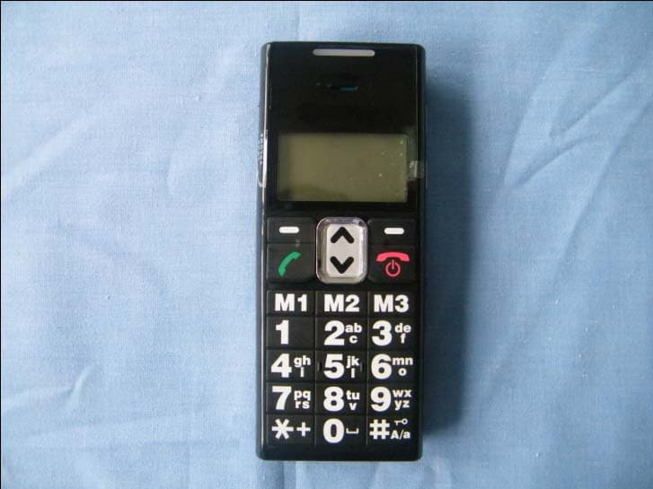
WG8AC100
Nov 15, 2010CLEAR DIGITAL AMPLIFIED CELLULAR HANDSET
Equipment Class
PCE - PCS Licensed Transmitter held to ear