WG8QH2Bluetooth phone hub system
Clearsounds Communications Inc.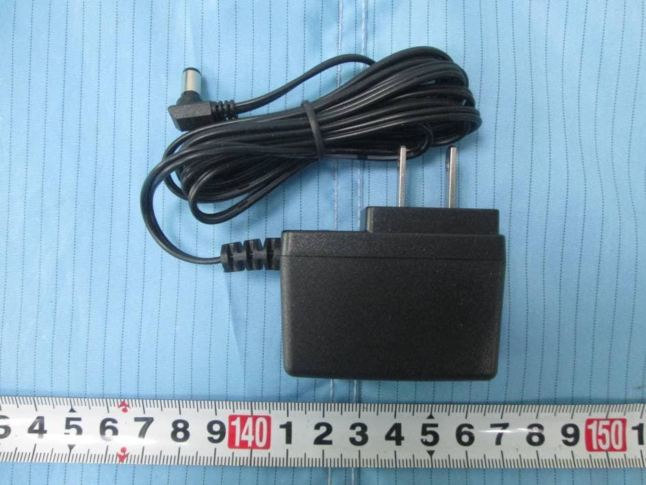
Click to zoom
Application Details
- Equipment Class
- DSS - Part 15 Spread Spectrum Transmitter
- Date of Grant
- Feb 09, 2015
- Application Purpose
- Original Equipment
- Date of Application
- Feb 09, 2015
- Equipment Note
- Bluetooth phone hub system
- Frequency Range
- 2402.00000000 - 2480.00000000
- Country
- United States
Documents & Files
Document Text
Text extracted from the exhibit documents filed with the FCC. Open a document above to read the original.
Users Manual
USER'S MANUAL Portable Telephone Amplifier VOLUME HI LO TONE QH2 This telephone amplifier, which is compatible with Bluetooth headsets, is ideal for use at home, the office or while travelling to help you never miss a word. The unit cannot be used together with any phone where the keypad is located in the handset. Package Contents CHECK THE CONTENTS OF THE BOX Box should contain: l l l l l Bluetooth Amplifier Lifter and Lifter control cord (optional) 2 Telephone line cords AC Power adapter User's manual ? Unplug the handset cord from your telephone base. Insert this cord into the jack marked“”. Plug one side of the short phone cord (included) into the jack marked “”. Plug the other end into the telephone base. Set the compatibility switch to the "4" setting. This provides compatibility for most telephones. Connect the AC power adapter to the power jack (located on the upper left hand side of the unit) and plug the other end into a standard AC wall outlet. Pick up the handset. If you hear a dial tone, IL95 is installed properly. 1. 2. 3. 4. 5. Connection & Installation 1 The off-hook Indicator lights on each time you pick up the handset. Because not all telephone handsets are wired in a standard way, we have provided a 12-position compatibility switch. 1. Place the handset in the cradle. 2. Adjust the switch by turning it one "click" to the next setting. 3. Pick up the handset to listen for a dial tone. 4. Continue this process until you hear a dial tone and the microphone is functional. Once you have located the proper setting, make a note of it in the event it is changed accidentally or you use your amplifier together with a different phone. Telephone Compatibility ! 6 BASE HANDSET LINELIFT 12-position compatibility switch Volume control Tone control Off-hook Indicator MFB Jack for base cord Jack for handset cord If you do not hear a dial tone or the person you are calling cannot hear you, consult the "Telephone Compatibility" section. Bluetooth Indicator 2 Insert the long phone cord (included) into thejack. An optional handset lifter can be inserted in thejack. LINE LIFT 6. 7. Jack for optional lifter Jack for telephone line Jack for base cord VOLUME HI LO TONE After the headset rings, press once to answer the call. You can also answer the call using the headset or answer the call after handset is lifted automatically. Press again. Use the headset to end a call. Handset will be lowered automatically. MFB To end a call: MFB Answering a Call 5 You can adjust the volume level by using the Volume control slide to obtain the desired volume. You can adjust the tone by using the Tone control slide. Adjust the Tone control until you find a position that provides the clearest sound. Volume & Tone Control QH2 QH2 1. Ringing sensor 2. Lifter height adjustment 3. Lifter indicator Lifter 12 3 If the lifted is selected, plug the angle terminal of lifter control cord into the input jack on lifter, plug the straight terminal into the output jack on the base. 3 Place the Bluetooth amplifier within 1 meter away from your Bluetooth headset. Press and holdfor several seconds until the red and blue LED flash alternately. MFB Use your Bluetooth headset to search for devices. For more information about your headset operation, please refer to the user manual of headset. 1. 2. 3. Pairing After the connection is successful, the blue indicator on flashes, 0.1 second on and then 2.9 seconds off. OnQ Q : On Bluetooth headset: To turn onQ , press and holdfor several seconds, then the blue indicator flash once. After that, release the button, the power is on. To turn off , press and holdfor several seconds, the red indicator lights on. After that, release the button, the power is off. MFB MFB Operation Turning On or Off 4 QH2 QH2 QH2 QH2 FCC Caution: Any Changes or modifications not expressly approved by the party responsible for compliance could void the user's authority to operate the equipment. This device complies with part 15 of the FCC Rules. Operation is subject to the following two conditions: (1) This device may not cause harmful interference, and (2) this device must accept any interference received, including interference that may cause undesired operation. FCC Radiation Exposure Statement: This equipment complies with FCC/IC radiation exposure limits set forth for an uncontrolled environment. Note: This equipment has been tested and found to comply with the limits for a Class B digital device, pursuant to part 15 of the FCC Rules. These limits are designed to provide reasonable protection against harmful interference in a residential installation. This equipment generates, uses and can radiate radio frequency energy and, if not installed and used in accordance with the instructions, may cause harmful interference to radio communications. However, there is no guarantee that interference will not occur in a particular installation. If this equipment does cause harmful interference to radio or television reception, which can be determined by turning the equipment off and on, the user is encouraged to try to correct the interference by one or more of the following measures: —Reorient or relocate the receiving antenna. —Increase the separation between the equipment and receiver. —Connect the equipment into an outlet on a circuit different from that to which the receiver is connected. —Consult the dealer or an experienced radio/TV technician for help. IC Warning This device complies with Industry Canada licence-exempt RSS standard(s). Operation is subject to the following two conditions: (1) this device may not cause interference (2) this device must accept any interference, including interference that may cause undesired operation of the device. Le présent appareil est conforme aux CNR d'Industrie Canada applicables aux appareils radio exempts de licence. L'exploitation est autorisée aux deux conditions suivantes : (1) l'appareil ne doit pas produire de brouillage, et (2) l'utilisateur de l'appareil doit acce…
Text truncated - open the document above for the full version.
Cover Letter(s)
Clearsounds Communications Inc. 1743 Quincy Avenue #155 Naperville, IL 60540, Naperville, Illinois, United States Tel: 630.654.9200 Fax: 630.654.9219 FCC Confidential Authorization 2015-2-2 FEDERAL COMMUNICATIONS COMMISSIONS Authorization and Evaluation Division 7435 Oakland Mills Road Columbia, MD 21046 Confidentiality request regarding application for certification of FCC ID: WG8QH2 Pursuant to sections 0.457 and 0.459 of the Commission’s Rules, we hereby request confidential treatment of information accompanying this application as outlined below: Block Diagram--- (Long term) Circuit Description--- (Long term) Detailed Circuit Schematics of EUT--- (Long term) The above materials contain trade secrets and proprietary information not customarily released to the public. The public disclosure of these materials may be harmful to the applicant and provide unjustified benefits to its competitors. The applicant understands that pursuant to Section 0.457 of the Rules, disclosure of this application and all accompanying documentation will not be made before the date of the Grant for this application. Sincerely Yours, Signature: Michele Ahlman President
External Photos
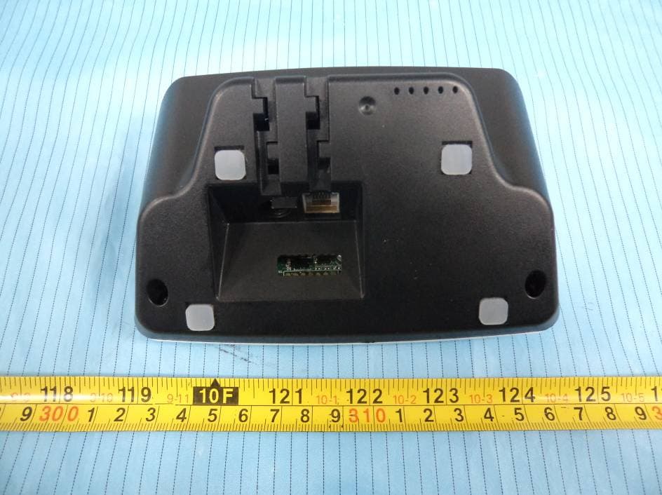
EXHIBIT B - EUT EXTERNAL PHOTOGRAPHS EUT – All View EUT – Front View EUT – Front View EUT – Left View EUT – Right View EUT – Top View EUT – Bottom View EUT – Front View (Lifter) EUT – Front View (Lifter) EUT – Left View (Lifter) EUT – Right View (Lifter) EUT – Top View (Lifter) EUT – Bottom View (Lifter) EUT – Adapter View EUT – Adapter Label View
ID Label/Location Info
EXHIBIT A - FCC ID LABEL AND LOCATION FCC ID Label FCC ID Label Location Information The label shown shall be permanently affixed at a conspicuous location on the device and be readily visible to the user at the time purchase (Labeling requirements per 2.925)
Internal Photos
EXHIBIT C - EUT INTERNAL PHOTOGRAPHS EUT – Cover off View 1 EUT – Cover off View 2 BT Antenna EUT – Main Board 1 Top View EUT – Main Board 1 Bottom View EUT – Main Board 2 Top View EUT – Main Board 2 Bottom View EUT – Cover off View 1 (Lifter) EUT – Cover off View 2 (Lifter) EUT – Main Board Top View (Lifter) EUT – Main Board Bottom View (Lifter)
Test Report
Note: This test report is prepared for the customer shown above and for the equipment described herein. It may not be duplicated or used in part without prior written consent from Bay Area Compliance Laboratories Corp. FCC PART 15.247 TEST REPORT For ClearSounds Communications, Inc. 1743 Quincy Avenue #155 Naperville, IL 60540 U.S.A FCC ID: WG8QH2 Report Type: Original Report Product Type: bluetooth phone hub system Test En gineer: Jay Li Re port Number: RSZ150112002-00B Re port Date: 2015-01-27 Reviewed B y: Jimmy Xiao RF En gineer Prepared By: Bay Area Compliance Laboratories Corp. (Shenzhen) 6/F, the 3rd Phase of WanLi Industrial Building ShiHua Road, FuTian Free Trade Zone Shenzhen, Guangdong, China Tel: +86-755-33320018 Fax: +86-755-33320008 www.baclcorp.com.cn Bay Area Compliance Laboratories Corp. (Shenzhen) Report No.: RSZ150112002-00B FCC Part 15.247 Page 2 of 62 TABLE OF CONTENTS GENERAL INFORMATION ....................................................................................................................................... 4 PRODUCT DESCRIPTION FOR EQUIPMENT UNDER TEST (EUT) ..................................................................................... 4 OBJECTIVE ................................................................................................................................................................... 4 RELATED SUBMITTAL(S)/GRANT(S) ............................................................................................................................. 4 TEST METHODOLOGY .................................................................................................................................................. 4 TEST FACILITY ............................................................................................................................................................. 5 SYSTEM TEST CONFIGURATION .......................................................................................................................... 6 SUPPORT EQUIPMENT LIST AND DETAILS .................................................................................................................... 6 EXTERNAL I/O CABLE .................................................................................................................................................. 6 BLOCK DIAGRAM OF TEST SETUP ................................................................................................................................ 7 SUMMARY OF TEST RESULTS ............................................................................................................................... 8 FCC §15.247 (i) & §2.1093 – RF EXPOSURE ............................................................................................................ 9 APPLICABLE STANDARD .............................................................................................................................................. 9 FCC §15.203 – ANTENNA REQUIREMENT .......................................................................................................... 10 APPLICABLE STANDARD ............................................................................................................................................ 10 ANTENNA CONNECTOR CONSTRUCTION .................................................................................................................... 10 FCC §15.207 (a) – AC LINE CONDUCTED EMISSIONS ..................................................................................... 11 APPLICABLE STANDARD ............................................................................................................................................ 11 MEASUREMENT UNCERTAINTY .................................................................................................................................. 11 EUT SETUP ................................................................................................................................................................ 11 EMI TEST RECEIVER SETUP ....................................................................................................................................... 12 TEST PROCEDURE ...................................................................................................................................................... 12 TEST EQUIPMENT LIST AND DETAILS ......................................................................................................................... 12 CORRECTED FACTOR & MARGIN CALCULATION ....................................................................................................... 12 TEST RESULTS SUMMARY .......................................................................................................................................... 13 TEST DATA ................................................................................................................................................................ 13 FCC §15.205, §15.209 & §15.247(d) – RADIATED EMISSIONS ........................................................................... 16 APPLICABLE STANDARD ............................................................................................................................................ 16 MEASUREMENT UNCERTAINTY .................................................................................................................................. 16 EUT SETUP ................................................................................................................................................................ 16 EMI TEST RECEIVER & SPECTRUM ANALYZER SETUP .............................................................................................. 17 TEST PROCEDURE ...................................................................................................................................................... 17 CORRECTED AMPLITUDE & …
Text truncated - open the document above for the full version.
Test Setup Photos
EXHIBIT D - TEST SETUP PHOTOGRAPHS Conducted Emissions - Front View Conducted Emissions - Side View Radiated Emissions – Front View (30-1000 MHz) Radiated Emissions – Rear View (30-1000 MHz) Radiated Emissions – Front View (1-25 GHz) Radiated Emissions – Rear View (1-25 GHz)
Contact Information
Applicant
Michele Ahlman(President)
Test Firm
Bay Area Compliance Laboratory Corp. (Shenzhen)John Chan
Technical Specifications
| # | Rule Parts | Frequency Range | Power Output |
|---|---|---|---|
| 1 | 15C | 2.40 GHz - 2.48 GHz | 2.60 mW |
Other Applications from Clearsounds Communications Inc.
WG8A500
Apr 29, 2013Amplified Cordless Phone
Equipment Class
PUB - Part 15 Unlicensed PCS Base Station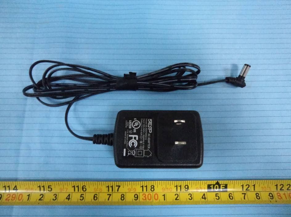
WG8A400
Apr 21, 2013Amplified Cordless Phone
Equipment Class
PUB - Part 15 Unlicensed PCS Base Station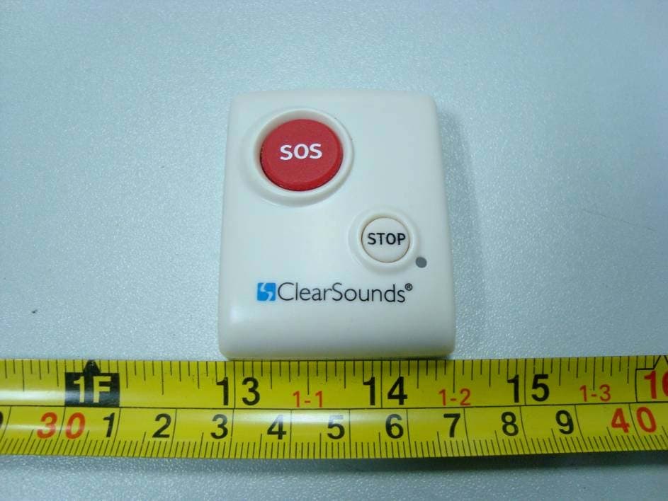
WG8CSC600ER
May 02, 2011Remote Control of Amplified Emergency Response Phone
Equipment Class
DXX - Part 15 Low Power Communication Device Transmitter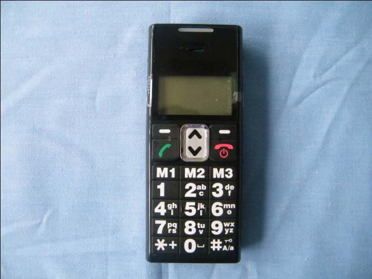
WG8AC100
Nov 15, 2010CLEAR DIGITAL AMPLIFIED CELLULAR HANDSET
Equipment Class
PCE - PCS Licensed Transmitter held to ear