WH2-2611TAWIRELESS CALLING HOST
SHENZHEN CONSTANT ELECTRONICS CO., LTD.
Click to zoom
Application Details
- Equipment Class
- TNB - Licensed Non-Broadcast Station Transmitter
- Date of Grant
- Feb 23, 2014
- Application Purpose
- Original Equipment
- Date of Application
- Feb 19, 2014
- Equipment Note
- WIRELESS CALLING HOST
- Frequency Range
- 465.00000000 - 465.00000000
- Country
- China
Documents & Files
Document Text
Text extracted from the exhibit documents filed with the FCC. Open a document above to read the original.
Users Manual
MMC-2611TA Paging Host User Manual Contents Contents .............................................................................................. 2 1. Summary ......................................................................................... 3 2. Appearance ...................................................................................... 3 3. Parameter ........................................................................................ 4 4. Main Functions ............................................................................... 5 5. Software setup ................................................................................. 7 5.1 Function Introduction ........................................................ 7 5.2 Edit Function ................................................................... 13 5.2.1 Pager Registration ................................................. 13 5.2.2 Palm Registration .............................................. 14 5.2.3 Call Button Registration ....................................... 15 5.2.4 Manual Send Data................................................. 16 5.2.3 Data Download ..................................................... 17 6. Usage ............................................................................................. 18 7. Troubleshoots ................................................................................ 20 8. FCC Important Note ..................................................................... 21 FCC Part 15.19 Warning Statement .......................................... 21 FCC Part 15.21 Warning Statement .......................................... 21 FCC Part 15.105(b) Warning Statement ................................... 22 1. Summary MMC-2611TA works with all MMCall call buttons. It sends alphanumeric message to pager MMC-NC-8E. The functions are: wireless alphanumeric message paging, wireless deletion, duty repage, dispatch, urge dishes, monitoring function, USB data download and program update etc. It is suitable for restaurants, hotels, banks, bars etc. 2. Appearance 2.1 Front Back Power Indicator RX Indicator TX Indicator Field Strength Indicator 3. Parameter 3.1. Parameter Category Parameter Dimension 200mm * 173mm *37mm Power supply 12V/ 1.5A Communication mode and interface type USB(RJ45) Outside Indicator Power supply,RX,TX Configurable transmitting frequencies 462.750MHZ, 462.775MHZ, 462.800MHZ, 462.825MHZ, 462.850MHZ, 462.875MHZ, 462.900MHZ, 462.925MHZ, 465.000MHZ Receiving frequency 433. 500MHZ DC-12V Power Cable Interface RX Antenna Paging No. in cache 40 Repage No. in cache 20 Transmitting power 100mW Sensibility -106dB Antenna Outside BNC Socket Capacity Call button——200 Pager ——20 Palm transmitter——9 Message length 48 digits or letters Signaling standard POCSAG,numeric, english and chinese message supported Temperature -30°C— +65°C Table 3.1 Paging host parameter list 4. Main Functions Main functions are as following: 1. Wireless receiving function. The host can receive the signals from call button and palm transmitter with feature code, and transmit the message to corresponding pager. 2. The pager has to be MMC-NC-8E, which can display numeric and english message. 3. Text preprogrammed function. The paging unit, such as, table, room, bed etc. and the paging category such as call, bill, water can be preprogrammed to the host and related with corresponding call button. When the button is pressed, the pager will display a complete message, such as Table No.5 calls for service. 4. Repage function. Repage times and interval can be setup between the waiter and his directors. If repaging is not finished yet while you cancel it, the message already sent will be automatically deleted. 5. Palm transmitter can be used for dispatching or urging dishes function. 6. Software sending message function. With computer software, the preprogrammed message can be edited to page the programmed pager for interior staff management. 7. Monitoring function. Connected directly with the computer through USB interface, it can monitor the messages from call buttons and palm transmitters for evaluating staff’ working efficiency. If the installation position of the host can not be connected with the computer, the monitor box can be used for the monitoring function. 8. USB data download and upload , program update function available. 5. Software setup Before using the paging host, please first setup the host parameter, pager, call button and palm transmitter. Use the CA software to edit and download the information. The software communication with the paging host is USB mode. Notes: While using, USB can not power on the host, so please connect it with power supply. Otherwise the transmitting and receiving function can not be used. 5.1 Function Introduction The software interface as picture 5.1 shows, mainly includes pager list, palm transmitter list, call button list and manual send data. In the setup column, there are file, system setup, read data, download data. Picture 5.1 TA Software Interface 1、File As picture 5.2 shows, it’s mainly the database operation, including New file, Open, Save as, Delete and Exit. Notes: There should be a database while using the software. For the first time use, it’s necessary to setup a new database, you can choose TA or CA database. The two kinds of database are not compatible with each other. Picture 5.2 File 2. System Setup System setup including initialization, host parameter, program update, call type registration and pager check time. Picture 5.3 System Setup (1)Initialization It will initialize all the host parameters. (2)Host Parameter Host parameter as picture 5.4, room No. Switch is temporarily invalid, the monitor function needs to work with monitoring software, it can be setup as transmitting data, USB passback, net page passback(customization required), among which transmitting data monitor needs to setup pager receiver No., other modes do not need to setup the…
Text truncated - open the document above for the full version.
External Photos
External Photos:
Internal Photos
Internal Photos:
Operational Description
Principle of Work for 2611TA Host The working procedure for TA is: it first receives the information from 433.5Mhz micro-power wireless call button, translate it to the information with indicating significance, the code is POCSAG code format, then send it through the 450.025 MHz ~ 469.975 MHz large power transmitter via antenna to make the relevant mobile receiver to receive the messages. Receiver working procedure: RF wireless signal of the call button which is received from antenna, amplified by high frequency amplifier tube QD1, QD2, to the receiving chip U104, inside which the signal is demodulated, and turns to the wave of TTL power level, via the reshaping of U1 active filter, delivers to single chip U101 for decoding. The field strength is by the receiving chip to send the field strength data to single chip directly driving LED to light on. Transmitter working procedure: single chip U101 encodes those prestored receiver ID code and messages to be sent to POCSAG format, passes them on to transmitting chip U102 with commands method, controls transmitting chip U102 to generate carrier wave and modulation signal, at the same time single chip controls RF power amplifier to power on, after the RF signal is amplified, it will be sent through the antenna. Thus, the relay process from receiving to transmitting is finished. Finally shut off the transmitter and wait for next time transmitting.
Schematics
Principle of Work for 2611TA Host The working procedure for TA is: it first receives the information from 433.5Mhz micro-power wireless call button, translate it to the information with indicating significance, the code is POCSAG code format, then send it through the 450.025 MHz ~ 469.975 MHz large power transmitter via antenna to make the relevant mobile receiver to receive the messages. Receiver working procedure: RF wireless signal of the call button which is received from antenna, amplified by high frequency amplifier tube QD1, QD2, to the receiving chip U104, inside which the signal is demodulated, and turns to the wave of TTL power level, via the reshaping of U1 active filter, delivers to single chip U101 for decoding. The field strength is by the receiving chip to send the field strength data to single chip directly driving LED to light on. Transmitter working procedure: single chip U101 encodes those prestored receiver ID code and messages to be sent to POCSAG format, passes them on to transmitting chip U102 with commands method, controls transmitting chip U102 to generate carrier wave and modulation signal, at the same time single chip controls RF power amplifier to power on, after the RF signal is amplified, it will be sent through the antenna. Thus, the relay process from receiving to transmitting is finished. Finally shut off the transmitter and wait for next time transmitting.
Test Report
FCC PART 90 TEST REPORT APPLICANT SHENZHEN CONSTANT ELECTRONICS CO., LTD. F5, NO. 2 BLDG., EAST BRIGHT INDUSTRY REGION NO. 83 DABAO ROAD BAO'AN 33 DISTRICT SHENZHEN, GUANGDONG FCC ID WH2-2611TA MODEL NUMBER MMC-2611T PRODUCT DESCRIPTION WIRELESS CALLING HOST DATE SAMPLE RECEIVED 10/24/2013 DATE TESTED 11/15/2013 TESTED BY NAM NGUYEN APPROVED BY NAM NGUYEN TIMCO REPORT NO. 1806AUT13TestReport.docx TEST RESULTS PASS FAIL THE ATTACHED REPORT SHALL NOT BE REPRODUCED EXCEPT IN FULL WITHOUT THE WRITTEN APPROVAL OF TIMCO ENGINEERING, INC. 849 NW STATE ROAD 45 NEWBERRY, FL 32669 USA PH: 888.472.2424 OR 352.472.5500 FAX: 352.472.2030 EMAIL: [email protected] HTTP://WWW.TIMCOENGR.COM Certificate # 0955-01 TABLE OF CONTENTS GENERAL REMARKS ................................................................................................... 3 FCC PART RULES ........................................................................................................ 4 TEST ENVIRONMENT .................................................................................................. 4 TEST SETUP SUMMARY .............................................................................................. 4 GENERAL INFORMATION ............................................................................................ 5 EQUIPMENT LIST ........................................................................................................ 6 TEST PROCEDURE ...................................................................................................... 7 RF POWER OUTPUT .................................................................................................... 8 MODULATION CHARACTERISTICS.............................................................................. 9 OTHER MODULATION CHARACTERISTICS ............................................................... 11 OCCUPIED BANDWIDTH ........................................................................................... 12 99% OCCUPIED BANDWIDTH PLOT .......................................................................... 16 SPURIOUS EMISSIONS AT ANTENNA TERMINALS (CONDUCTED)............................ 17 FIELD STRENGTH OF SPURIOUS EMISSIONS .......................................................... 18 FREQUENCY STABILITY ............................................................................................ 19 TRANSIENT FREQUENCY BEHAVIOR ....................................................................... 20 Applicant: SHENZHEN CONSTANT ELECTRONICS CO., LTD. FCC ID: WH2-2611TA Report: S\SHENZHEN CONSTANT\1806AUT13\1806AUT13TestReport.docx Page 2 of 22 GENERAL REMARKS The attached report shall not be reproduced except in full without the written permission of Timco Engineering Inc. Summary The device under test does: fulfill the general approval requirements as identified in this test report not fulfill the general approval requirements as identified in this test report Attestations This equipment has been tested in accordance with the standards identified in this test report. To the best of my knowledge and belief, these tests were performed using the measurement procedures described in this report. All instrumentation and accessories used to test products for compliance to the indicated standards are calibrated regularly in accordance with ISO 17025 requirements. Testing Certificate # 0955-01 I attest that the necessary measurements were made, under my supervision, at: Timco Engineering Inc. 849 NW State Road 45 Newberry, Fl 32669 Authorized Signatory Name: Nam Nguyen Engineering Project Manager Date: 2/5/2014 Applicant: SHENZHEN CONSTANT ELECTRONICS CO., LTD. FCC ID: WH2-2611TA Report: S\SHENZHEN CONSTANT\1806AUT13\1806AUT13TestReport.docx Page 3 of 22 FCC PART RULES Applicable Rule(s) ANSI/TIA 603-C: 2004 CFR 47 Part 90 TEST ENVIRONMENT Test Facility Timco Engineering, Inc. 849 NW State Road 45 Newberry, FL 32669 USA. Test Condition in the laboratory Temperature: 26ºC Relative humidity: 50% TEST SETUP SUMMARY Test Setup Diagram/ Description The DUT was placed in continuous transmit mode and on the turntable per setup per ANSI C63.4: 2003. A test set up explanation is provided in each test section of this report for clarification. Modification to the DUT No modification was made. Applicant: SHENZHEN CONSTANT ELECTRONICS CO., LTD. FCC ID: WH2-2611TA Report: S\SHENZHEN CONSTANT\1806AUT13\1806AUT13TestReport.docx Page 4 of 22 GENERAL INFORMATION DUT Specification DUT Description MMC-2611TA sends alphanumeric message to pager MMC-NC-8E. The functions are: wireless alphanumeric message paging, wireless deletion, duty repage, dispatch, urge dishes, monitoring function, USB data download and program update etc. It is suitable for restaurants, hotels, banks, bars etc. FCC ID WH2-2611TA Model Number MMC-2611T Operating Frequency (462.750, 462.775, 462.800, 462.825, 462.850, 462.875, 462.900, 462.925, and 465.000) MHz No. of Channels 1 Type of Emission 14K0F1D Modulation FSK DUT Power Source 110–120Vac/50– 60Hz DC Power 12V Battery Operated Exclusively Test Item Prototype Pre-Production Production Type of Equipment Fixed Mobile Portable Applicant: SHENZHEN CONSTANT ELECTRONICS CO., LTD. FCC ID: WH2-2611TA Report: S\SHENZHEN CONSTANT\1806AUT13\1806AUT13TestReport.docx Page 5 of 22 EQUIPMENT LIST Device Manufacturer Model Serial Number Cal/Char Date Due Date Analyzer Silver Tower Spectrum Analyzer HP 8566B Opt 462 3552A22064 3638A08608 06/05/13 06/05/15 Analyzer Silver Tower Preamplifier HP 8449B 3008A00372 06/05/13 06/05/15 Analyzer Silver Tower RF Preselector HP 85685A 2926A00983 06/05/13 06/05/15 Analyzer Silver Tower Quasi- Peak Adapter HP 85650A 2811A01175 06/05/13 06/05/15 Power Meter Boonton Electronics 4531 11793 1/9/13 1/9/15 Sensor Boonton 51072A 34647 01/19/13 01/19/15 Antenna: Biconnical Eaton 94455-1 1096 05/10/13 05/10/15 Antenna: Log- Periodic Electro-Metrics LPA-25 1122 05/09/13 05/09/15 Horn Antenna ETS 3117 35923 12/7/11 12/7/13 …
Text truncated - open the document above for the full version.
Contact Information
Applicant
Baoli Wang(General Manager)
Test Firm
Timco Engineering, Inc.Bruno Clavier
Technical Specifications
| # | Rule Parts | Frequency Range | Power Output | Emission | Tolerance |
|---|---|---|---|---|---|
| 9 | 90.203(j)(7) | 465 MHz - 465 MHz | 100.00 mW | 14K0F1D | 0.78 ppm |
Other Applications from SHENZHEN CONSTANT ELECTRONICS CO., LTD.

WH2-2611D
Aug 20, 2020PAGING TRANSCEIVER
Equipment Class
TNB - Licensed Non-Broadcast Station Transmitter
WH2-T10
May 14, 2020PAGING TRANSCEIVER
Equipment Class
TNB - Licensed Non-Broadcast Station Transmitter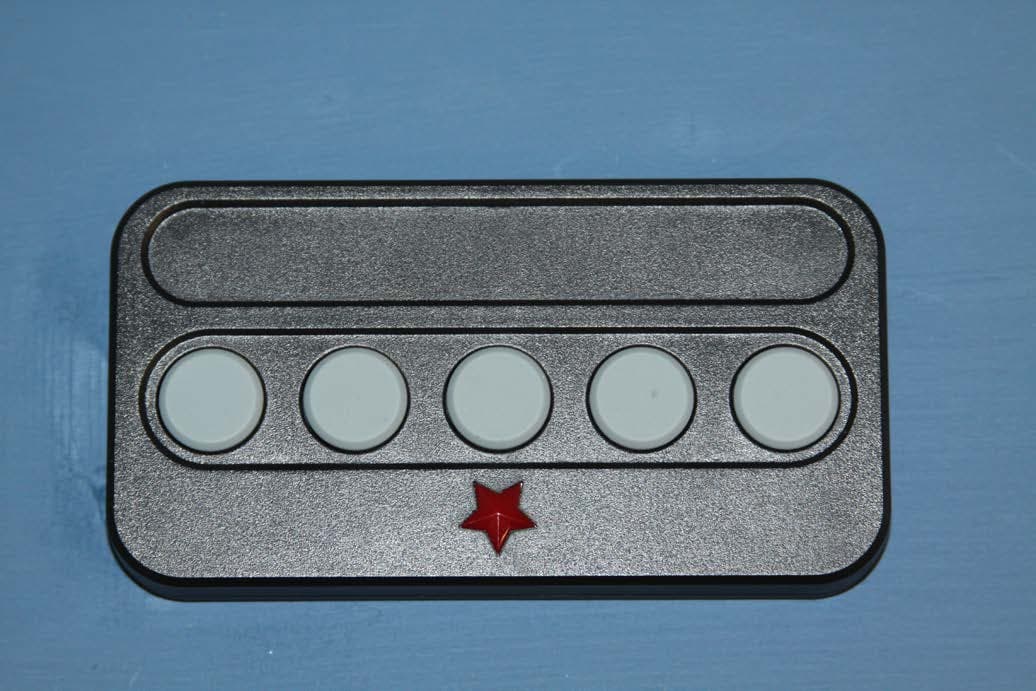
WH2-2610S
Aug 20, 20155 KEY BUTTON TRANSMITTER
Equipment Class
DSC - Part 15 Security/Remote Control Transmitter
WH2-2610D
Jun 07, 2015Remote Transmitter
Equipment Class
DSC - Part 15 Security/Remote Control Transmitter
WH2-T21
Dec 18, 2014Paging Transmitter
Equipment Class
TNB - Licensed Non-Broadcast Station Transmitter