WH3343506Speed monitoring radar
AGD SYSTEMS LTD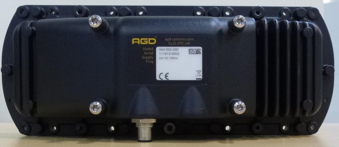
Click to zoom
Application Details
- Equipment Class
- FDS - Part 15 Field Disturbance Sensor
- Date of Grant
- Dec 24, 2025
- Application Purpose
- Original Equipment
- Equipment Note
- Speed monitoring radar
- Frequency Range
- 24125.00000000 - 24125.00000000
- Company
- AGD SYSTEMS LTD
- Country
- United Kingdom
Documents & Files
Document Text
Text extracted from the exhibit documents filed with the FCC. Open a document above to read the original.
Users Manual
✓ beam PRODUCT MANUAL © AGD Systems Limited 2019 Doc. Ref 343 PM ISS1 AGD 343 HIGHWAYS MONITORING RADAR AGD 343 HIGHWAYS MONITORING RADAR AGD 343 HIGHWAYS MONITORING RADAR AGD 343 HIGHWAYS MONITORING RADAR 2 AGD 343 HIGHWAYS MONITORING RADAR AGD 343 HIGHWAYS MONITORING RADAR AGD 343 HIGHWAYS MONITORING RADAR AGD 343 HIGHWAYS MONITORING RADAR INTRODUCTION 2 Product and Technology 2 Key Features 2 Typical Applications 2 Product overview image 2 Installation 3 Installation Information 3 Mounting Location 3 Mounting Location Considerations 3 Physical Installation 4 343 Mounting Bracket Kit 4 Step 1 – Mount bracket to the pole 4 Step 2 – Mount bracket to the radar 4 Step 3 – Mount radar to the pole 5 Electrical Installation 6 Connections 6 343 Power/RS422 Cable Assembly 6 Table of Contents safer, greener, more efficient 3 AGD 343 HIGHWAYS MONITORING RADAR AGD 343 HIGHWAYS MONITORING RADAR AGD 343 HIGHWAYS MONITORING RADAR AGD 343 HIGHWAYS MONITORING RADAR Introduction PRODUCT & TECHNOLOGY KEY FEATURES • Flow monitoring solution for multi-lane real-time data • Traffic Profiling and Incident Detection • Ten lane highway capability • Enforcement grade radar & techniques • Identifies, tracks & measures speed, length, lane/direction of individual targets • Multi-level incident detection mode • Non-intrusive loop replacement • Mounts on existing infrastructure • Simple to install, setup and configure using AGD Align The AGD 343 Highways Monitoring Radar is an easy-to- integrate traffic flow monitoring solution that provides real-time data on multi-lane highways. Designed for traffic profiling and incident detection, the 343 dramatically enhances highways safety, capability and efficiency. AGD’s 343 employs proven enforcement-grade radar & measurement techniques to quantify speed, range and length of passing vehicles. Detailed traffic information - such as, ‘is traffic free-moving, slowing or starting-to- queue?’ - is available in all weather conditions to inform control rooms and allow instant decision making. AGD radar can replace intrusive high-maintenance loops, mounting on existing roadside poles or gantries where it ‘looks’ across the road at 30 degrees. The additional capability to operate at a ≥ 2-metre offset, while maintaining a 6-metre plus mounting height, ensures reliable operation in managed motorway scenarios and ALR (All Lanes Running) schemes. The 343 has been designed to cope with the many difficulties facing international road network installations. 4 AGD 343 HIGHWAYS MONITORING RADAR AGD 343 HIGHWAYS MONITORING RADAR AGD 343 HIGHWAYS MONITORING RADAR AGD 343 HIGHWAYS MONITORING RADAR Introduction TYPICAL APPLICATIONS Multi-Lane Highways Monitoring Radar Caption Caption 5 Flange Mounting Points AGD 343 HIGHWAYS MONITORING RADAR AGD 343 HIGHWAYS MONITORING RADAR AGD 343 HIGHWAYS MONITORING RADAR AGD 343 HIGHWAYS MONITORING RADAR PRODUCT OVERVIEW Power/RS422 Cable Connector Port X4 Fixing Points Introduction safer, greener, more efficient 6 AGD 343 HIGHWAYS MONITORING RADAR AGD 343 HIGHWAYS MONITORING RADAR AGD 343 HIGHWAYS MONITORING RADAR AGD 343 HIGHWAYS MONITORING RADAR INSTALLATION INFORMATION The radar is designed to be mounted to various structures such as a dedicated column, gantry or sign. To install the radar, the following parts will be required: To provide power and communication interfaces the following parts will assist in detector integration: Installation No.Part NoDescriptionNotes 1343-500-000AGD 343 Highways Monitoring Radar 2MS-246343 Mounting Bracket Kit 3CA-310343 Power/RS422 Cable Assembly 4MK343-05Camera Setup Tool(this is removed upon setup) No.Part NoDescriptionNotes 5MK343-01343 Interface Enclosure 6MK343-03343 Interface Enclosure (c/w 24Vdc PSU) 1 4 2 5 3 6 7 AGD 343 HIGHWAYS MONITORING RADAR AGD 343 HIGHWAYS MONITORING RADAR AGD 343 HIGHWAYS MONITORING RADAR AGD 343 HIGHWAYS MONITORING RADAR MOUNTING LOCATION The AGD 343 has been designed to be mounted on a variety of structures, where it looks across the carriageway at 30 degrees to provide highly accurate traffic data. The detector must be mounted at a minimum height of 6m above the carriageway and at an angle of 30 degrees. The AGD align set-up tool assists in accurate set up of the angle. Mounting Location Considerations The detector has been designed to monitor traffic in inter-urban environments while maintaining resilience to external factors, however, care must be taken when choosing a mounting location. Avoid where possible: • Installing the detector where it points toward large reflective surfaces (such as signs, barriers and metal retaining walls) Installation OffsetRecommended Mounting HeightAcceptable Mounting Height 2m6m6m O set: 2 metres Height: 6 metres Setup: AGD Align Visual & Histogram 2 m 30º CONFIGURATION: 6 m O set: 2 metres Height: 6 metres Setup: AGD Align Visual & Histogram 2 m 30º CONFIGURATION: 6 m 8 s DIRECTION OF TRAVEL s DIRECTION OF TRAVEL Pole Pole AGD 343 HIGHWAYS MONITORING RADAR AGD 343 HIGHWAYS MONITORING RADAR AGD 343 HIGHWAYS MONITORING RADAR AGD 343 HIGHWAYS MONITORING RADAR PHYSICAL INSTALLATION 343 Mounting Bracket Kit The AGD 343 bracket mounting kit (part number MS-246) consists of two brackets and all the required fixing hardware. BR-270 is the component of the bracket kit that BR-271 is the component of the bracket kit that fits to the structure you are mounting to. fits to the rear of the radar. Fixing hardware consists of: 7no. M5 x 10mm Torx T20 A2 Stainless Screws 7no. M5 External Shakeproof A2 Stainless Washers Step 1 – Mount bracket to the pole Installation Attach BR-270 to the structure you are mounting too using mounting straps (AGD recommends stainless steel sign banding ½” thick). The position of the bracket should be parallel to the carriageway as in the image below, left. Do not install the bracket as shown in the right hand image. 9 AGD 343 HIGHWAYS MONITORING RADAR AGD 343 HIGHWAYS MONITORING RADAR AGD 343 HIGHWAYS MONITORING RADAR AGD 343 HIGHWAY…
Text truncated - open the document above for the full version.
Attestation Statements
LETTER OF AGENCY 11 November 2025 Element Materials Technology 100 Frobisher Business Park Malvern Worcestershire WR14 1BX UK To Whom It May Concern: We certify that we are not subject to denial of federal benefits, that includes FCC benefits, pursuant to Section 5301 of the Anti-Drug Abuse ACT of 1988, U.S.C. 862. Further, no party, as defined in 47 CFR 1.2002(b), to the application, is subject to denial of federal benefits, that includes FCC benefits. Thank you for your attention to this matter. Sincerely yours, Richard Ellis Compliance Manager AGD Systems
Attestation Statements
Certification designating a U.S. Agent for service of process: As required by section 2.911(d)(7), the applicant must designate a contact located in the United States for purposes of acting as the applicant’s agent for service of process, regardless of whether the applicant is a domestic or foreign entity. An applicant located in the United States may designate itself as the agent for service of process. In either scenario, the designation of the U.S. agent for service of process should be provided as an attachment to the equipment authorization application. The applicant must provide a written certification, which must: i. Be signed by both the applicant and designated agent for service of process, if the agent is different from the applicant. ii. Acknowledge the applicant’s consent and the designated agent’s obligation to accept service of process. iii. Provide a physical U.S. address and email for the designated agent. iv. Acknowledge the applicant’s acceptance to maintain an agent for no less than one year after the grantee has terminated all marketing and importation or the conclusion of any Commission-related proceeding involving the equipment. Unofficial information provided by FCC personnel on February 14, 2023, via the monthly call with the TCB Council: The Agent for Process of Service: • cannot be a TCB or affiliated with a TCB (e.g. could not be a person who works for a TCB or a company that owns or is owned by the TCB) • cannot be a [FCC recognised] Lab or affiliated with a test lab (e.g. could not be a person who works for a Lab or a company that owns or is owned by the Lab) • Agent can be Individual Entity or a Company Entity • Agent Entity must be located in US, US address/phone • Entity acting as Agent must have FRN (best practice, put FRN on Agent Letter) • Agent letter does not have to be FCC ID specific, can be general Agent for Grantee For devices being marketed or for which marketing has ceased for less than 1 year, if the Agent for Process of Service changes, then for every TC Number the TCB must request the FCC to put application into Audit Mode and Agent Letter needs to be updated (superseded). NOTE: The U.S. Agent for Service of Process should not be confused with the authorized agent used for signing the 731 form, other cover letters within the application, and/or the agent who may interface with the TCB. U.S. Agent Designation for Service of Process ATTENTION: Federal Communications Commission Authorization and Evaluation Division 7435 Oakland Mills Road Columbia, MD 21046 USA REGARDING: FCC Certification – Section 2.911(d)(7) Information Designated U.S. Agent Company Name: Approve-IT, Inc. Contact Name: Nathan Grinager Street Address: 8011 34 th Ave South, Suite 342 City/Province/Zip: Bloomington, MN 55425 Telephone No: 651-247-1678 Email: [email protected] FRN #: 0027533835 This letter is to confirm that we (“the Designated U.S. Agent) have accepted the responsibility to act as the Designated U.S. Agent for Service of Process as required by section 47 CFR 2.911(d)(7) on behalf of the Applicant noted below. U.S. Agent Signature: Date: December 16, 2025 Signed by (Printed Name/Title): Nathan Grinager / Co-President The Applicant confirms its explicit consent and acknowledges that they must maintain an agent for no less than one year after terminating all marketing and importation OR the conclusion of any Commission-related proceeding involving the equipment. The applicant further acknowledges their responsibility to inform the FCC whenever the Designated U.S. Agent information above changes. Applicant Company name: AGD Systems Ltd Grantee FRN: 0017935768 FCC ID: WH3343506 Contact Name: Richard Ellis Street Address: White Lion House, Gloucester Road City/Province/Zip: Cheltenham, GL51 0TF Telephone No:- Email: [email protected] Applicant Signature: Date: 12/16/25 Signed by (Printed Name/Title):Richard Ellis/Compliance Manager
Attestation Statements
Date: 2025-11-12 Federal Communications Commission Authorization and Evaluation Division 7435 Oakland Mills Road Columbia, Maryland 21046 Re: Attestation regarding ‘covered’ equipment and the Covered List FCC ID: WH3343506 To whom it may concern, Per 2.911(d)(5)(i), AGD Systems certifies that the equipment for which authorization is sought is not “covered” equipment prohibited from receiving an equipment authorization pursuant to section 2.903 of the FCC rules. Per 2.911(d)(5)(ii) , AGD Systems certifies that, as of the date of the filing of the application, the applicant is not identified on the Covered List as an entity producing “covered” equipment. Per KDB 986446 D01 v03 section B, 2a, AGD Systems certifies that the equipment for this application does not contain Kaspersky cybersecurity or anti-virus software. Sincerely, Richard Ellis Compliance Manager AGD Systems
Cover Letter(s)
Date 11/12/25 Federal Communications Commission Authorization and Evaluation Division 7435 Oakland Mills Road Columbia, Maryland 21046 Re: Request for confidentiality FCC ID: WH3343506 To whom it may concern, We hereby respectfully request that under the provision of 47 CFR 0.459 and 0.457(d) the documents listed below and attached with this application for certification be provided with confidential status. • Bill of Materials 343-506-000 • 2018-11-20_IVQ-980_980_2_Bestückung • 2019-11-19_IVQ-980_2_Schaltplan • 343 operational description • 343 Block Diagram • BLP466-5 gerber • BLP466-5 schm • BOM_IVQ-980 • Bottom Assembly • CB-319-11 • BLP466-5-1 parts list • Top Assembly Any exhibit / information for which we have requested confidentiality, but which may not be accorded such treatment by the FCC, should be returned to us. The documents listed above contain trade secrets that are treated as confidential by us. Substantial competitive harm to us could result should they be made available to the public. Sincerely yours, Richard Ellis Compliance Manager AGD Systems
External Photos
Figure 1 343 Front Figure 2 343 Right Side Figure 3 343 Rear Figure 4 343 Left Side Figure 5 343 Top Figure 6 343 Bottom
ID Label/Location Info
AGD 343 Label Placement: The Regulatory label is made up of 2 parts: 1) LB-223 2) Serial number label LB-041P The 2 parts when combined will look as below The above label will be applied to the Unit in the position shown below The Following Label will be attached to the Packaging: The labels are applied as per the build instruction
Internal Photos
Figure 1 CB 319/BL 466 Top View Figure 2 CB 319/BL 466 Bottom View Figure 3 MC-134/IVQ-980 Antenna view Figure 4 MC-134/IVQ-980 Bottom view Figure 5 IVQ-980 Internal PCB Figure 6 IVQ-980 Internal shield Figure 7 CB-319 Mounted on IVQ-980 Figure 8 CB-319 Connection to external connector Figure 9 CB-319 & IVQ-980 mounted in rear Enclosure
RF Exposure Info
Report Number: TRA-065980-47-03A Page 38 of 40 16 RF Exposure OVERVIEW Section 1.3 of KDB 44798 D04 v01 states that, “Under the new rules, all radio services and operations are subject to Routine Evaluation [§§ 1.1307(b)(1), 2.1033(f), etc.], unless shown to qualify under the exemptions provided in the rules and OET Lab policies for equipment authorization.” The glossary of KDB 447498 D04 v01 specifies that an exempt RF device is defined “solely from the obligation to perform a routine environmental evaluation to demonstrate compliance with the RF exposure limits in § 1.1310; it is not exemption from the equipment authorization procedures described in 47 CFR Part 2, not exemption from general obligations of compliance with the RF exposure limits in § 1.1310 of this chapter, and not exemption from determination of whether there is no significant effect on the quality of the human environment under § 1.1306.” Compliance with the exemption criteria defined in 1.1307(b) confirm compliance with the limits in § 1.1310. COMPLIANCE WITH FCC 1.1310 Per 1.1307(b)(3), (i) For single RF sources (i.e., any single fixed RF source, mobile device, or portable device, as defined in paragraph (b)(2) of this section): A single RF source is exempt if: (A) The available maximum time-averaged power is no more than 1 mW, regardless of separation distance. This exemption may not be used in conjunction with other exemption criteria other than those in paragraph (b)(3)(ii)(A) of this section. Medical implant devices may only use this exemption and that in paragraph (b)(3)(ii)(A); (B) Or the available maximum time-averaged power or effective radiated power (ERP), whichever is greater, is less than or equal to the threshold P th (mW) described in the following formula. This method shall only be used at separation distances (cm) from 0.5 cm to 40 cm and at frequencies from 0.3 GHz to 6 GHz (inclusive). P th is given by: 푃 푡ℎ ( 푚푊 ) = { 퐸푅푃 20 푐푚 ( 푑20 푐푚 ⁄ ) 푥 푑≤20 푐푚 퐸푅푃 20 푐푚 20 푐푚 <푑 ≤40 푐푚 Where 푥= − log 10 ( 60 퐸푅푃 20 푐푚 √ 푓 ) 푎푛푑 푓 푖푠 푖푛 퐺퐻푧; And 퐸푅푃 20 푐푚 (푚푊)= { 2040푓0.3 퐺퐻푧 ≤푓 <1.5 퐺퐻푧 30601.5 퐺퐻푧 ≤푓 ≤6 퐺퐻푧 (C) Or using Table 1 and the minimum separation distance (R in meters) from the body of a nearby person for the frequency (f in MHz) at which the source operates, the ERP (watts) is no more than the calculated value prescribed for that frequency. For the exemption in Table 1 to apply, R must be at least λ/2π, where λ is the free-space operating wavelength in meters. If the ERP of a single RF source is not easily obtained, then the available maximum time-averaged power may be used in lieu of ERP if the physical dimensions of the radiating structure(s) do not exceed the electrical length of λ/4 or if the antenna gain is less than that of a half-wave dipole (1.64 linear value). Report Number: TRA-065980-47-03A Page 39 of 40 TABLE 1 TO §1.1307(b)(3)(i)(C)—SINGLE RF SOURCES SUBJECT TO ROUTINE ENVIRONMENTAL EVALUATION RF Source Frequency (MHz) Threshold ERP (watts) 0.3-1.34 1,920 R 2 . 1.34-30 3,450 R 2 /f 2 . 30-300 3.83 R 2 . 300-1,500 0.0128 R 2 f. 1,500-100,000 19.2R 2 . (ii) For multiple RF sources: Multiple RF sources are exempt if: (A) The available maximum time-averaged power of each source is no more than 1 mW and there is a separation distance of two centimeters between any portion of a radiating structure operating and the nearest portion of any other radiating structure in the same device, except if the sum of multiple sources is less than 1 mW during the time-averaging period, in which case they may be treated as a single source (separation is not required). This exemption may not be used in conjunction with other exemption criteria other than those is paragraph (b)(3)(i)(A) of this section. Medical implant devices may only use this exemption and that in paragraph (b)(3)(i)(A). (B) in the case of fixed RF sources operating in the same time-averaging period, or of multiple mobile or portable RF sources within a device operating in the same time averaging period, if the sum of the fractional contributions to the applicable thresholds is less than or equal to 1 as indicated in the following equation. ∑ 푃 푖 푃 푡ℎ,푖 + 푎 푖=1 ∑ 퐸푅푃 푗 퐸푅푃 푡ℎ,푗 +∑ 퐸푣푎푙푢푎푡푒푑 푘 퐸푥푝표푠푢푟푒 퐿푖푚푖푡 푘 ≤1 푐 푘=1 푏 푗=1 Where: a = number of fixed, mobile, or portable RF sources claiming exemption using paragraph (b)(3)(i)(B) of this section for P th , including existing exempt transmitters and those being added. b = number of fixed, mobile, or portable RF sources claiming exemption using paragraph (b)(3)(i)(C) of this section for Threshold ERP, including existing exempt transmitters and those being added. c = number of existing fixed, mobile, or portable RF sources with known evaluation for the specified minimum distance including existing evaluated transmitters. P i = the available maximum time-averaged power or the ERP, whichever is greater, for fixed, mobile, or portable RF source i at a distance between 0.5 cm and 40 cm (inclusive). P th,i = the exemption threshold power (P th ) according to paragraph (b)(3)(i)(B) of this section for fixed, mobile, or portable RF source i. ERP j = the ERP of fixed, mobile, or portable RF source j. ERP th,j = exemption threshold ERP for fixed, mobile, or portable RF source j, at a distance of at least λ/2π according to the applicable formula of paragraph (b)(3)(i)(C) of this section. Evaluated k = the maximum reported SAR or MPE of fixed, mobile, or portable RF source k either in the device or at the transmitter site from an existing evaluation at the location of exposure. Exposure Limit k = either the general population/uncontrolled maximum permissible exposure (MPE) or specific absorption rate (SAR) limit for each fixed, mobile, or portable RF source k, as applicable from §1.1310 Report Number: TRA-065980-47-03A Page 40 of 40 The relationship between EIRP and ERP is: 퐸푅푃 ( 푑퐵푚 ) =퐸퐼푅푃 ( 푑퐵푚 ) −2.14 푑퐵 Where EIRP is the sum of the conducted power (dBm) and the antenna gain (dBi). ASSESSMENT The exem…
Text truncated - open the document above for the full version.
Test Report
Report on the Radio Testing For AGD Systems Ltd on 343 Report no. TRA-065980-47-03A 23rd December 2025 REPORT ON THE RADIO TESTING OF A AGD Systems Ltd 343 WITH RESPECT TO SPECIFICATION FCC 47CFR 15.245 TEST DATE: 8 th October-31 st October 2025 Tested by: S Garwell/S Hodgkinson Radio Test Engineer Written by: p.p. S Hodgkinson Radio Test Engineer Approved by: J Charters Lab Manager Date: 23rd December 2025 Disclaimers: [1] THIS DOCUMENT MAY BE REPRODUCED ONLY IN ITS ENTIRETY AND WITHOUT CHANGE [2] THE RESULTS CONTAINED IN THIS DOCUMENT RELATE ONLY TO THE ITEM(S) TESTED Report Number: TRA-065980-47-03A Issue: A Report Number: TRA-065980-47-03A Page 3 of 40 1 Revision Record Issue Issue Date Revision History A 23rd December 2025 Original Report Number: TRA-065980-47-03A Page 4 of 40 2 Summary TEST REPORT NUMBER: TRA-0659803-47-03A WORKS ORDER NUMBER: TRA-065980-02 PURPOSE OF TEST: USA: Testing of radio frequency equipment per the relevant authorization procedure of chapter 47 of CFR (code of federal regulations) Part 2, subpart J TEST SPECIFICATION: 47CFR15 EQUIPMENT UNDER TEST (EUT): 343 FCC IDENTIFIER: WH3343506 MANUFACTURER/AGENT: AGD Systems Ltd ADDRESS: White Lion House Gloucester Road Staverton Cheltenham Gloucestershire GL51 0TF United Kingdom CLIENT CONTACT : Richard Ellis 01452 688187 [email protected] ORDER NUMBER: 411775 TEST DATE: 8 th October-31 st October 2025 TESTED BY: S Garwell/S Hodgkinson Element Report Number: TRA-065980-47-03A Page 5 of 40 2.1 Test Summary Test Method and Description Requirement Clause 47CFR15 Applicable to this equipment Result Radiated spurious emissions 15.245(b) Pass AC power line conducted emissions 15.207 Pass Occupied bandwidth 15.215(c) Pass Field strength of fundamental 15.245(b) Pass notes: The results contained in this report relate only to the items tested, in the condition at time of test, and were obtained in the period between the date of initial receipt of samples and the date of issue of the report. The apparatus was set up and exercised using the configurations, modes of operation and arrangements defined in this report only. Any modifications made are identified in Section 8 of this report. Particular operating modes, apparatus monitoring methods and performance criteria required by the standards tested to have been performed except where identified in Section 5.2 of this test report (Deviations from Test Standards). The decision rule for compliance is not inherent within this specification and compliance is based on the customer requesting a simple acceptance rule based on understanding and acceptance of Elements Measurement Uncertainty values. Graphical Representation of a Pass / Fail Binary Statement - Simple Acceptance ● = Measured value U = 95 % expanded measurement uncertainty Upper Specification Nominal Lower Specification Statement of Conformance Pass Pass Fail Fail U Report Number: TRA-065980-47-03A Page 6 of 40 3 Contents 1 Revision Record .............................................................................................................................................. 3 2 Summary ......................................................................................................................................................... 4 2.1 Test Summary ......................................................................................................................................... 5 3 Contents .......................................................................................................................................................... 6 4 Introduction ..................................................................................................................................................... 7 5 Test Specifications .......................................................................................................................................... 8 5.1 Normative References ............................................................................................................................. 8 5.2 Deviations from Test Standards .............................................................................................................. 8 6 Glossary of Terms ........................................................................................................................................... 9 7 Equipment under Test ................................................................................................................................... 10 7.1 EUT Identification .................................................................................................................................. 10 7.2 System Equipment ................................................................................................................................ 10 7.3 EUT Mode of Operation ........................................................................................................................ 10 7.4 EUT Radio Parameters ......................................................................................................................... 10 7.5 EUT Description .................................................................................................................................... 10 8 Modifications ................................................................................................................................................. 11 9 EUT Test Setup ............................................................................................................................................. 12 9.1 Block Diagram ....................................................................................................................................... 12 9.2 EUT Test Setup Photographs ............................................................................................................... 12 9.3 Measurement software ..................…
Text truncated - open the document above for the full version.
Contact Information
Applicant
Richard Ellis(MR)
[email protected]Fax: +44 (0) 1452854213
Technical Contact
Approve-IT, Inc.Nathan Grinager
8011 34th Ave South, Suite 342 · Bloomington, Minnesota, 55425 · United States
Test Firm
Element Materials Technology Warwick LtdNeil Roche
[email protected]Fax: 44 1926 478479
Technical Specifications
| # | Rule Parts | Frequency Range | Power Output |
|---|---|---|---|
| 1 | 15.245 | 24.13 GHz - 24.13 GHz | - |
Other Applications from AGD SYSTEMS LTD
WH3326505
May 21, 2020Pedestrian On-Crossing Detector
Equipment Class
FDS - Part 15 Field Disturbance Sensor
WH3342100
Feb 25, 2013AGD342-100-xxx Speed Enforcement Ranging Radar
Equipment Class
FDS - Part 15 Field Disturbance Sensor
WH3AGD315-207
May 17, 2011AGD 315-207-000 Microwave Vehicle Detector
Equipment Class
FDS - Part 15 Field Disturbance Sensor