WIWTT1000Badge Reader
e-DATA GmbH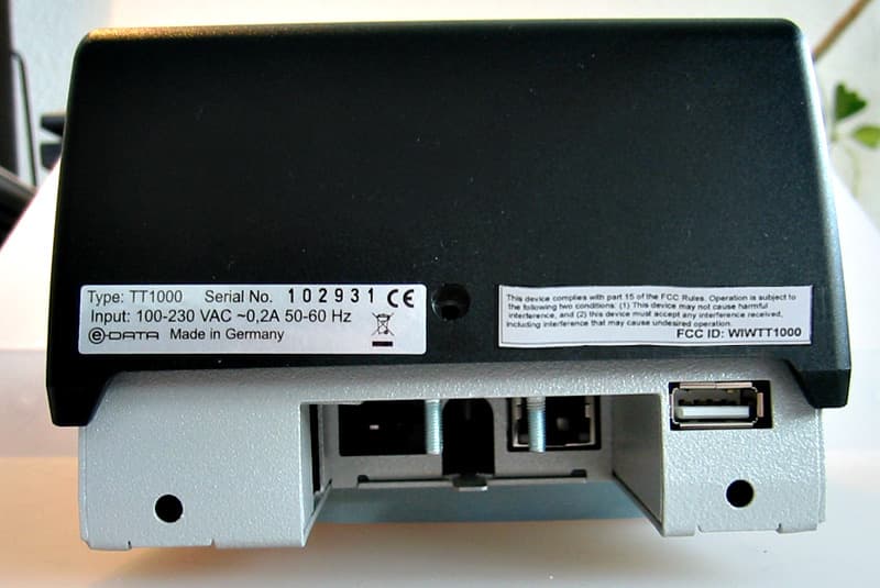
Click to zoom
Application Details
- Equipment Class
- DXX - Part 15 Low Power Communication Device Transmitter
- Date of Grant
- Mar 01, 2010
- Application Purpose
- Original Equipment
- Date of Application
- Mar 01, 2010
- Equipment Note
- Badge Reader
- Frequency Range
- 13.56000000 - 13.56000000
- Company
- e-DATA GmbH
- Country
- Germany
Documents & Files
Document Text
Text extracted from the exhibit documents filed with the FCC. Open a document above to read the original.
Users Manual
01.2009 Version 1.31-1 Installation and Maintenance TT1000 TT3000 TT4000 Version 1.3 e-DATA GmbH 1-201.2009 Version 1.3 1Usage1-3 1.1Protection Class and Protection Type ................................... 1-3 1.2Safety Measures ................................................................... 1-3 1.3Before Commissioning .......................................................... 1-3 1.4Operation .............................................................................. 1-3 1.4.1Installation and Service ......................................................... 1-4 1.5CE Conformance .................................................................. 1-4 1.6FCC ...................................................................................... 1-5 2Installation2-6 2.1Parts included ....................................................................... 2-6 2.2Installation conditions............................................................ 2-6 2.3Cable laying .......................................................................... 2-7 2.4Device connection variants ................................................... 2-7 2.5Mounting and connecting the TT3 device............................ 2-10 2.6Shutdown mechanism......................................................... 2-12 2.6.1Web-Interface for Administration ......................................... 2-13 2.7Cleaning the device ............................................................ 2-13 2.8Repairs ............................................................................... 2-14 2.9Guarantee........................................................................... 2-14 01.2009 Version 1.31-3 1 Usage The device may only be used under those conditions and for those purposes for which it has been designed. 1.1 Protection Class and Protection Type The device conforms to the conditions of protection class IP30. The device should only be run inside buildings. 1.2 Safety Measures This device has been built according to the state-of-the-art and the recognized technical safety rules and has left our works in perfect condition. Improper handling and operation outside the specified conditions can result in dangers due to electrical current. This can endanger the lives of persons and damage the machine. 1.3 Before Commissioning Check the device for visible damage during transportation or improper storage. Do not commission a damaged device! The device may only be operated with AC voltage 110 to 240V AC 50 to 60Hz. 1.4 Operation Do not subject the device to any mechanical stresses such as impacts, violent shaking or heavy loads. Impacts and shaking can damage the electronics. 1-401.2009 Version 1.3 1.4.1 Installation and Service The device should only be opened by suitably trained technical personnel. Before opening disconnect the device from the power source. You should carry out repairs only in consultation with e-DATA GmbH 1.5 CE Conformance Safety requirements This device is manufactured according to the safety requirements of EN 60950. Interference resistance This device complies to the interference resistance criteria according to EN 55024 x Emitted interference This terminal complies to the emitted interference criteria according to: EN 55022 EN 61000 Emitted interference TT1000 EN 55022 EN 61000 CSA 60950 und FCC 01.2009 Version 1.31-5 1.6 FCC This equipment complies with Part 15 of the FCC rules. Any changes or modifications not expressly approved by the Manufacturer could void the user's authority to operate the equipment. This device complies with Part 15 of the FCC rules subject to thefollowing two conditions: 1. This device may not cause harmful interference 2. This device must accept all interference received, including interference that may cause undesired operation. NOTE: This equipment has been tested and found to comply with the limits for a Class A digital device, pursuant to part 15 of the FCC Rules. These limits are designed to provide reasonable protection against harmful interference when the equipment is operated in a commercial environment. This equipment generates, uses, and can radiate radio frequency energy and, if not installed and used in accordance with the instruction manual, may cause harmful interference to radio communications. Operation of this equipment in a residential area is likely to cause harmful interference in which case the user will be required to correct the interference at his own expense. 2-601.2009 Version 1.3 2 Installation Danger of current shocks! The device should only be opened by suitably trained technical personnel. 2.1 Parts included x1 device for Time & Attendance x1 wall mounting kit 2.2 Installation conditions xSurface wall installation with hidden screws. The cables are fed on the back of the device under the plaster or as an alternative from the bottom of the device. xData lines to the higher or lower-level device are provided by the customer. xIf using the connection variant 2, i.e. connection cables from the back,please ensure, that the in-wall connector is located at the right position. See figure 5.3 The power supply is provided by the customer. Security advice xTo limit the input voltage of the device to overvoltage category II the customer provides an appropriate overvoltage protection unit! xAlso an appropriate, easily accessible separator for the power circuit is provided by the customer. xThe power supply provided by the customer must use solid conductors or a build-in power cable and a power outlet! xPossibly national regulations apply. Network connections are only allowed within the same building! 01.2009 Version 1.32-7 Before mounting the device to the wall, please check the following pre-conditions: Clearance Enough clearance must be available for mounting the device (see casing dimensions in fig. 4.1). Make sure enough clearance is available for the cables that might be fed from the back. 2.3 Cable laying General hints Do not lay the data lines in parall…
Text truncated - open the document above for the full version.
Users Manual
Terminal Configuration Manual TT1000 Series 06.2009 Version 1.11-1 Terminal Configuration Manual TT1000 Series Version 1.1 e-DATA GmbH Terminal Configuration Manual TT1000 Series 1-206.2009 Version 1.1 e-DATA GmbH Mollenbachstrasse 19 D-71229 Leonberg Germany www.e-data.com Phone +49 7152 93979-0 Fax +49 7152 93979-50 Terminal Configuration Manual TT1000 Series Version 1.1 Copyright 2009 e-DATA GmbH This manual is protected. Reproduction or translation of the manual or its transmission on other electronic media, even in extract form, is only allowed with the express written permis sion ofe-DATA GmbH. e-DATA GmbHreserves the right to make changes to the In- stallation and Maintenance manual without prior notice. e-DATA GmbHdoes not accept any liability whatever for direct and indirect damage, espe cially loss of data, that result from the usage of the TT1000 Series terminal, the software or the man- ual! Terminal Configuration Manual TT1000 Series 06.2009 Version 1.11-3 Terminal Configuration Manual TT1000 Series 1-406.2009 Version 1.1 1 Content 1Content1-4 2Terminal specification2-6 2.1Feature overview .................................................................. 2-6 3Setting up the TT1000 Series terminal3-8 4Keyboard assignment4-10 4.1Key assignment - reduced keyboard (11 keys).................... 4-10 5Terminal start-up5-11 5.1Using the start-up prompts .................................................. 5-11 5.2Changing the start-up prompts............................................ 5-13 6Parameter description6-15 6.1General parameter description............................................ 6-15 6.1.1How to display the web interface......................................... 6-15 6.1.2Configuration parameters.................................................... 6-16 6.1.3Configuration parameter groups – overview........................ 6-17 6.2Detailed parameter description ........................................... 6-17 6.2.1System configuration........................................................... 6-18 6.2.2Linux parameters ................................................................ 6-26 6.2.3Network parameters............................................................ 6-28 6.2.4Readers .............................................................................. 6-30 6.2.5Peripheral devices .............................................................. 6-33 6.2.6Communications parameters .............................................. 6-36 6.3Application parameters ....................................................... 6-42 6.3.1Application parameter groups - overview ............................ 6-42 6.3.2Resend bookings parameters ............................................. 6-43 6.3.3Reports parameters ............................................................ 6-44 Terminal Configuration Manual TT1000 Series 06.2009 Version 1.11-5 7Fingerprint terminals in practice7-46 7.1Introduction..........................................................................7-46 7.2Enrollment process ..............................................................7-46 7.2.1Calling the main menu .........................................................7-46 7.2.2Enroll ...................................................................................7-47 7.2.3Delete user ..........................................................................7-47 7.2.4Delete all..............................................................................7-47 8Appendix for Developers8-48 8.1Linux commands..................................................................8-48 8.1.1Connecting to the terminal ...................................................8-48 8.1.2Basic Linux commands ........................................................8-48 8.2Web interface page Database..............................................8-53 8.3Web interface page Java Statistics ......................................8-55 Terminal Configuration Manual TT1000 Series 2-606.2009 Version 1.1 2 Terminal specification 2.1 Feature overview x400 / 600 MHz Xscale CPU with Linux OS and JAVA VM xMonochrome graphics LCD with 128x64 pixels / 8x20 char- acters, adjustable brightness xCustom keyboard layout with 11 keys x3kHz / 94dB Buzzer for acoustic feedback, two volumes xLight bar with 6 RGB-LEDs, eight base colors, adjustable brightness xPower-supply: mains operated 100 to 230 VAC. Optionally available PoE 802.3af or 10 to 26 VDC socket xEthernet (TCP/IP) 100 Mbps xOptional integrated modem xSupport of all leading reader technologies (Legic, HID, Mi- fare, I- Code, EM, Hitag and ISO 15693, Magnetic stripe and Barcode, Fingerprint) xTwo optical sensors for sabotage detection xPassive Infrared (PIR) motion sensor xUSB 1.1 Full speed Terminal Configuration Manual TT1000 Series 06.2009 Version 1.12-7 FCC Notes This equipment complies with Part 15 of the FCC rules. Any changes ormodifications not expressly approved by the manufacturer could void the user's authority to operate the equipment. This device complies with Part 15 of the FCC rules subject to the following two conditions: This device may not cause harmful interference This device must accept all interference received, including interference that may cause undesired operation. NOTE: This equipment has been tested and found to comply with the limits for a Class A digital device, pursuant to part 15 of the FCC Rules. These limits are designed to provide reasonable protection against harmful interference when the equipment is operated in a commercial environment. This equipment generates, uses, and can radiate radio frequency energy and, if not installed and used in accordance with the instruction manual, may cause harmful interference to radio communications. Operation of this equipment in a residential area is likely to cause harmful interference in which case the user will be required to correct the interference at his own ex- pense. Terminal Configuration Manual TT1000 …
Text truncated - open the document above for the full version.
Cover Letter(s)
e-DATA GmbH Mollenbachstr.19 71229 Leonberg Tel +49 7152 93979-0 Fax +49 7152 93979-50 Mail [email protected] www.e-data.com ® ® ® T I M E L I N K N E X T O R N E X R O N Geschäftsführer: Dietmar Zappel Bankverbindung: Baden-Württembergische Bank BLZ 60050101 Konto-Nr. 8961086 Ust.Id.Nr. DE229038456 Steuer Nr. 70070/11422 HRB253180 Amtsgericht Stuttgart Registergericht WEEE-Reg.-Nr. DE29902720
Operational Description
e-DATA GmbH Mollenbachstr.19 71229 Leonberg Tel +49 7152 93979-0 Fax +49 7152 93979-50 Mail [email protected] www.e-data.com ® ® ® T I M E L I N K N E X T O R N E X R O N Geschäftsführer: Dietmar Zappel Bankverbindung: Baden-Württembergische Bank BLZ 60050101 Konto-Nr. 8961086 Ust.Id.Nr. DE229038456 Steuer Nr. 70070/11422 HRB253180 Amtsgericht Stuttgart Registergericht WEEE-Reg.-Nr. DE29902720 e-DATA time recording terminals are designed specifically for use in Time & Attendance applications. All standard features such as clockin, clock-out, official absence, balance query, and special functions are covered. The wide range of built-in card readers ensures compatibility with various RFID standards. An optional fingerprint verification reader is used for eliminating the problem of "buddy punching". It can even eliminate the need for cards, offering the ultimate convenience of a cardless system. The built-to-order approach allows you to choose from a wide range of standard components for keypad and reader technology to deliver a tight functional fit and a lower cost alternative to meet your organization's needs. The TT1000 terminal offers a 20 x 8 Monochrome LCD display with programmable keys for user interaction which are available in a range of colors and configurations to minimize training times and maximize efficiency. TT1000 operational description
Test Report
Page 1 of 34 131348R3TRFFCC Date of issue: 2010-02-26 Rev. 3 TRF No. TRF EMC FCC REPORT FCC FCC CFR 47 PART 15 E.M.I. Test report Report Reference No. .................... : 131348R3TRFFCC Tested by ........................................ : D. Guarnone Approved by .................................... : G. Curioni Date of issue .................................... : 2010-02-26 Testing Laboratory........................ : Nemko Spa Address............................................: Via del Carroccio, 4 I-20046 Biassono (Italy) Testing location/ procedure ............. : FCC CFR 47 PART 15 subpart B FCC CFR 47 PART 15 subpart C Testing location/ address................. : Nemko Spa - Via del Carroccio 4 - I-20046 Biassono (Italy) Applicant’s name........................... : e-DATA GmbH Address............................................: Mollenbachstr.19 71220 Leonberg Test specification: Standard .......................................... : FCC CFR 47 PART 15 Test procedure................................. : FCC CFR 47 (July 10, 2008) Non-standard test method..............: N/A Test Report Form No. .................... : TRF EMC FCC TRF Originator ................................. : Nemko Spa Master TRF ...................................... : 2005-04 Nemko Spa, I-20046 Biassono, Italy. All rights reserved. This publication may be reproduced in whole or in part for non-commercial purposes as long as the Nemko Spa is acknowledged as copyright owner and source of the material. Nemko Spa takes no responsibility for and will not assume liability for damages resulting from the reader's interpretation of the reproduced material due to its placement and context. Test item description..................... : Badge reader Trade Mark....................................... : Manufacturer.................................... : e-DATA GmbH Model .............................................. : RFID TT1000 Serial Number ................................. : 102500 Ratings............................................. : 110÷ 230 Vac, 50/60 Hz This test report may not be partially reproduced, except with the prior written permission of Nemko Spa Page 2 of 34 131348R3TRFFCC Date of issue: 2010-02-26 Rev. 3 TRF No. TRF EMC FCC PROJECT HISTORY Report number Modification to the report / comments Date 131348TRFFCC First release 2009-09-17 131348R1TRFFCC Performed new radiated emission measurements in the frequency range 30 MHz 1 GHz. 2009-11-10 131348R2TRFFCC Added frequency stability measurement data. Corrected limits according to clause 15.225 Performed peak and average scans above 1 GHz. Classified equipment as class A equipment. 2010-02-08 131348R3TRFFCC Removed radiated emission with rod antenna. Conducted emissions: applied 15.207 conducted limits. Added measurements of variation of radiated signal level of the fundamental frequency component of the emission performed with the supply voltage varied between 85% and 115% of the nominal rated supply. Test set up photos collected in a single paragraph. 2010-02-26 REMARKS PRODUCT VARIANTS COVERED BY THIS REPORT Variant model Difference against the main model Additional test performed -- -- -- -- -- -- -- -- -- -- -- -- REMARKS Page 3 of 34 131348R3TRFFCC Date of issue: 2010-02-26 Rev. 3 TRF No. TRF EMC FCC INDEX 1) General consideration ............................................................................................................ 3 2) Equipment Under Test (E.U.T.) description .......................................................................... 4 2.1) E.U.T general declarations ..................................................................................................................................4 2.2) E.U.T. general description ...................................................................................................................................4 2.3) E.U.T. configuration .............................................................................................................................................4 2.4) E.U.T. ports ..........................................................................................................................................................4 3) Test Laboratory information .................................................................................................. 5 4) Date of test .............................................................................................................................. 6 5) Reference document............................................................................................................... 6 6) Test equipment list ................................................................................................................. 7 6.1) Test equipment list ...............................................................................................................................................7 6.2 Best measurement capability ................................................................................................................................7 7) Test condition ......................................................................................................................... 8 7.1) Environmental condition.......................................................................................................................................8 7.2) E.U.T. operating condition ...................................................................................................................................8 7.3) E.U.T. test setup ..................................................................................................................................................8 8) Summary of test result ........................................................................................................... 8 9) Test result..............................................................................................…
Text truncated - open the document above for the full version.
Test Setup Photos
Annex 1 Radiated emission test plots and set up photos Conducted Emission Set up:
Contact Information
Applicant
Ulrich Titze
Technical Contact
Non-Technical Contact
e-DATA GmbHUlrich Titze
[email protected]49 7152 93979-37
Test Firm
Nemko SpARoberto Franza
Technical Specifications
| # | Rule Parts | Frequency Range | Power Output |
|---|---|---|---|
| 1 | 15C | 13.56 MHz - 13.56 MHz | - |
Other Applications from e-DATA GmbH
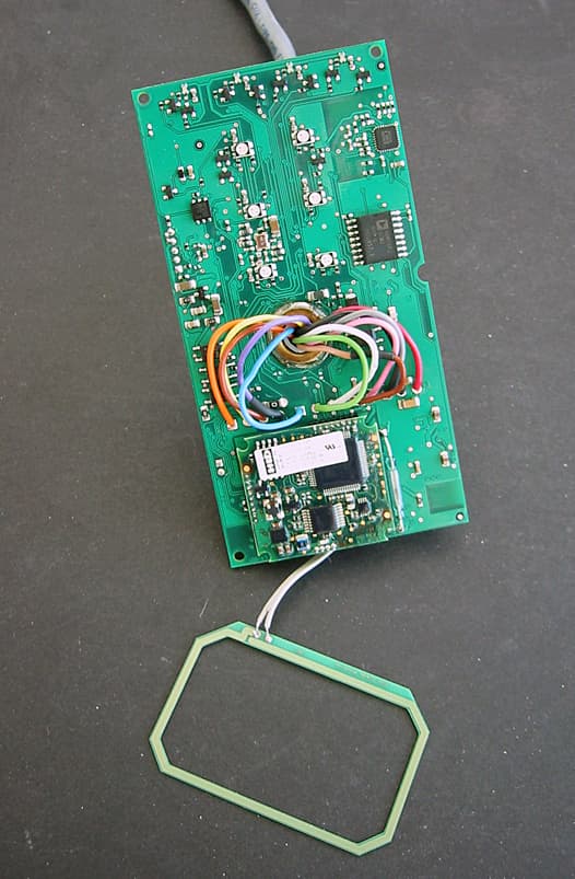
WIWAR402
Jan 23, 2012RFID Reader
Equipment Class
DXX - Part 15 Low Power Communication Device Transmitter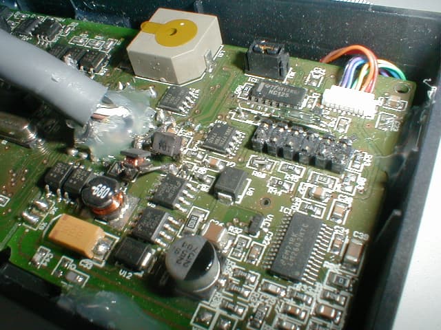
WIWTLR401
Dec 14, 2008Fingerprint keypad
Equipment Class
DXT - Part 15 Low Power Transceiver, Rx Verified