WJK-L-RFBT1wireless module transmitter
JULONG EDUCATIONAL TECHNOLOGY CO., LTD.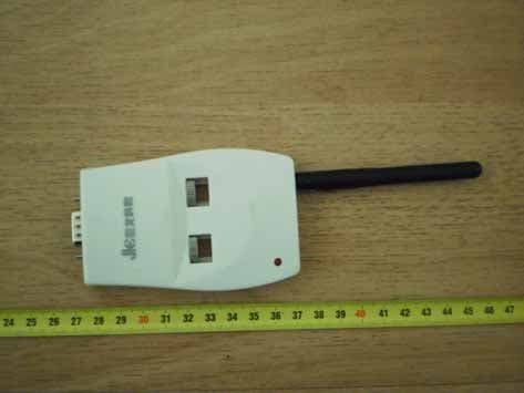
Click to zoom
Application Details
- Equipment Class
- DXX - Part 15 Low Power Communication Device Transmitter
- Date of Grant
- Sep 07, 2010
- Application Purpose
- Original Equipment
- Date of Application
- Sep 07, 2010
- Equipment Note
- wireless module transmitter
- Frequency Range
- 2402.00000000 - 2480.00000000
- Country
- China
Documents & Files
Document Text
Text extracted from the exhibit documents filed with the FCC. Open a document above to read the original.
Users Manual
USER__ GUIDE Page 2/10 1. Product Introduction This wireless module is a short-range data transmission and receiving equipment specially developed for the interactive whiteboard. Data can be inter-transmitted between the whiteboard and the PC upon connection. Connected to the PC, the wireless module enables users to operate the whiteboard or the computer freely as they are not limited by cables. Topological Diagram as shown below: Page 3/10 2. Product Features z Fully compliant with USB 2.0 standards. z Supports RS232 serial port. z Fully plug-and-play. z Full-duplex and bus-powered USB. z Launch with low power, LED indicator for transmission and reception. When the Wireless Transmitter and the Wireless Receiver are connected correctly, the LED indicator is red, or it will be flash one time a second. During transmission, the LED indicator is red and flash with long time until the transmission is end. z Smart data transfer, data transmission is fully automatic. All controls or transformation of signals shall be completed automatically. It can connect different type of whiteboard by set up the baud rate by the user. z High reliability, small size, light and portable. Page 4/10 Monolithic RFIC and single-chip MCU is used, thus there is less periphery circuit which ensures high performance reliability. The chips are overmolded by epoxy resins which are excellent electrical insulation materials. They protect integrated components from short circuiting, dust, humidity and other environmental factors that could damage the device. 3. Product Components This product is composed of the interactive whiteboard connector(Wireless Transmitter), PC connector(Wireless Receiver) and Power Adapter. The products said as shown below: Power Adapter Wireless Transmitter Wireless Receiver Page 5/10 4. Product Hardware Installation Step1USB PC connector: C onnect the Wireless Receiver to a USB port on the PC. As shown below: Step2Interactive whiteboard connector First, RS232 Connector(Wireless Transmitter) connect the interfaces on the whiteboard. Then connect the Power Adapter to the interfaces of DC Power on the whiteboard. As shown below: Page 6/10 5. The Installation of the Driver of the USB PC Connector. Please follow the instructions as shown below to install the Driver of the USB PC Connector underWindows XP. If the Wireless Module is used, the corresponding driver must be installed. Or else, the interactive whiteboard will can not exchange the data communication with the PC correctly. Page 7/10 Please insert the disc of the whiteboard. When it pop up the interface of installation guide, click,then click , and select ”Install Silicon Driver” ,then begin the installation of the USB Cable Driver. (1) Click “Next”, the confirmation prompt of Silicon USB driver installation appears: (2) Click “Next”, enter into installation license agreement: select “I accept the terms of the license agreement”, and then click ”Next”. Page 8/10 (2) Select folder where setup will install files. Click “Browse” to set the destination location. The default path is “c:\SiLabs\MCU_6”, and then click “Next”. Page 9/10 (4) Click “Install” to start the installation. (5) Select “Launch the CP210x VCP Driver Installer”, then click “Finish”. FCC S: TA TEM ENT: (6) Click “Install” to start the driver installation. (7) Complete installation. After installing correctly in “My Computer” “Properties” “Hardware” “Device Manager” “Port” can see the device “CP210X USB to UART Bridge Controller” After installation of USB-RS232 cable is completed, plug-in the USB cable, and to check the COM number of the CP210X USB to UART Bridge Controller in “My Computer”“Properties”“Hardware” “Device Manager” “Port” and to make sure that the COM number is less then 10 and the baud rate is 19200. 1. This device complies with Part 15 of the FCC Rules. Operation is subject to the following two conditions: (1) This device may not cause harmful interference. (2) This device must accept any interference received, including interference that may cause undesired operation. 2. Changes or modifications not expressly approved by the party responsible forcompliance could void the user's authority to operate the equipment. NOTE: This equipment has been tested and found to comply with the limits for aClass B digital device, pursuant to Part 15 of the FCC Rules. These limits are designed to provide reasonable protection against harmful interference in a residential installation. This equipment generates uses and can radiate radio frequency energy and,if not installed and used in accordance with the instructions, may cause harmful interference to radio communications. However, there is no guarantee that interference will not occur in a particular installation. If this equipment does cause harmful interference to radio or television reception, which can be determined by turning the equipment off and on, the user is encouraged to try to correct the interference by one or more of the following measures: Reorient or relocate the receiving antenna. Increase the separation between the equipment and receiver. Connect the equipment into an outlet on a circuit different from that towhich the receiver is connected. Consult the dealer or an experienced radio/TV technician for help.
Attestation Statements
Date:2010.08.31 To: Federal Communications Commission 7435 Oakland Mills Road Columbia, MD FCC ID: WJK- L-RFBT1 To Whom It May Concern: This letter is to ascertain that JULONG EDUCATIONAL TECHNOLOGY CO.,LTD. Product wireless module has been the units used for conducting FCC compliance testing, the DoC part will be tested by FCC recognized test lab. If you have any question or concerns, pls. contact us. Sincerely, Signature: Title or printed name: WeihongLu Title: Tech Manager Company Name: JULONG EDUCATIONAL TECHNOLOGY CO.,LTD. Company Name: JULONG EDUCATIONAL TECHNOLOGY CO.,LTD.
Cover Letter(s)
SCS-F18: Project and Product Certification Representative Authorization Letter Page 1 of 2 Rev 2.0 2206 Ringwood Avenue San Jose, CA 95131 Tel: 408-526-1188 Fax: 408-526-1088 Email: [email protected] Project and Product Certification Representative Authorization Letter Reason for Amendment (current / obsolete) Revision History Approved Date From To Initial Release (current) 1.0 1.0 Nov-14-2006 Revised wording (current) 1.0 2.0 Sept–25-2007 SCS-F18: Project and Product Certification Representative Authorization Letter Page 2 of 2 Rev 2.0 2010.08.31 To: SIEMIC, INC. 2206 Ringwood Avenue, San Jose, CA 95131 USA Dear Sir/Madam, Re: Project and Product Certification Representative Authorization Letter We, JULONG EDUCATIONAL TECHNOLOGY CO.,LTD. hereby authorize SIEMIC, INC. to act as a Certification Body for certifying for the following project(s): Product descriptionwireless module model nameL-RFBT1JL-RFBT4 We affirm that between SIEMIC and JULONG EDUCATIONAL TECHNOLOGY CO.,LTD., any difference in understanding, including test plan, measurement methods, applicable standards and relevant procedures and processes have been resolved prior to commencement of testing activities. Sincerely, Client’s signature Client’s name / titleWeihongLu/ Tech Manager Contact information / address JULONG EDUCATIONAL TECHNOLOGY CO.,LTD./ 4/F, Building T3,Keji Road South, Hi-Tech Industrial Park, NanShan District, Shenzhen
External Photos
Figure 1 General Appearance of the view Figure 2 General Appearance of the view
ID Label/Location Info
FCC ID: WJK-L-RFBT1 FCC ID Label Location
Internal Photos
Figure 1 inside of view Figure 2 Main Board Top Components View Figure 3 Main Board unshield View Figure 4 Main Board bottom Components View
Operational Description
Description The sample is supplied by the 4.8V power. The MCU with the crystal 22MHZ will constantly scan the various online sensor network of sensors voltage by I/O ports when the pen contact it ,and then enlarge it .It finally judge the exactly position through the algorithm that accurate coordinates. The wireless modules directly connected with the MCU to achieve the wireless function.
Schematics
1 2 3 4 ABCD 4 3 2 1 D C BA 1 62 73 8 495 10 J1DB9 7 9 131416171819 20 24252629 U1 JN513 9 R110 K R210 K C510 4 3.3 V 3.3 V C8100 UF/16 V C710 4 C610 4 +5V 3.3 V VD D 1 GND 2 CE 3 OU T 5 U3 KX 6219 C33 C20.1u F C40.1u F C30.1u F C10.1u F 3.3 V C1+ 1 V+ 2 C1- 3 C2+ 4 C2- 5 V- 6 T2OU T 7 R2IN 8 R2OU T 9 T2IN 10 T1IN 11 R1OU T 12 R1IN 13 T1OU T 14 GND 15 VCC 16 U2SP 323 2 3.3 V +5V R3 1K R4 1K C910 4 LE D1 R51K Wireless Transmission Wireless Transmission Red
Test Report
FCC PART 15.249 EMI MEASUREMENT AND TEST REPORT For JULONG EDUCATIONAL TECHNOLOGY CO.,LTD. 4/F, Building T3,Keji Road South, Hi-Tech Industrial Park, NanShan District, Shenzhen FCC ID: WJK-L-RFBT1 Aug.30, 2010 This Report Concerns: Original Report Equipment Type: wireless module transmitter Test Engineer: Eric Li Report No.: BATT201008301R-3 Receive EUT Date/Test Date: Aug.26, 2010 / Aug.26- Aug.30, 2010 Reviewed By: Jones song Prepared By: SHENZHEN BATT TESTING TECHNOLOGY CO.,LTD. Room B1104,Bldg.B,Xinbaoyuan, Xinanhu Commercial city, Bao’an District,Shenzhen,Guangdong,China Tel: 86-755-27754004 Fax: 86-755-27754182 Note: The test report is specially limited to the above company and this particular sample only. It may not be duplicated without prior written consent of SHENZHEN BATT TESTING TECHNOLOGY CO.,LTD. This report must not be used by the client to claim product certification,approval,or endorsement by NVLAP, NIST or any agency of the US Government. JULONG EDUCATIONAL TECHNOLOGY CO.,LTD. FCC ID: WJK-L-RFBT1 BST FCC ID REPORT : BATT201008301R-3 Page 2/21 TABLE OF CONTENTS 1. GENERAL INFORMATION .................................................................................................... 3 1.1. Report information ............................................................................................................ 3 1.2. Measurement Uncertainty ................................................................................................. 3 2. PRODUCT DESCRIPTION ...................................................................................................... 4 2.1. EUT Description ............................................................................................................... 4 2.2. Block Diagram of EUT Configuration .............................................................................. 4 2.3. Support Equipment List .................................................................................................... 4 2.4. Test Conditions ................................................................................................................. 5 3. FCC ID LABEL ........................................................................................................................... 6 4. TEST RESULTS SUMMARY ................................................................................................... 7 Modifications ................................................................................................................................ 7 5. TEST EQUIPMENT USED ....................................................................................................... 8 6. CONDUCTED POWER LINE TEST ....................................................................................... 9 6.1. Test Equipment ................................................................................................................. 9 6.2. Test Procedure ................................................................................................................... 9 6.3. Test Setup .......................................................................................................................... 9 6.4. Configurating of the EUT ................................................................................................. 9 6.5. EUT Operating Condition ............................................................................................... 11 6.6. Conducted Power line Emission Limits .......................................................................... 11 6.7. Conducted Power Line Test Result ................................................................................. 11 7. RADIATED EMISSION TEST ............................................................................................... 15 7.1. Test Equipment ............................................................................................................... 15 7.2. Test Procedure ................................................................................................................. 15 7.3. Radiated Test Setup ........................................................................................................ 15 7.4. Confihuration of the EUT ............................................................................................... 15 7.5. EUT Operating Condition ............................................................................................... 15 7.6. Radiated Emission Limit ................................................................................................. 16 7.7. Radiated Emission Test Result ....................................................................................... 17 8. BAND EDGE ............................................................................................................................. 19 8.1. Test Equipment ............................................................................................................... 19 8.2. Test Procedure ................................................................................................................. 19 8.3. Configuration of The EUT .............................................................................................. 19 8.4. EUT Operating Condition ............................................................................................... 19 8.5. Band Edge FCC 15.249(d) Limit .................................................................................... 19 8.6. Band Edge Test Result .................................................................................................... 19 JULONG EDUCATIONAL TECHNOLOGY CO.,LTD. FCC ID: WJK-L-RFBT1 BST FCC ID REPORT : BATT201008301R-3 Page 3/21 1. GENERAL INFORMATION 1.1. Report information 1.1.1.This report is not a certificate of quality; it only applies to the sample of the specific product/equipment given at the time of its testing. The results are n…
Text truncated - open the document above for the full version.
Test Setup Photos
TEST SUTUP PHOTO
Contact Information
Applicant
WEIHONG LU(TECH MANAGER)
Test Firm
EMTEK (Shenzhen) Co., Ltd.David Lee
Technical Specifications
| # | Rule Parts | Frequency Range | Power Output |
|---|---|---|---|
| 1 | 15C | 2.40 GHz - 2.48 GHz | - |
Other Applications from JULONG EDUCATIONAL TECHNOLOGY CO., LTD.
WJK-TB3124RDV
Jun 06, 2010WIRELESS TABLET
Equipment Class
DXX - Part 15 Low Power Communication Device Transmitter
WJKJL-V2
Feb 02, 2010VOTE
Equipment Class
DXX - Part 15 Low Power Communication Device Transmitter