WM5UD-3000TVPART15 SPREAD SPECTRUM TRANSMITTER (AUDIO DONGLE)
UNEEDS Commerce Co.,Ltd.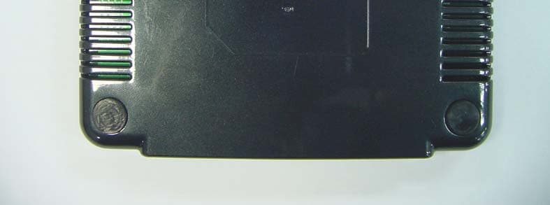
Click to zoom
Application Details
- Equipment Class
- DSS - Part 15 Spread Spectrum Transmitter
- Date of Grant
- Mar 03, 2010
- Application Purpose
- Original Equipment
- Date of Application
- Feb 28, 2010
- Equipment Note
- PART15 SPREAD SPECTRUM TRANSMITTER (AUDIO DONGLE)
- Frequency Range
- 2402.00000000 - 2480.00000000
- Company
- UNEEDS Commerce Co.,Ltd.
- Country
- South Korea
Documents & Files
Document Text
Text extracted from the exhibit documents filed with the FCC. Open a document above to read the original.
Users Manual
UD-3000TV User Guide CONTENTS 1 What is Bluetooth? 2 Introduce of UD-3000TV 3 Controller and Connector 4 Getting Started 5 Auto Connection 6 Frequently Asked Questions and Troubleshooting 7 CAUTION 8 Product Specification 9 Customer Service 10 Label Information Note : For intentional radiator shall caution the user that changes or modifications not expressly approved by the party responsible for compliance could void the user’s authority to operate the equipment Caution: The use of a permanently attached antenna or of an antenna that user a unique coupling to the intentional radiator shall be considered sufficient to comply with the provisions of required this section. The manufacturer may design the unit so that broken antenna can be replaced by the user, but the use of a standard antenna jack or electrical connector is prohibited. This instruction manual is contained to required statement from FCC & R&TTE Hereby, UNEEDS Commerce Co.,Ltd. Declares that this Wireless Headset and Base is in compliance with the essential requirements and other relevant provisions of Directive 1999/5/EC 1. What is Bluetooth? Bluetooth is a standardized, short range wireless solution. In much the same way WAN and LAN technologies created wide and local area networks of connected devices, Bluetooth allows you to create a PAN, Personal Area Network, of devices within a tight, 30ft or less, range. It is perfect for input devices like mice and keyboards, tethering cell phones to use as modems and for audio devices like this headset. 2. Introduce of UD-3000TV UD-3000TV is transceiver which can transmit the bluetooth signal to two headsets through Digital TV or Digital Media Devices such as PDA, PMP, Laptop, Audio, etc. This is designed for using both SPDIF cable and 3.5 pi analogue cable. (Can not be used simultaneously) 3. Controls and Connector ① Pairing Button 1 ② Pairing Button 2 ③ 3.5 pi/SPDIF cable input socket ④ USB charging port ⑤ Power port ⑥ Power signal lamp 4. Getting Started (1) Connecting to the TV or Digital Media Devices ① Insert the 3.5 pi cable or SPDIF cable on the output socket of TV or Digital Media Devices ※ refer to the manual of TV or Digital Media Devices. ② Insert the 3.5 pi cable or SPDIF cable on the input socket of UD-3000TV. ③ Connect the adapter on the Power port of UD-3000TV. ※ If you want to switch the cable while you are using the UD-3000TV, you should remove the adapter. This is an important phase for UD-3000TV to decide which sound signal it processes. (2) Pairing the Headset ① To enter the pairing mode of Bluetooth headset which you would like to connect. ② Press the Pairing Button 1 of UD-3000TV. Pairing Button 1’s lamp will be rapidly flashing blue light. ③ Rapidly flashing blue light indicates that you are in pairing mode. ④ The blue lamp of Pairing Button 1 is completely will be on, once pairing is complete. ⑤ To connect the second headset just follow the above steps but, use Pairing Button 2. ※ Warning The first time you use the headset, you will need to pair it with the device you intend to use the headset with. Pairing creates a link between the headset and the connected device. Once done, you should not have to repair with the same device again. It also works for exterminating the interruption and sets up the security. After that, UD-3000TV is in perfect working order. But if you paired your headset to other devices but UD-3000TV, you should pair it again. 5. Auto Connection Once done the first pairing, you should not have to repair with the same device again. But the headset should not be paired with other devices. And the power of headset and UD-3000TV should be ON. (1) If the Power of Headset is OFF ① You should turn on the headset. (Refer the manual of your headset to turn it on) ② Pairing will be automatically done after a while. ③ In this case you should not have to press the pairing button. ※ if you press the pairing button, you should pairing it again. (2) If the Power of UD-3000TV is OFF ① To Power On the UD-3000TV, connecting the adapter to the power port of UD-3000TV ② Pairing will be automatically done after a while. ※ if you press the pairing button, you should pairing it again. 6. Frequently Asked Questions and Troubleshooting ⊙ Unavailable to hear any audio through the headset. - Check to make sure that the headset is powered on. - Make sure that the devices are properly paired and connected to each other. ⊙ The devices can not be automatically paired. - Make sure the power of headset and UD-3000TV is ON. - Check whether or not the headset is paired with other devices. If it is, disconnect the headset with other devices. ⊙ Getting a noise or lip-sync. - Make sure that the battery of headset is enough. If not please recharge it. - If the battery is fully charged, please pairing it again. ⊙ What is the maximum range between the headset and the UD-3000TV? - Typically up to 10 meters with clear line of sight. However, this distance may be reduced if there are sources of interference or other radios such as Wifi being used in the same area. ⊙ When it is disconnected by furthering from Dongle while you are using. - Turn the Power-off and Power-on again, then it will be automatically connected. If you have any inquiry please visit our web site --Æ www.u-needs.co.kr 7. CAUTIONS 1) Keep the headset away from flames. 2) Do not drop the headset or expose it to shock as it may reduce the expected life of the device. 3) Do not modify, disassemble or repair this product by yourself. 4) Do not expose this device to water or excessive moisture. 5) Do not clean with chemical cleaning products. 6) Only use the provided charging cable for charging. 7) Store at room temperature when not in use. 8) This device is compliant to Bluetooth 2.0 specifications and may not be compatible with other Bluetooth devices. 9) Do not use the headset at high volumes for a prolonged period to prevent damage to your hearing. ※ Exemptions 1) The manufacturer, resellers and agents are not respo…
Text truncated - open the document above for the full version.
Cover Letter(s)
Head office & Test Lab: 180-254, Annyeong-dong, Hwaseong-si, Gyeonggi-do, South korea 445-380 Tel: +82-31-222-4251 / Fax: +82-31-222-4252 www.kosteclab.com [email protected] TIMCO ENGINEERING INC. TCB & FCB 849 NW State Road 45 FCC Approvals Newberry, Florida 32669 Industry Canada Approvals http://www.timcoengr.com Notified Body for Europe 888.472.2424 F 352.472.2030 email: [email protected] SUBJECT: UPLOAD FILES TO WEBSITE Applicant: UNEEDS Commerce Co.,Ltd.. Product: AUDIO DONGLE Model: UD-3000TV FCC ID: WM5UD-3000TV Dear Sir/Madam As appointed agent for UNEEDS Commerce Co.,Ltd., we submit the application to Timco Engineering Inc, for certification of the above product. Please review all files uploaded to TEI electronic filing site. ※ Note: RF part of this product is consist of two(2) Bluetooth chip type on PCB board I you have any queries, please do not hesitate to contact us Yours truly, KOSTEC Co.,Ltd. Seok Jin, Jeong / Assistance Manager e-mail: [email protected]
Cover Letter(s)
UNEEDS Commerce Co.,Ltd. Digital Empire II, 486, Shin Dong, Yongtong Gu, Suwon, Gyeonggi Do, Korea Tel No.:82-31-695-7760 Fax No.:82-31-695-7764 Federal Communications Commission Authorization and Evaluation Division 1435 Oakland Mills Road Columbia, MD 21046 SUBJECT: DoC for Receiver portion of AUDIO DONGLE To Whom It May Concern: We, the undersigned, hereby attest to the fact that we has been apply the Declaration of Conformity procedure to the class B, about receiving portion of AUDIO DONGLE (FCC ID: WM5UD-3000TV) of this composite filing. Best Regards, Chun IL Yun / Assistance manager
Cover Letter(s)
UNEEDS Commerce Co.,Ltd. Digital Empire II, 486, Shin Dong, Yongtong Gu, Suwon, Gyeonggi Do, Korea Tel No.:82-31-695-7760 Fax No.:82-31-695-7764 KOSTEC Co.,Ltd. 180-254 Annyeong-dong Hwaseong-si, Gyeonggi-do South korea 445-380 To Whom It May Concern: Please be advised that UNEEDS Commerce Co.,Ltd. Authorizes KOSTEC Co., Ltd. To act on our behalf, until otherwise notified, for applications submitted to Timco Engineering, Inc. We certify that we are not subject to denial of federal benefits, that includes FCC benefits, pursuant to Section 5301 of the Anti-Drug Abuse ACT of 1988, U.S.C. 862. Futher, no party, as defined in 47 CFR 1.2002(B), to the application is subject to denial of federal benefits, that includes FCC benefits. Thank you for your attention to this matter. Chun IL Yun / Assistance manager
Cover Letter(s)
UNEEDS Commerce Co.,Ltd. Digital Empire II, 486, Shin Dong, Yongtong Gu, Suwon, Gyeonggi Do, Korea Tel No.:82-31-695-7760 Fax No.:82-31-695-7764 Federal Communications Commission Authorization and Evaluation Division Confidentiality Request regarding application for certification of FCC ID: WM5UD-3000TV Pursuant to Sections 0.457 and 0.459 of the Commission’s Rules, we hereby request confidential treatment of information accompanying this application as outlined below: Exhibit Type File Name Block diagram Schematic diagram PCB Layout Part List Operational Description Block diagram_UD-3000TV. pdf Schematic diagram_UD-3000TV. pdf Material Layout_UD-3000TV. pdf BOM List_UD-3000TV. pdf Operational description_UD-3000TV. pdf The above materials contain trade secrets and proprietary information not customarily released to the public. The public disclosure of these materials may be harmful to the applicant and provide unjustified benefits to its competitors. The applicant understands that pursuant to Section 0.457 and 0.459 of the Rules, disclosure of this application and all accompanying documentation will not be made before the date of the Grant for this application. Sincerely, Chun IL Yun / Assistance manager
External Photos
Head office & Test Lab: 180-254, Annyeong-dong, Hwaseong-si, Gyeonggi-do, South korea 445-380 Tel: +82-31-222-4251 / Fax: +82-31-222-4252 www.kosteclab.com [email protected] Report No: KST-FCR-100001 Page: 1 / 4 KST-FCR-RFS-Rev.0.2 This report shall not be reproduced except in full without the written approval of KOSTEC Co., Ltd. Appendix 2. External photographs Front Rear Head office & Test Lab: 180-254, Annyeong-dong, Hwaseong-si, Gyeonggi-do, South korea 445-380 Tel: +82-31-222-4251 / Fax: +82-31-222-4252 www.kosteclab.com [email protected] Report No: KST-FCR-100001 Page: 2 / 4 KST-FCR-RFS-Rev.0.2 This report shall not be reproduced except in full without the written approval of KOSTEC Co., Ltd. Appendix 2. External photographs Upper Bottom Head office & Test Lab: 180-254, Annyeong-dong, Hwaseong-si, Gyeonggi-do, South korea 445-380 Tel: +82-31-222-4251 / Fax: +82-31-222-4252 www.kosteclab.com [email protected] Report No: KST-FCR-100001 Page: 3 / 4 KST-FCR-RFS-Rev.0.2 This report shall not be reproduced except in full without the written approval of KOSTEC Co., Ltd. Appendix 2. External photographs Left Right Head office & Test Lab: 180-254, Annyeong-dong, Hwaseong-si, Gyeonggi-do, South korea 445-380 Tel: +82-31-222-4251 / Fax: +82-31-222-4252 www.kosteclab.com [email protected] Report No: KST-FCR-100001 Page: 4 / 4 KST-FCR-RFS-Rev.0.2 This report shall not be reproduced except in full without the written approval of KOSTEC Co., Ltd. Appendix 2. External photographs Adaptor (Full) Adaptor (Label part)
ID Label/Location Info
Head office & Test Lab: 180-254, Annyeong-dong, Hwaseong-si, Gyeonggi-do, South korea 445-380 Tel: +82-31-222-4251 / Fax: +82-31-222-4252 www.kosteclab.com [email protected] Report No: KST-FCR-100001 Page: 1 / 1 KST-IRF-FCR-Rev.0.2 This report shall not be reproduced except in full without the written approval of KOSTEC Co., Ltd. Appendix4. Sample Label & Location Label Information The following is a sample copy of the label that will be placed on the inside cabinet of the product. The FCC ID and CE Loge is marked in the product label with model No. The product label is made of plastic material and all information is indelibly printed on the label. Statement required from authorization Authority is describe the user manual UNEEDS Co.,Ltd. Product: AUDIO DONGLE Model No : UD-3000TV Rating : 6 V 500 mA FCC ID : WM5UD-3000TV 인증번호 : UNE-UD-3000TV This device complies with Part 15 of the FCC Rules. Operation is subject to the following two conditions: (1) this device may not cause harmful Interference, and (2) this device must accept any interference received , this Including interference that may cause undesired operation. This device is a 2.4 GHz wireless digital transceiver, intended for indoor home and office use in all EU member states, Label location The label shown above shall be permanently affixed at a conspicuous location on the device and be readily visible to the user at the time purchase. The label is affixed with permanent adhesive to the enclosure and can not be readily detachable. The label is located here. 35 mm 30 mm
Operational Description
Specifications for Approval 결 재 Person in Charge Q.A R&D Approved by S.J.Y J.B.H L.S.H N.J.S 02/19 02/19 02/19 02/19 BUYER U-NEEDS MODEL UD-3000TV Part Name BLUETOOTH CHIP ANTENNA Part Code - Arro Code ABM6020B2 205-11, Anyang 7-Dong, Manan-Gu, Anyang-Si, Gyeonggi-Do, Korea TEL : (031)441-4181, FAX : (031)448-4194 Antenna Specifications DATE 2010. 02. 19 REV. 1.0 MODEL UD-3000TV TYPE BLUETOOTH CHIP PAGE 2/19 - Table of Contents - 1. Approval History 2. Technical Properties 2.1 General Properties 2.2 Electrical Properties 2.3 Mechanical Properties 3. Electrical Requirements 3.1 VSWR & Smith chart 3.2 PASSIVE 3.3 JIG DATA 3.4 IMPEDANCE 3.5 Antenna Gain 3.6 JIG Measurement 4. Mechanical Specifications 4.1 Mechanical Drawing 4.2 Figure of assembled Antenna 5. Soldering Conditions 6. NOTICE 7. Packing Condition 8.1 Carrier Tape Properties 8.2 Reel Packing Properties 8.3 Box Packing Properties 8. ROHS Report Antenna Specifications DATE 2010. 02. 19 REV. 1.0 MODEL UD-3000TV TYPE BLUETOOTH CHIP PAGE 3/19 1. Approval History NO DATE Before a change After a change Reason REV 1 2 3 4 5 6 7 8 9 10 11 12 13 14 15 16 17 Antenna Specifications DATE 2010. 02. 19 REV. 1.0 MODEL UD-3000TV TYPE BLUETOOTH CHIP PAGE 4/19 2. Technical Properties 2.1 General Properties MODEL ANTENNA ANTENNA TYPE CHIP ANTENNA APPLICATIONS BLUETOOTH ANTENNA 2.2 Electrical Properties SEPARATION MAIN DIVERSITY FREQUENCY RANGE 2,40 ~ 2,485(㎒) 2,40 ~ 2,485(㎒) V.S.W.R LESS TNEN 2.3:1 LESS TNEN 3.5:1 .GAIN(dBi) (3D MEASUREMENT) (3D MEASUREMENT) IMPEDANCE(NOMINAL) 50(Ω) POLARIZATION LINEAR RADIATION PATTERN OMNIDIRECTIONAL 2.3 Mechanical Properties CONNECTOR N/A LENGTH REF DRAWING (No. 4.1) TEMPERATURE -20 ~ 70(°C) WEIGHT 0.1(g) Antenna Specifications DATE 2010. 02. 19 REV. 1.0 MODEL UD-3000TV TYPE BLUETOOTH CHIP PAGE 5/19 3. Electrical requirements 3.1 VSWR & Smith chart VSWR & smith chart (MAIN) Antenna Specifications DATE 2010. 02. 19 REV. 1.0 MODEL UD-3000TV TYPE BLUETOOTH CHIP PAGE 6/19 VSWR & smith chart (DIVERSITY) Antenna Specifications DATE 2010. 02. 19 REV. 1.0 MODEL UD-3000TV TYPE BLUETOOTH CHIP PAGE 7/19 3.2 PASSIVE PASSIVE (3D MEASUREMENT) - MAIN Antenna Specifications DATE 2010. 02. 19 REV. 1.0 MODEL UD-3000TV TYPE BLUETOOTH CHIP PAGE 8/19 PASSIVE (3D MEASUREMENT) - MAIN Antenna Specifications DATE 2010. 02. 19 REV. 1.0 MODEL UD-3000TV TYPE BLUETOOTH CHIP PAGE 9/19 3.3 JIG DATA Measurement Equipment NETWORK ANALYZER E8357A Measurement Cable TYPE N-MALE TO N-FEMAIL LENGTH 55㎝ PCB Copper plate SIZE 40(Horizontal)x40(Vertical)x1(t) JIG State frequency BLUE TOOTH Standard Resonant frequency 2.25GHz (±50MHz) Antenna Specifications DATE 2010. 02. 19 REV. 1.0 MODEL UD-3000TV TYPE BLUETOOTH CHIP PAGE 10/19 3.4 IMPEDANCE Measurement Methodology: Setting equipments as shown in fig. 3-1, connecting the hand set to the reflection port of the Network Analyzer, measure the impedance. (Fig. 3-1) Antenna Specifications DATE 2010. 02. 19 REV. 1.0 MODEL UD-3000TV TYPE BLUETOOTH CHIP PAGE 11/19 3.5 Gain Measurement Method : As shown in fig.3-2, setting the horn antenna as standard antenna, measure the gain by [dBi]. (Fig.3-2) Antenna Specifications DATE 2010. 02. 19 REV. 1.0 MODEL UD-3000TV TYPE BLUETOOTH CHIP PAGE 12/19 3.6 Jig Measurement Measurement Method : Setting equipments as shown in fig. 3-5, connecting the measurement jig to the reflection port of the Network Analyzer, measure VSWR of the reference antenna and specimens. (Fig.3-3) Antenna Specifications DATE 2010. 02. 19 REV. 1.0 MODEL UD-3000TV TYPE BLUETOOTH CHIP PAGE 13/19 4. Mechanical Specifications 4.1 Mechanical Drawing 4.2 Figure of assembled antenna Antenna Specifications DATE 2010. 02. 19 REV. 1.0 MODEL UD-3000TV TYPE BLUETOOTH CHIP PAGE 14/19 5. Soldering Conditions (Pb Free) 1) To prevent deterioration of antenna performance, fellow conditions are satisfied. - Only reflow soldering process is available. - Inactive flux should be used.(Contents of Cl is below 0.2%) - Reflow cycle must be under 3 times. Solder paste : Ag/Sn/Cu:96.5/3.0/0.5 (Fig.6-1) 6. Notice 1) Specimens should be kept in environment of -5 ~ 40°C and under RH70% for standby.(MSL Level 1) 2) Working in high temperature or humidity, or environment of exposure to chlorine gas or sulfur can cause the dielectric chip antenna to deteriorate in ability of soldering on electrode. 3) Mechanical Impact should be avoided to prevent crack by the weight of Dielectric Chip Antenna itself. 4) Dielectric Chip Antenna should be soldered within 6months. The chip antenna over 6months should be checked about soldering availability Antenna Specifications DATE 2010. 02. 19 REV. 1.0 MODEL UD-3000TV TYPE BLUETOOTH CHIP PAGE 15/19 7. Packing Specifications 7.1 Carrier tape specifications 1) Dimensions (Fig.8-1) ANTENNA SIZE(㎜) A B C D 6x2x1.5t 4.0±0.1 2.1 ~ 2.2 6.1 ~ 6.2 1.65±0.1 2) Material and surface resistance - Carrier tape : 10 9 ~ 10 11 Ω - Cover tape : 10 8 ~ 10 11 Ω - Reel : 10 9 ~ 10 11 Ω Antenna Specifications DATE 2010. 02. 19 REV. 1.0 MODEL UD-3000TV TYPE BLUETOOTH CHIP PAGE 16/19 7.2 Reel Specifications 1) Size (Fig.8-2) Item DIA WIDTH CORE DIA HOLE Dimention(㎜) 180.0 ~ 183.0 17.0±0.3 60.0±1 13.0±0.5 2) Labeling and Winding Method (Fig. 8-3) 3) Material - Plastic reel : GPPS (General Purpose Poly Styrene) resin. WIDTH DIA HOLECORE DIA Antenna Specifications DATE 2010. 02. 19 REV. 1.0 MODEL UD-3000TV TYPE BLUETOOTH CHIP PAGE 17/19 7.3 Box Specifications 1) Contents of labels - As shown in Fig.8-4, ① RoHS Mark should be on the box. ※ It need to confirm the product and quantity before sign on the Product Details table. (Fig. 8-4) 2) Labeling Method - Label should be attached as shown in Fig.8-5 - If the product is for CKD, CKD label should be attached on the right top side of box front and opposite face of it. (Fig. 8-5) RoHS Antenna Specifications DATE 2010. 02. 19 REV. 1.0 MODEL UD-3000TV TYPE BLUETOOTH CHIP PAGE 18/19 8. RoHS Report 1) PREPREG / POWDER Antenna Specifications DATE 2010. 02. 19 REV. 1.0 MODEL UD-300…
Text truncated - open the document above for the full version.
RF Exposure Info
Head office & Test Lab: 180-254, Annyeong-dong, Hwaseong-si, Gyeonggi-do, South korea 445-380 Tel: +82-31-222-4251 / Fax: +82-31-222-4252 www.kosteclab.com [email protected] Applicant Company Name: UNEEDS Commerce Co.,Ltd. RF Exposure information Federal Communication Commission Equipment Authorization Division, Application Processing Branch 7435 Oakland Mills Road Columbia, MD 21048 Feb 10, 2010 Attention: Reviewing Engineer RE: RF exposure information for the equipment (AUDIO DONGLE/FCC ID: WM5UD-3000TV) The device is Base Type and it is not be co-located or operating in conjunction with any other antenna or transmitter and also use of a permanently attached antenna that user a unique coupling to the intentional radiator comply with the FCC Rule according to this product’s antenna type is a Chip and it’s gain is 1.10dBi the table below is excepted from Table 1B of 47 CFR 1.1310 titled Limits for Maximum Permissible Exposure (MPE), Limits for General Population /Uncontrolled Exposure Frequency Range (MHz) Powr Density (mW/cm 2 ) Averaging Time (minutes) 300 – 1 500 f/1500 30 1 500 – 10 000 1.0 30 The equipment is in the following frequency ranges So that the applicable limits are: Frequency range Limit 2 402 – 2 480 MHz 1 mW/cm 2 The equipment is a Bluetooth class 1, and it’s duty cycle = 1 Under conditions stated above MPE limits can be guaranteed as the calculation below shows: Maximum conducted output power: 4.14 mW (0.00414 W) measured by test Engineer *Please see the page 18/42 of Test report Duty cycle: 1 Equivalente conducted output power = Maxmum conducted output power x Duty cycle = 4.14 mW X 1 = 4.14 mW Maximum antenna gain = 1.10 dBi (1.288: Numerical gain) Under conditions stated above MPE limits can be guaranteed as the calculation below shows MPE calculation formula is as a below ; P.G/4.pi.R 2 = 4.14 m W•1.288/4•pi•(20cm 2 ) = 0.00106 mW/cm 2 ∴ So, above calculated 0.00108 mW/cm 2 is less than 1.0 (mW/cm 2 ) Head office & Test Lab: 180-254, Annyeong-dong, Hwaseong-si, Gyeonggi-do, South korea 445-380 Tel: +82-31-222-4251 / Fax: +82-31-222-4252 www.kosteclab.com [email protected] Applicant Company Name: UNEEDS Commerce Co.,Ltd. Where, S = power density in Mw/cm 2 P = power input to the antenna in mW G = power gain of the antenna in the direction of interest relative to an isotropic radiato R = distance to the centre of radiation of the antenna in cm (20 cm prediction distance)
Test Report
Head office & Test Lab: 180-254, Annyeong-dong, Hwaseong-si, Gyeonggi-do, South korea 445-380 Tel: +82-31-222-4251 / Fax: +82-31-222-4252 www.kosteclab.com [email protected] Report No: KST-FCR-100001 Page: 1 / 42 KST-FCR-RFS-Rev.0.2 This report shall not be reproduced except in full without the written approval of KOSTEC Co., Ltd. TEST REPORT Report No: KST-FCR-100001 Applicant Name UNEEDS Commerce Co.,Ltd. Address Digital EmpireII, 486, Shin Dong, Yongtong Gu, Suwon, Gyeonggi Do, South Korea Manufacturer Name UNEEDS Commerce Co.,Ltd. Address Digital EmpireII, 486, Shin Dong, Yongtong Gu, Suwon, Gyeonggi Do, South Korea Equipment Name AUDIO DONGLE Model No UD-3000TV Brand Name None FCC ID WM5UD-3000TV Test Standard FCC CFR 47, Part 15. Subpart C-15.247 Test Date(s) 2010. 02. 08 ~ 2009. 02. 10 Issue Date 2008. 02. 11 Test Result Compliance Supplementary Information The device bearing the brand name and FCC ID specified above has been shown to comply with the applicable technical standards as indicated in the measurement report and was tested in accordance with measurement procedures specified in ANSI C 63.4-2003. We attest to the accuracy of data and all measurements reported herein were performed by KOSTEC Co., Ltd. and were made under Chief Engineer’s supervision. We assume full responsibility for the completeness of these measurements and vouch for the qualifications of all persons taking them. Tested by Mi Young, Lee Approved by Gyeong Hyeon, Park Signature Signature Head office & Test Lab: 180-254, Annyeong-dong, Hwaseong-si, Gyeonggi-do, South korea 445-380 Tel: +82-31-222-4251 / Fax: +82-31-222-4252 www.kosteclab.com [email protected] Report No: KST-FCR-100001 Page: 2 / 42 KST-FCR-RFS-Rev.0.2 This report shall not be reproduced except in full without the written approval of KOSTEC Co., Ltd. Table of Contents 1. GENERAL INFORMATION .............................................................................................................. 3 1.1 Test Facility ............................................................................................................................................... 3 1.2 Location .................................................................................................................................................... 3 2. EQUIPMENT DESCRIPTION ........................................................................................................... 4 3. SYSTEM CONFIGURATION FOR TEST ......................................................................................... 5 3.1 Characteristics of equipment.................................................................................................................... 5 3.2 Configuration of EUT ................................................................................................................................ 5 3.3 Product Modification ................................................................................................................................. 5 3.4 Operating Mode........................................................................................................................................ 5 3.5 Test Configuration..................................................................................................................................... 5 3.6 Table for Test condition............................................................................................................................. 6 3.7 Test Jig ..................................................................................................................................................... 6 3.8 Used Test Equipment List......................................................................................................................... 7 4. SUMMARY TEST RESULTS ............................................................................................................ 8 5. MEASUREMENT RESULTS ............................................................................................................ 9 5.1 Carrier Frequency Separation .................................................................................................................. 9 5.2 Number of hopping frequencies ............................................................................................................. 13 5.3 Time of occupancy ( Dwell Time) ........................................................................................................... 15 5.4 Max. Conducted peak output power ...................................................................................................... 17 5.5 Band edge Compliance of RF emission ................................................................................................. 21 5.6 Spurious RF conducted emissions ......................................................................................................... 24 5.7 Spurious RF Radiated emissions ........................................................................................................... 30 5.8 AC Power Conducted emissions ............................................................................................................ 39 5.9 Antenna requirement .............................................................................................................................. 42 Head office & Test Lab: 180-254, Annyeong-dong, Hwaseong-si, Gyeonggi-do, South korea 445-380 Tel: +82-31-222-4251 / Fax: +82-31-222-4252 www.kosteclab.com [email protected] Report No: KST-FCR-100001 Page: 3 / 42 KST-FCR-RFS-Rev.0.2 This report shall not be reproduced except in full without the written approval of KOSTEC Co., Ltd. 1. GENERAL INFORMATION 1.1 Test Facility Test laboratory and address KOSTEC Co., Ltd. 180-254, Annyeong-dong, Hwaseong-si, Gyeonggi-do, South Korea The open area field test site and conducted measurement facility are used for these testing. This sit…
Text truncated - open the document above for the full version.
Test Setup Photos
Head office & Test Lab: 180-254, Annyeong-dong, Hwaseong-si, Gyeonggi-do, South korea 445-380 Tel: +82-31-222-4251 / Fax: +82-31-222-4252 www.kosteclab.com [email protected] Report No: KST-FCR-100001 Page: 1 / 4 KST-IRF-FCR-Rev.0.2 This report shall not be reproduced except in full without the written approval of KOSTEC Co., Ltd. Appendix1. Photographs of test setup(Conducted RF measurement) TEST JIG EUT with the TEST JIG Head office & Test Lab: 180-254, Annyeong-dong, Hwaseong-si, Gyeonggi-do, South korea 445-380 Tel: +82-31-222-4251 / Fax: +82-31-222-4252 www.kosteclab.com [email protected] Report No: KST-FCR-100001 Page: 2 / 4 KST-IRF-FCR-Rev.0.2 This report shall not be reproduced except in full without the written approval of KOSTEC Co., Ltd. EUT with the TEST JIG and Controlled S/W Blank Head office & Test Lab: 180-254, Annyeong-dong, Hwaseong-si, Gyeonggi-do, South korea 445-380 Tel: +82-31-222-4251 / Fax: +82-31-222-4252 www.kosteclab.com [email protected] Report No: KST-FCR-100001 Page: 3 / 4 KST-IRF-FCR-Rev.0.2 This report shall not be reproduced except in full without the written approval of KOSTEC Co., Ltd. Appendix1. Photographs of test setup Power line conducted emission_ Front Power line conducted emission_ Rear Head office & Test Lab: 180-254, Annyeong-dong, Hwaseong-si, Gyeonggi-do, South korea 445-380 Tel: +82-31-222-4251 / Fax: +82-31-222-4252 www.kosteclab.com [email protected] Report No: KST-FCR-100001 Page: 4 / 4 KST-IRF-FCR-Rev.0.2 This report shall not be reproduced except in full without the written approval of KOSTEC Co., Ltd. Appendix1. Photographs of test setup (Radiated RF measurement) (Below 1 ㎓) (Above 1 ㎓)
Contact Information
Applicant
Chun IL Yun(Assistance Management)
Test Firm
KOSTEC Co., LtdLee Chang-Ho
Technical Specifications
| # | Rule Parts | Frequency Range | Power Output |
|---|---|---|---|
| 1 | 15C | 2.40 GHz - 2.48 GHz | 5.00 mW |
Other Applications from UNEEDS Commerce Co.,Ltd.
WM5UM-1100
Aug 15, 2011FHSS SPREAD SPECTRUM DEVICE (BLUETOOTH STEREO HEADSET)
Equipment Class
DSS - Part 15 Spread Spectrum Transmitter
WM5UNB-2000
Aug 14, 2011FHSS SPREAD SPECTRUM DEVICE (BLUETOOTH STEREO HEADSET)
Equipment Class
DSS - Part 15 Spread Spectrum Transmitter
WM5UM-1000
Sep 16, 2010PART15 SPREAD SPECTRUM TRANSMITTER (BLUETOOTH MONO HEADSET)
Equipment Class
DSS - Part 15 Spread Spectrum Transmitter