WM5UM-1000PART15 SPREAD SPECTRUM TRANSMITTER (BLUETOOTH MONO HEADSET)
UNEEDS Commerce Co.,Ltd.
Click to zoom
Application Details
- Equipment Class
- DSS - Part 15 Spread Spectrum Transmitter
- Date of Grant
- Sep 16, 2010
- Application Purpose
- Original Equipment
- Date of Application
- Sep 15, 2010
- Equipment Note
- PART15 SPREAD SPECTRUM TRANSMITTER (BLUETOOTH MONO HEADSET)
- Frequency Range
- 2402.00000000 - 2480.00000000
- Company
- UNEEDS Commerce Co.,Ltd.
- Country
- South Korea
Documents & Files
Document Text
Text extracted from the exhibit documents filed with the FCC. Open a document above to read the original.
Users Manual
Product Manual (Model : UM‐1000) UNEEDS Commerce Co.,Ltd. 103‐408 Digital EmpireII 486, Shin Dong, Yongtong Gu, Suwon, Gyeonggi Do, Korea Table of Contents 1. What is Bluetooth? 2. Introduction of UM‐1000 3. Components and product specification 4. How to recharge 5. Power Switch / Telephone call 6. Caution 7. Pair Bluetooth Headset 8. Troubleshooting / Frequently Asked Question 9. Attention fact for your safety This device complies with part 15 of the FCC Rules. Operation is subject to the following two conditions ; (1) This device may not cause harmful interference. (2) This device must accept any interference received. Including interference that may cause undesired operation. 1. What is Bluetooth? Bluetooth is started new concept of multi‐communicator link since 1994 by Ericsson. February 1998, Bluetooth SIG (Special Interest Group) composed of Ericsson , Nokia, IBM, Toshiba and Intel which were beginning. Currently, it is defined on the global local wireless communication standard. Bluetooth technology has been establishing on the industry standard of local wireless interface for “Innovation of the wireless communication” and “Wireless world”. 2. Introduction of UM‐1000B UM‐1000B is wireless headset product which satisfied with Bluetooth standard qualification (SIG). This is able to enjoy wireless high quality stereo digital music connected with PC (support Bluetooth), PDA, mobile phone, and PMP which come right telephone calling and music listening (Mono ways) by wireless freedom. 3. Components and product specification 1. Power Switch / Telephone call 2. Volume up / Volume down 3. Recharge cable connection part 4. USB recharge cable 4. How to recharge ‐ Blue lamp lighting on when charger plug is connected ‐ When complete charging, Blue lamp lighting off ‐ Average charging hour is about 2 hours ‐ During charging: Blue Lamp on, Complete charging: Blue Lamp off THE MANUFACTURER IS NOT RESPONSIBLE FOR ANY RADIO OR TV INTERFERENCE CAUSED BY UNAUTHORIZED MODIFICATIONS TO THIS EQUIPMENT. SUCH MODIFICATIONS COULD VOID THE USER’S AUTHORITY TO OPERATE THE EQUIPMENT. 5. Power Switch / Telephone call When push power switch button continuously about 5 seconds, power switch is on with “Beep” sound During operating, blue colored lamp is flickering each 2 seconds 6. Caution After purchasing product, it needs to step of pairing when first operation doing. Pairing is registration procedure between headset and Bluetooth support mobile or Bluetooth devices. This step must do by your self. After that, you can listen to music and telephone calling normally. It also works like exterminates interruption and set up the security as well. Pairing is performed once the first registration after purchasing product. After first pairing, you don’t need to do pairing again. * Take out of goods from warehouse, this Bluetooth UM‐1000 is not completely charged. It is only about 30% of battery capacity being charged. After purchase, you should recharge our Bluetooth being fully charged. 7. Pair Bluetooth Headset ※ Pairing ‐ When push power Switch/Telephone Calling button about 3 second firmly, power lamp will be on with “Beep” sound. ‐ This time you must not release the button keep push firmly. Then “Blue” lamp is completely will be on. After that, you should released button. (Ready to pairing with your Bluetooth Devices) ‐ Find “Device List” in your mobile or PC ‐ Search for “Bluetooth Devices” Æ If required, press “Yes” to activate Bluetooth then press “New” ‐ After a moment the display shows a list of Bluetooth devices within range. Please Note) Bluetooth needs to be activated on the headset. There should be no more than 10 Meters (32 Feet) between the devices. It is not necessary to have clear space between them. ‐ Key in the access code (ALL UNEEDS PRODUCTS ARE 4 ZEROS) and press “OK” ‐ The headset is paired with the Mobile phone or PC ‐ You can hear the incoming call alert in the headset and use it to answer calls ※ Disconnect ‐ Press “Disconnect” to return to stand‐by mode ※ Telephone Calling ‐ “ UM‐1000 “ is support to voice telecommunication in your mobile phone or PC ‐ When incoming call alert in your mobile phone, you can hear the incoming bell sound through headset. ‐ This time, you just press Power Switch / Telephone Calling button softly; you can use it to answer calls. ‐ When you press power Switch / Telephone calling button shortly, you can make a call which is last call made. (According to type of mobile phone there is a possibility which there will be a difference) ‐ Press directory numbers or select when press button shortly, you can make a call easily. ‐During mobile phone calling, press Power Switch / Telephone Calling shortly then there is a possibility calling at headset. ‐ You will be able to control volume with Vol ‐ / Vol+ button A. Functions of Power Switch / Telephone Calling Button B. Make a call Input dialed number then press power switch/ Telephone Calling button shortly. ※ Make a call with last telephone number When you press Power Switch / Telephone Calling button of headset shortly, latest telephone numbers are listed on your mobile phone. You just choice telephone number on your mobile phone then press Power Switch / Telephone Calling button. ※ Using Voice Recognition Function When press Power Switch / Telephone Calling button make longer (About 3 seconds) then release the button, voice recognition function will be activated. (This function is only activated by voice recognition function supporting mobile phone) ※ Receive Incoming Telephone When incoming telephone calling, you can hear melody through headset. This time, press Power Switch / Telephone Calling button then it will be connected. Press Power Switch / Telephone Calling button shortly twice continually, it will be refused. ※ Convert Telephone Calling During telephone calling with Mobile Phone, wish to convert telephone calling to headset, press Power Switch / Telephone Calling button shortly once. During telephone calling w…
Text truncated - open the document above for the full version.
Cover Letter(s)
Head office & Test Lab: 180-254, Annyeong-dong, Hwaseong-si, Gyeonggi-do, South korea 445-380 Tel: +82-31-222-4251 / Fax: +82-31-222-4252 www.kosteclab.com [email protected] Date : 2010-09-16 Page 1 of 1 KOSTEC Co.,Ltd. TIMCO ENGINEERING INC. TCB & FCB 849 N W State Road 45 FCC Approvals Newberry, Florida 32669 Industry Canada Approvals http://www.timcoengr.com Notified Body for Europe 888.472.2424 F 352.472.2030 email: [email protected] SUBJECT: Answer for Request corrective action JOB NO: 2182KC10 Applicant : UNEEDS Communication Co.,Ltd.. Product Name : Bluetooth Mono Headset Equipment class : DSS / Spread spectrum equipment Model Number : UM-1000 FCC ID: WM5UM-1000 9-16-2010 To Whom It May Concerned: Thank you associated for our business We received your e-mail(9/13/2010) SUBJECT: TIMCO/Request for additional info – UNEEDS COMMERCE CO.,LTD. –FCC ID: WM5UM-1000 We are always thank you for your kindly information According to above request your information. We send a Test report with in this cover letter. Please see a below our reactive action text contents 1. Test Report, Band edge Compliance: Please confirmation at the clause 5.7 of page 26/47~28/47 in Test report OUR E-mail : [email protected] Your Sincerely PS: we have a holiday from 9-21-2010 to 9-26-2010
Cover Letter(s)
UNEEDS Commerce Co.,Ltd. Address: 103-408 Digital Empire II 486, Shin Dong, Yongtong Gu, Suwon, Gyeonggi Do, Korea Tel No.:82-31-695-7760 Fax No.:82-31-695-7764 Federal Communications Commission Authorization and Evaluation Division 1435 Oakland Mills Road Columbia, MD 21046 SUBJECT: DoC for Receiver portion of Bluetooth Mono Headset To Whom It May Concern: We, the undersigned, hereby attest to the fact that we has been apply the Declaration of Conformity procedure to the class B, because recharges via a USB port of a host PC and receiving portion of Bluetooth Mono Headset (FCC ID: WM5UM-1000) of this composite filing. Best Regards, Chun IL Yun / Assistance manager
Cover Letter(s)
UNEEDS Commerce Co., Ltd. 103-408 Digital Empire II 486, Shin Dong, Yongtong Gu, Suwon, Gyeonggi Do, Korea Tel No.:82-31-695-7760 Fax No.:82-31-695-7764 KOSTEC Co.,Ltd. 180-254 Annyeong-dong Hwaseong-si, Gyeonggi-do South korea 445-380 To Whom It May Concern: Please be advised that UNEEDS Commerce Co.,Ltd. Authorizes KOSTEC Co., Ltd. To act on our behalf, until otherwise notified, for applications submitted to Timco Engineering, Inc. We certify that we are not subject to denial of federal benefits, that includes FCC benefits, pursuant to Section 5301 of the Anti-Drug Abuse ACT of 1988, U.S.C. 862. Futher, no party, as defined in 47 CFR 1.2002(B), to the application is subject to denial of federal benefits, that includes FCC benefits. Thank you for your attention to this matter. Chun IL Yun / Assistance manager
Cover Letter(s)
UNEEDS Commerce Co., Ltd. 103-408 Digital Empire II 486, Shin Dong, Yongtong Gu, Suwon, Gyeonggi Do, Korea Tel No.:82-31-695-7760 Fax No.:82-31-695-7764 Federal Communications Commission Authorization and Evaluation Division Confidentiality Request regarding application for certification of FCC ID: WM5UM-1000 Pursuant to Sections 0.457 and 0.459 of the Commission’s Rules, we hereby request confidential treatment of information accompanying this application as outlined below: Exhibit Type File Name Block diagram Schematic diagram PCB Layout Part List Operational Description Block diagram_UM-1000. pdf Schematic diagram_UM-1000. pdf Material Layout_UM-1000. pdf BOM List_UM-1000. pdf Operational description_UM-1000. pdf The above materials contain trade secrets and proprietary information not customarily released to the public. The public disclosure of these materials may be harmful to the applicant and provide unjustified benefits to its competitors. The applicant understands that pursuant to Section 0.457 and 0.459 of the Rules, disclosure of this application and all accompanying documentation will not be made before the date of the Grant for this application. Sincerely, Chun IL Yun / Assistance manager
External Photos
Head office : 103-408 Digital Empire II 486, Shin Dong, Yongtong Gu, Suwon, Gyeonggi Do, Korea Tel: +82-31-695-7760 / Fax: +82-31-695-7764 www.u-needs.co.kr [email protected] UNEEDS Commerce Co.,Ltd. Page: 1 / 2 Appendix 1. Photographs of EUT [External View] Front Rear Head office : 103-408 Digital Empire II 486, Shin Dong, Yongtong Gu, Suwon, Gyeonggi Do, Korea Tel: +82-31-695-7760 / Fax: +82-31-695-7764 www.u-needs.co.kr [email protected] UNEEDS Commerce Co.,Ltd. Page: 2 / 2 Appendix 1. Photographs of EUT [External View] Right Left
ID Label/Location Info
Head office : 103-408 Digital Empire II 486, Shin Dong, Yongtong Gu, Suwon, Gyeonggi Do, Korea Tel: +82-31-695-7760 / Fax: +82-31-695-7764 www.u-needs.co.kr [email protected] UNEEDS Commerce Co., Ltd. Page: 1 / 1 Appendix 3. Sample Label & Location Label Information The following is a sample copy of the label that will be placed on the inside cabinet of the product. The FCC ID is marked in the product label with model No. The product label is made of plastic m material and material and all information is indelibly printed on the label. Statement required from authorization Authority is described the user manual UNEEDS Commerce Co., Ltd. Product : Bluetooth Mono Headset Model No : UM-1000 Rating : 3.7V FCC ID : WM5UM-1000 UNE-UM-1000 12 mm 9mm Label location The label shown above shall be permanently affixed at a conspicuous location on the device and be readily visible to the user at the time purchase. The label is affixed with permanent adhesive to the enclosure and can not be readily detachable. The label is located here.
Internal Photos
Head office : 103-408 Digital Empire II 486, Shin Dong, Yongtong Gu, Suwon, Gyeonggi Do, Korea Tel: +82-31-695-7760 / Fax: +82-31-695-7764 www.u-needs.co.kr [email protected] UNEEDS Commerce Co., Ltd. Page: 1 / 2 Appendix 2. Photographs of EUT [Internal View] Housing removed Internal antenna part Head office : 103-408 Digital Empire II 486, Shin Dong, Yongtong Gu, Suwon, Gyeonggi Do, Korea Tel: +82-31-695-7760 / Fax: +82-31-695-7764 www.u-needs.co.kr [email protected] UNEEDS Commerce Co., Ltd. Page: 2 / 2 Appendix 2. Photographs of EUT [Internal View] Main control board _Front Main control board _Rear
Operational Description
Specifications for Approval 결 재 Electrical Engineer Mechanical Engineer Q.A APPROVAL K.I.S S.J.Y J.B.H L.S.H 08/31 08/31 09/01 09/02 BUYER Uneeds MODEL UM-1000 Part Name CHIP ANTENNA Part Code - Arro Code AB P3015A2 205 -11, Anyang 7-Dong, Manan-Gu, Anyang-Si, Gyeonggi-Do, Korea TEL : (031)441-4181, FAX : (031)448-4194 Antenna Specifications DATE 2010. 09. 01 REV. 1.0 MODEL UM-1000B TYPE CHIP ANTENNA PAGE 2/13 - Table of Contents - 1. App roval History 2. Technical Properties 2.1 General Properties 2.2 Electrical Properties 2.3 Mechanical Properties 3. Electrical Requirements 3.1 VSWR & Smith chart 3.2 Efficiency & Gain & Radiation Pattern 3.3 VSWR & Smith chart Measurement method 3.4 Efficiency & Gain & Radiation Pattern Measurement method 4. Mechanical Specifications 4.1 Mechanical Drawing 5. Soldering Conditions 6. NOTICE 7. ROHS Report Antenna Specifications DATE 2010. 09. 01 REV. 1.0 MODEL UM-1000B TYPE CHIP ANTENNA PAGE 3/13 1. Approval History NO DATE Before a change After a change Reason REV 1 2 3 4 5 6 7 8 9 10 11 12 13 14 15 16 17 Antenna Specifications DATE 2010. 09. 01 REV. 1.0 MODEL UM-1000B TYPE CHIP ANTENNA PAGE 4/13 2. Technical Properties 2.1 General Properties MODEL UM-1000 ANTENNA TYPE CHIP ANTENNA APPLICATIONS BLUETOOTH 2.2 Electrical Properties FREQUENCY RANGE 2,400 ~ 2,483(㎒) V.S.W.R LESS TNEN 3.5:1 AVERAGE.GAIN(dBi) -4.0 (3D MEASUREMENT) IMPEDANCE(NOMINAL) 50(Ω) POLARIZATION LINEAR RADIATION PATTERN OMNIDIRECTIONAL 2.3 Mechanical Properties CONNECTOR N/A LENGTH REF DRAWING (No. 4.1) TEMPERATURE -20 ~ 70(°C) WEIGHT 0.1(g) Antenna Specifications DATE 2010. 09. 01 REV. 1.0 MODEL UM-1000B TYPE CHIP ANTENNA PAGE 5/13 3. Electrical requirements 3.1 VSWR & Smith chart VSWR & Smith chart Antenna Specifications DATE 2010. 09. 01 REV. 1.0 MODEL UM-1000B TYPE CHIP ANTENNA PAGE 6/13 3.2 3D Efficiency & Gain & Radiation Pattern Efficiency & Gain (3D MEASUREMENT) Radiation Pattern (3D MASUREMENT) Antenna Specifications DATE 2010. 09. 01 REV. 1.0 MODEL UM-1000B TYPE CHIP ANTENNA PAGE 7/13 3.3 VSWR & Smith chart Measurement Method Measurement Method: Setting equipments as shown in fig. 3-1, connecting the hand set to the reflection port of the Network Analyzer, measure the impedance. (Fig. 3-1) Antenna Specifications DATE 2010. 09. 01 REV. 1.0 MODEL UM-1000B TYPE CHIP ANTENNA PAGE 8/13 3.4 Efficiency & Gain & Radiation Pattern Measurement Method Measurement Method : As shown in fig. 3-2, setting the horn antenna as standard antenna, measure the gain by [dBi]. (Fig.3-2) Antenna Specifications DATE 2010. 09. 01 REV. 1.0 MODEL UM-1000B TYPE CHIP ANTENNA PAGE 9/13 4. Mechanical Specifications 4.1 Mechanical Drawing Antenna Specifications DATE 2010. 09. 01 REV. 1.0 MODEL UM-1000B TYPE CHIP ANTENNA PAGE 10/13 5. Soldering Conditions (Pb Free) 1) To prevent deterioration of antenna performance, fellow conditions are satisfied. - Only reflow soldering process is available. - Inactive flux should be used.( Contents of Cl is below 0.2%) - Reflow cycle must be under 3 times. Solder paste : Ag/Sn/Cu:96.5/3.0/0.5 (Fig.6-1) 6. Notice 1) Specimens should be kept in environment of -5 ~ 40°C and under RH70% for standby.(MSL Level 1) 2) Working in high temperature or humidity, or environment of exposure to chlorine gas or sulfur can cause the dielectric chip antenna to deteriorate in ability of soldering on electrode. 3) Mechanical Impact should be avoided to prevent crack by the weight of Dielectric Chip Antenna itself. 4) Dielectric Chip Antenna should be soldered within 6months. The chip antenna over 6months should be checked about soldering availability Antenna Specifications DATE 2010. 09. 01 REV. 1.0 MODEL UM-1000B TYPE CHIP ANTENNA PAGE 11/13 7. Ro HS Report Antenna Specifications DATE 2010. 09. 01 REV. 1.0 MODEL UM-1000B TYPE CHIP ANTENNA PAGE 12/13 Antenna Specifications DATE 2010. 09. 01 REV. 1.0 MODEL UM-1000B TYPE CHIP ANTENNA PAGE 13/13
Test Report
Head office & Test Lab: 180-254, Annyeong-dong, Hwaseong-si, Gyeonggi-do, South korea 445-380 Tel: +82-31-222-4251 / Fax: +82-31-222-4252 www.kosteclab.com [email protected] Report No: KST-FCR-100003 Page: 1 / 47 KST-IRF-FCR-Rev.0.2 This report shall not be reproduced except in full without the written approval of KOSTEC Co., Ltd. TEST REPORT Report No: KST-FCR-100003 Applicant Name UNEEDS Commerce Co.,Ltd. Address 103-408 Digital Empire II 486, Shin Dong, Yongtong Gu, Suwon, Gyeonggi Do, Korea Manufacturer Name UNEEDS Commerce Co.,Ltd. Address 103-408 Digital Empire II 486, Shin Dong, Yongtong Gu, Suwon, Gyeonggi Do, Korea Equipment Name Bluetooth Mono Headset Model No UM-1000 Usage Wireless Hands-free for cellular phone FCC ID WM5UM-1000 Test Standard FCC CFR 47, Part 15. Subpart C-15.247 Test Date(s) 2010. 09.08 ~ 2010. 09.13 Issue Date 2010. 09. 13 Test Result Compliance Supplementary Information The device bearing the brand name and FCC ID specified above has been shown to comply with the applicable technical standards as indicated in the measurement report and was tested in accordance with measurement procedures specified in ANSI C 63.4-2003. We attest to the accuracy of data and all measurements reported herein were performed by KOSTEC Co., Ltd. and were made under Chief Engineer’s supervision. We assume full responsibility for the completeness of these measurements and vouch for the qualifications of all persons taking them. Tested by Mi Young, Lee Approved by Gyeong Hyeon, Park Signature Signature Head office & Test Lab: 180-254, Annyeong-dong, Hwaseong-si, Gyeonggi-do, South korea 445-380 Tel: +82-31-222-4251 / Fax: +82-31-222-4252 www.kosteclab.com [email protected] Report No: KST-FCR-100003 Page: 2 / 47 KST-IRF-FCR-Rev.0.2 This report shall not be reproduced except in full without the written approval of KOSTEC Co., Ltd. Table of Contents 1. GENERAL INFORMATION .............................................................................................................. 3 1.1 Test Facility ............................................................................................................................................... 3 1.2 Location .................................................................................................................................................... 3 2. EQUIPMENT DESCRIPTION ........................................................................................................... 4 3. SYSTEM CONFIGURATION FOR TEST ......................................................................................... 5 3.1 Characteristics of equipment.................................................................................................................... 5 3.2 Used peripherals list ................................................................................................................................. 5 3.3 Product Modification ................................................................................................................................. 5 3.4 Operating Mode........................................................................................................................................ 5 3.5 Test Setup of EUT .................................................................................................................................... 5 3.6 Table for Test condition............................................................................................................................. 6 3.7 Used Test Equipment List......................................................................................................................... 7 4. SUMMARY TEST RESULTS ............................................................................................................ 9 5. MEASUREMENT RESULTS ..........................................................................................................10 5.1 Carrier Frequency Separation ................................................................................................................ 10 5.2 Number of hopping frequencies ............................................................................................................. 14 5.3 Time of occupancy (Dwell Time) ............................................................................................................ 16 5.4 Max. Conducted peak output power ...................................................................................................... 18 5.5 Conducted peak power spectral density ................................................................................................ 21 5.6 Band-edge Compliance of RF Conducted emissions ............................................................................ 23 5.7 Band-edge Compliance of RF Radiated emissions ...............................................................................26 5.8 Spurious RF Conducted emissions ........................................................................................................ 29 5.9 Spurious RF Radiated emissions ........................................................................................................... 35 5.10 Antenna requirement ............................................................................................................................ 41 5.11 AC Power Conducted emissions .......................................................................................................... 42 Appendix1. Photographs of test setup ......................................................................................................... 45 Appendix 2. Photographs of test setup ........................................................................................................ 46 Appendix 3. Photographs of test setup ........................................................................................................ 47 Head office & Te…
Text truncated - open the document above for the full version.
Test Setup Photos
Head office & Test Lab: 180-254, Annyeong-dong, Hwaseong-si, Gyeonggi-do, South korea 445-380 Tel: +82-31-222-4251 / Fax: +82-31-222-4252 www.kosteclab.com [email protected] Report No: KST-FCR-100003 Page: 45 / 47 KST-IRF-FCR-Rev.0.2 This report shall not be reproduced except in full without the written approval of KOSTEC Co., Ltd. Appendix1 . Photographs of test setup Conducted emission (Front) Conducted emission (Rear) Head office & Test Lab: 180-254, Annyeong-dong, Hwaseong-si, Gyeonggi-do, South korea 445-380 Tel: +82-31-222-4251 / Fax: +82-31-222-4252 www.kosteclab.com [email protected] Report No: KST-FCR-100003 Page: 46 / 47 KST-IRF-FCR-Rev.0.2 This report shall not be reproduced except in full without the written approval of KOSTEC Co., Ltd. Appendix 2. Photographs of test setup EUT with the TEST JIG used Conducted RF measurements _EUT with the TEST JIG used Head office & Test Lab: 180-254, Annyeong-dong, Hwaseong-si, Gyeonggi-do, South korea 445-380 Tel: +82-31-222-4251 / Fax: +82-31-222-4252 www.kosteclab.com [email protected] Report No: KST-FCR-100003 Page: 47 / 47 KST-IRF-FCR-Rev.0.2 This report shall not be reproduced except in full without the written approval of KOSTEC Co., Ltd. Appendix 3. Photographs of test setup Radiated RF measurement (Below 1 ㎓) Radiated RF measurement (Above 1 ㎓)
Contact Information
Applicant
Chun IL Yun(Assistance Management)
Test Firm
KOSTEC Co., LtdLee Chang-Ho
Technical Specifications
| # | Rule Parts | Frequency Range | Power Output |
|---|---|---|---|
| 1 | 15C | 2.40 GHz - 2.48 GHz | 3.00 mW |
Other Applications from UNEEDS Commerce Co.,Ltd.
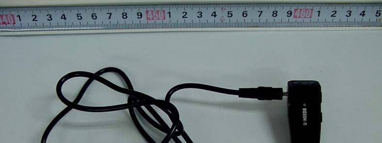
WM5UM-1100
Aug 15, 2011FHSS SPREAD SPECTRUM DEVICE (BLUETOOTH STEREO HEADSET)
Equipment Class
DSS - Part 15 Spread Spectrum Transmitter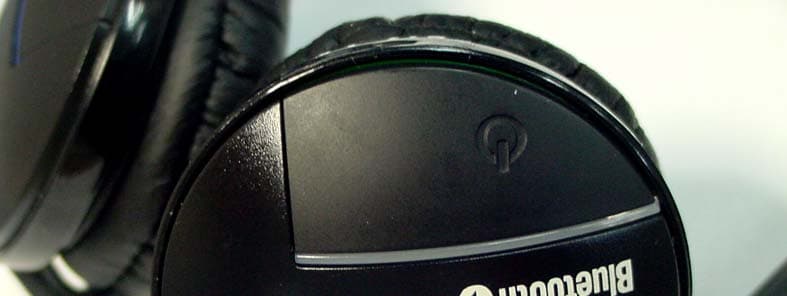
WM5UNB-2000
Aug 14, 2011FHSS SPREAD SPECTRUM DEVICE (BLUETOOTH STEREO HEADSET)
Equipment Class
DSS - Part 15 Spread Spectrum Transmitter
WM5UD-3000TV
Mar 03, 2010PART15 SPREAD SPECTRUM TRANSMITTER (AUDIO DONGLE)
Equipment Class
DSS - Part 15 Spread Spectrum Transmitter