WT7PTRKTTRM300410TRM-300 TETRA Radiomodem
Teltronic S.A.U.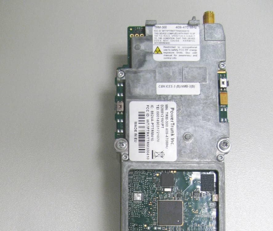
Click to zoom
Application Details
- Equipment Class
- TNB - Licensed Non-Broadcast Station Transmitter
- Date of Grant
- Jan 13, 2014
- Application Purpose
- Original Equipment
- Date of Application
- Dec 18, 2013
- Equipment Note
- TRM-300 TETRA Radiomodem
- Frequency Range
- 459.00000000 - 460.00000000
- Company
- Teltronic S.A.U.
- Country
- Spain
Documents & Files
Document Text
Text extracted from the exhibit documents filed with the FCC. Open a document above to read the original.
Users Manual
en TRM-300 TETRA Radiomodem Integration Guide Code: F070033PT Release: 05.01 © PowerTrunk Inc. TRM-300 / Integration guide F070033PT_5.1_en Page 2 of 26 en WASTE MANAGEMENT The symbol means that the product must be taken to separate collection at the product end-of life. Do not dispose of these products as unsorted municipal waste. NOTE PowerTrunk Inc. is the subsidiary of Teltronic S.A.U. responsible for business development, distribution and customer support for Teltronic’s Land Mobile Radio products in North America. The company is headquartered in New York City. Teltronic S.A.U. distributes the same products for Land Mobile Radio under different trademarks and brand names in other regions of the world. Disclaimer Although every reasonable effort has been made to ensure the accuracy of the information contained herein and any other referred document, this should not be construed as a commitment on the part of Teltronic S.A.U. and/or PowerTrunk Inc., and the liability of Teltronic S.A.U. and/or PowerTrunk Inc. for any errors and omissions shall be limited to the correction of such errors and omissions. Teltronic S.A.U. and/or PowerTrunk Inc. welcomes any comment as a way to improve any delivered documentation. The information contained herein has been prepared for the use of appropriately trained personnel, and it is intended for the purpose of the agreement under which the information is submitted. Any party using or relying upon this information assumes full responsibility for such use and in no event shall Teltronic S.A.U. and/or PowerTrunk Inc. be liable to anyone for especial, collateral, incidental, or consequential damages in connection with or arising out of the use of this information. The information or statements given in these documents regarding the suitability, capacity or performance of the mentioned hardware or software products cannot be considered binding but shall be defined in the agreement made between Teltronic S.A.U. and/or PowerTrunk Inc. and the customer. Teltronic S.A.U. and/or PowerTrunk Inc. reserves the right to revise these documents and to make changes to its content at any time, without prior notification. Copyrights No part of the information contained herein and the other referred documents may be copied, distributed or transmitted by any means to any other party without prior written permission of Teltronic S.A.U. and/or PowerTrunk Inc. The distribution of this document may be also covered by NDA (non-disclosure agreement) between Teltronic S.A.U. and/or PowerTrunk Inc. and the receiver. Please also note that part of these contents even may be covered by patent rights. This document, the referred documents and the described product are considered protected by copyright according to the applicable laws. PowerTrunk and the PowerTrunk logo are registered trademarks of Teltronic S.A.U. Copyright © PowerTrunk Inc. All rights reserved TRM-300 / Integration guide F070033PT_5.1_en Page 3 of 26 en CONTENTS 1 INTRODUCTION ........................................................................................................... 5 2 REFERENCES .............................................................................................................. 5 3 ABBREVIATIONS ......................................................................................................... 6 4 GUARANTEE ................................................................................................................ 6 5 SAFETY PRECAUTIONS ............................................................................................. 7 5.1 GENERAL ....................................................................................................................... 7 5.2 EXPOSURE TO RADIOFREQUENCY ENERGY ............................................................ 7 5.3 ELECTROMAGNETIC COMPATIBILITY ......................................................................... 7 5.4 VEHICLES ...................................................................................................................... 8 5.5 POTENTIALLY EXPLOSIVE ENVIRONMENTS .............................................................. 8 6 ESD HANDLING PRECAUTIONS ................................................................................ 9 7 PARTS REQUIRED FOR THE INTEGRATION .......................................................... 10 7.1 PARTS CONTAINED IN THE PACK ............................................................................. 10 7.2 ADDITIONAL PARTS .................................................................................................... 10 8 MECHANICAL INTEGRATION ................................................................................... 11 8.1 STANDARD MOUNTING .............................................................................................. 11 8.2 MOUNTING WITH HEATSINK ...................................................................................... 12 8.3 POWER AUXILIARY CABLE ........................................................................................ 13 8.4 CARE AND MAINTENANCE ......................................................................................... 13 9 ELECTRICAL INTEGRATION .................................................................................... 14 9.1 GROUNDING ................................................................................................................ 15 9.2 POWER SUPPLY.......................................................................................................... 15 9.3 DATA AND CONTROL INTERFACE ............................................................................. 16 9.3.1 SERIAL INTERFACE ............................................................................................................... 16 9.3.2 PROGRAMMABLE INPUT/OUTPUT INTERFACE ......................................................................... 16 9.3.3 SWITCH ON/OFF INTERFACE ..........…
Text truncated - open the document above for the full version.
Cover Letter(s)
I n s c r i t a e n e l R e g i s t r o M e r c a n t i l d e Z a r a g o z a , T o m o 2 6 6 , G e n e r a l 1 6 4 , S e c c i ó n 3 ª , L i b . S d e s . , F o l i o s 1 - 7 , H o j a 4 1 3 7 – I n s c r i p c i ó n 1 ª , F e c h a 3 0 - 8 - 7 8 – C . I . F . A - 5 0 - 0 3 5 5 1 8 TELTRONIC, S.A.UNIPERSONAL Polígono de Malpica, Calle F – Oeste 50016 ZARAGOZA Tfnos. (34) 976 46 56 56 (34) 902 41 80 16 Fax: (34) 976 46 57 20 www.teltronic.es October 1 st , 2013 FEDERAL COMMUNICATIONS COMMISSION Authorizat ion and Evaluation Divisio n 7435 Oakland Mills Road Columbia, MD 21046 Subject: Modular Approval Dear Applicant Examiner, We,TELTRONIC S.A.U., would like to have your authorization as a Limited Single Modular Approval specific to the following device: Product type or description: Land-Mobile and/or Fixed Radio Transmitter and Receiver Model:TRM-300 409-470 MHz Brand: PowerTrunk FCC ID:WT7PTRKTTRM300410 The requirements of Public Notice DA00-1407 have been met and shown on the following statements. 1. “The modular transmitter must have its own RF shielding” as it is shown in the pictures of the External Photographs document: D288Y21N1PT_EXTERNAL_DOSSIERed0100_TRM-300_409-470MHz.pdf 2. “The modular transmitter must have buffered modulation/data inputs” as it is shown in Sections 9 and 12 of the Integration Guide and in the Schematics documents: F070033PT_5.1_TRM-300_IntegrationGuide.zip D288Y21N1PT_SCHEMATICS_F072001_10.1.pdf D288Y21N1PT_SCHEMATICS_GPS_F072004_2.pdf 3. “The modular transmitter must have its own power supply regulation” as it is shown in the Circuit Descript ion document: D288Y21N1PT_CIRCUITS_DESCRIPTIONed0100_TRM-300_409-470MHz.pdf 4. “The modular transmitter must be tested in a stand-alone configuration”. The module has not been inside another device during testing for compliance with Part15 requirements. 6. “The modular transmitter must be labeled with its own FCC ID number” as it is shown in the Identification Label document: D288Y21N1PT_IDENTIFICATION_LABELSed0200_TRM-300_409-470MHz.pdf I n s c r i t a e n e l R e g i s t r o M e r c a n t i l d e Z a r a g o z a , T o m o 2 6 6 , G e n e r a l 1 6 4 , S e c c i ó n 3 ª , L i b . S d e s . , F o l i o s 1 - 7 , H o j a 4 1 3 7 – I n s c r i p c i ó n 1 ª , F e c h a 3 0 - 8 - 7 8 – C . I . F . A - 5 0 - 0 3 5 5 1 8 TELTRONIC, S.A.UNIPERSONAL Polígono de Malpica, Calle F – Oeste 50016 ZARAGOZA Tfnos. (34) 976 46 56 56 (34) 902 41 80 16 Fax: (34) 976 46 57 20 www.teltronic.es 7. “The modular transmitter must comply with any specific rule or operating requirements applicable to the transmitter and the manufacturer must provide adequate instructions along with the module to explain any such requirements”. The module has been tested for compliance with Part90 and Part22 requirements. All the requirements are explained in Section 12 of the Integration Guide that is provided with the equipment: F070033PT_5.1_TRM-300_IntegrationGuide.zip 8. “The modular transmitter must comply with any applicable RF exposure requirements”. The module has been tested for compliance with Part90 and Part22 requirements. Sincerely, Jose Roman Gimeno Certifications & Services Area Manager
Cover Letter(s)
I n s c r i t a e n e l R e g i s t r o M e r c a n t i l d e Z a r a g o z a , T o m o 2 6 6 , G e n e r a l 1 6 4 , S e c c i ó n 3 ª , L i b . S d e s . , F o l i o s 1 - 7 , H o j a 4 1 3 7 – I n s c r i p c i ó n 1 ª , F e c h a 3 0 - 8 - 7 8 – C . I . F . A - 5 0 - 0 3 5 5 1 8 TELTRONIC, S.A.UNIPERSONAL Polígono de Malpica, Calle F – Oeste 50016 ZARAGOZA Tfnos. (34) 976 46 56 56 (34) 902 41 80 16 Fax: (34) 976 46 57 20 www.teltronic.es FCC Long Term Confidentiality Request Letter October 1 st , 2013 MET Laboratories, Inc. 914 West Patapsco Avenue Baltimore, MD 21230 RE: CONFIDENTIALITY REQUEST FOR EUT:TRM-300 409-470 MHzAND FCC ID: WT7PTRKTTRM300410 To whom it may concern: This letter serves as an official request for confidentiality under sections 0.457 and 0.459 of CFR 47. We have requested that the items listed below required to be submitted with this application be permanently withheld from public review Exhibit TypeFile Name Theory of Operation/Technical Description Features Reference Guide: D280000_RG91ed0100_TRM-300_Features.pdf Procedure to carry out tests: D280000_RG90ed0201_Laboratory_Measurements.pdf Reference Guide for TDMA: D280000_RG93ed0101_TDMA.pdf Block Diagrams D288Y21N1PT_BLOCK_DIAGRAMSed0100_TRM-300_409-470MHz.pdf Circuits Description D288Y21N1PT_CIRCUITS_DESCRIPTIONed0100_TRM-300_409-470MHz.pdf Part Lists D288Y21N1PT_PART_LIST_E288Y10_10.2.pdf D288Y21N1PT_PART_LIST_GPS_F072004_2.pdf Schematics D288Y21N1PT_SCHEMATICS_F072001_10.1.pdf D288Y21N1PT_SCHEMATICS_GPS_F072004_2.pdf The above materials contain proprietary and confidential information not customarily released to the public. The public disclosure of these materials provides unjustified benefits to its competitors in the market. We hereby certify that the documentation provided to the said agent properly describes the device and/or systems for which the certification is sought. Sincerely, Jose Roman Gimeno Certifications & Services Area Manager
Cover Letter(s)
I n s c r i t a e n e l R e g i s t r o M e r c a n t i l d e Z a r a g o z a , T o m o 2 6 6 , G e n e r a l 1 6 4 , S e c c i ó n 3 ª , L i b . S d e s . , F o l i o s 1 - 7 , H o j a 4 1 3 7 – I n s c r i p c i ó n 1 ª , F e c h a 3 0 - 8 - 7 8 – C . I . F . A - 5 0 - 0 3 5 5 1 8 TELTRONIC, S.A.UNIPERSONAL Polígono de Malpica, Calle F – Oeste 50016 ZARAGOZA Tfnos. (34) 976 46 56 56 (34) 902 41 80 16 Fax: (34) 976 46 57 20 www.teltronic.es FCC Short Term Confidentiality Request Letter October 1 st , 2013 MET Laboratories, Inc. 914 West Patapsco Avenue Baltimore, MD 21230 RE: SHORT TERM CONFIDENTIALITY REQUEST FOR EUT:TRM-300 409-470 MHz AND FCC ID:WT7PTRKTTRM300410 To whom it may concern: In accordance with sections 0.457 and 0.459 of CFR 47, TELTRONIC S.A.U., requests short- term Confidentiality of following sections of this application for a period of 180 days after grant is issued. Exhibit TypeFile Name Internal Photographs D288Y21N1PT_INTERNAL_DOSSIERed0100_TRM-300_409-470MHz.pdf External Photographs D288Y21N1PT_EXTERNAL_DOSSIERed0200_TRM-300_409-470MHz.pdf Manual/Installation Guide F070033PT_5.1_TRM-300_IntegrationGuide.zip These documents contain detailed system and equipment descriptions and related information about the product, which TELTRONIC S.A.U. considers to be proprietary, confidential, and a custom design and otherwise, would not release to the general public. Since this design is a basis from which future technological products will evolve, TELTRONIC S.A.U. feels that this information would be of benefit to its competitors, and that the disclosure of the information in these documents would give our competitors an unfair advantage in the market. Sincerely, Jose Roman Gimeno Certifications & Services Area Manager
External Photos
DOSSIER – TRM-300 EXTERNAL PHOTOGRAPHS CONFIDENTIALPage 1 of 11 DOSSIER TRM-300 EXTERNAL PHOTOGRAPHS DOSSIER – TRM-300 EXTERNAL PHOTOGRAPHS CONFIDENTIALPage 2 of 11 CONTENTS 1PHOTOGRAPHS OF THE TRM-300 WITH A STANDARD MOUNTING ......................................... 3 1.1UPPERSIDE..................................................................................................................................... 3 1.2LEFTSIDE ....................................................................................................................................... 4 1.3RIGHTSIDE ..................................................................................................................................... 5 1.4LOWERSIDE ................................................................................................................................... 6 1.5FRONTSIDE .................................................................................................................................... 7 1.6BACKSIDE ...................................................................................................................................... 7 2PHOTOGRAPHS OF THE TRM-300 MOUNTED ON THE ACCESORY “THERMAL DISSIPATOR KIT”........................................................................................................................................................... 8 2.1UPPERSIDE..................................................................................................................................... 8 2.2LEFTSIDE ....................................................................................................................................... 9 2.3RIGHTSIDE ..................................................................................................................................... 9 2.4LOWERSIDE ................................................................................................................................. 10 2.5FRONTSIDE .................................................................................................................................. 11 2.6BACKSIDE .................................................................................................................................... 11 DOSSIER – TRM-300 EXTERNAL PHOTOGRAPHS CONFIDENTIALPage 3 of 11 1PHOTOGRAPHS OF THE TRM-300 WITH A STANDARD MOUNTING 1.1 UPPER SIDE DOSSIER – TRM-300 EXTERNAL PHOTOGRAPHS CONFIDENTIALPage 4 of 11 1.2 LEFT SIDE DOSSIER – TRM-300 EXTERNAL PHOTOGRAPHS CONFIDENTIALPage 5 of 11 1.3 RIGHT SIDE DOSSIER – TRM-300 EXTERNAL PHOTOGRAPHS CONFIDENTIALPage 6 of 11 1.4 LOWER SIDE DOSSIER – TRM-300 EXTERNAL PHOTOGRAPHS CONFIDENTIALPage 7 of 11 1.5 FRONT SIDE 1.6 BACK SIDE DOSSIER – TRM-300 EXTERNAL PHOTOGRAPHS CONFIDENTIALPage 8 of 11 2PHOTOGRAPHS OF THE TRM-300 MOUNTED ON THE ACCESORY “THERMAL DISSIPATOR KIT” 2.1 UPPER SIDE DOSSIER – TRM-300 EXTERNAL PHOTOGRAPHS CONFIDENTIALPage 9 of 11 2.2 LEFT SIDE 2.3 RIGHT SIDE DOSSIER – TRM-300 EXTERNAL PHOTOGRAPHS CONFIDENTIALPage 10 of 11 2.4 LOWER SIDE DOSSIER – TRM-300 EXTERNAL PHOTOGRAPHS CONFIDENTIALPage 11 of 11 2.5 FRONT SIDE 2.6 BACK SIDE
ID Label/Location Info
TRM-300 409-470 MHz IDENTIFICATION LABELS 01.01.00/1 Rev.1 PRODUCT:TRM-300 409-470 MHz CODE: D288Y21N1PT VERSION: 03 REVISION: 00 DATE: 19/11/2013 CLASSIFICATION: General information Internal document DOCUMENT MAINTENANCE THIS DOCUMENT HAS 5 PAGES EDIT.DATEAUTHORDESCRIPTION 1.0 2.0 29/06/2012 05/11/2013 Juan Luis Romera Juan Luis Romera First release. Changes in the TRM-300 identifying label: 1) Code “MN:” added before TRM-300 name. 2) Symbol “:” added before “IC” and “FCC ID”. 3.020/11/2013Juan Luis RomeraICES-003 Compliance Label added. TRM-300 409-470 MHz IDENTIFICATION LABELS Code:TRM-300_IDLABEL_410 Date: 20/11/2013Page:2 of 5 01.01.00/1 Rev.1 PowerTrunk Inc. is the subsidiary of Teltronic S.A.U. responsible for business development, distribution and customer support for Teltronic’s Land Mobile Radio products in North America. The company is headquartered in New York City. Teltronic S.A.U. distributes the same products for Land Mobile Radio under different trademarks and brand names in other regions of the world. Disclaimer Although every reasonable effort has been made to ensure the accuracy of the information contained herein and any other referred document, this should not be construed as a commitment on the part of Teltronic S.A.U. and/or PowerTrunk Inc., and the liability of Teltronic S.A.U. and/or PowerTrunk Inc. for any errors and omissions shall be limited to the correction of such errors and omissions. Teltronic S.A.U. and/or PowerTrunk Inc. welcomes any comment as a way to improve any delivered documentation. The information contained herein has been prepared for the use of appropriately trained personnel, and it is intended for the purpose of the agreement under which the information is submitted. Any party using or relying upon this information assumes full responsibility for such use and in no event shall Teltronic S.A.U. and/or PowerTrunk Inc. be liable to anyone for especial, collateral, incidental, or consequential damages in connection with or arising out of the use of this information. The information or statements given in these documents regarding the suitability, capacity or performance of the mentioned hardware or software products cannot be considered binding but shall be defined in the agreement made between Teltronic S.A.U. and/or PowerTrunk Inc. and the customer. Teltronic S.A.U. and/or PowerTrunk Inc. reserves the right to revise these documents and to make changes to its content at any time, without prior notification. Copyrights No part of the information contained herein and the other referred documents may be copied, distributed or transmitted by any means to any other party without prior written permission of Teltronic S.A.U. and/or PowerTrunk Inc. The distribution of this document may be also covered by NDA (non- disclosure agreement) between Teltronic S.A.U. and/or PowerTrunk Inc. and the receiver. Please also note that part of these contents even may be covered by patent rights. This document, the referred documents and the described product are considered protected by copyright according to the applicable laws. PowerTrunk and the PowerTrunk logo are registered trademarks of Teltronic S.A.U. Copyright © PowerTrunk Inc. All rights reserved. TRM-300 409-470 MHz IDENTIFICATION LABELS Code:TRM-300_IDLABEL_410 Date: 20/11/2013Page:3 of 5 01.01.00/1 Rev.1 CONTENTS: 1.INTRODUCTION ......................................................................................................... 4 2.LABELS ...................................................................................................................... 4 3.LOCATION OF THE LABELS .................................................................................... 5 TRM-300 409-470 MHz IDENTIFICATION LABELS Code:TRM-300_IDLABEL_410 Date: 20/11/2013Page:4 of 5 01.01.00/1 Rev.1 1. INTRODUCTION There are three identification labels that are located on the front part of the TRM-300 409-470 MHz. 2. LABELS Label 1: Material: Polyester film laminate. Colour: Silver and Black. Label 2: Material: Polyester film laminate. Colour: Silver, black and yellow. Label 3: Material: Polyester film laminate. Colour: Silver and Black. TRM-300 409-470 MHz IDENTIFICATION LABELS Code:TRM-300_IDLABEL_410 Date: 20/11/2013Page:5 of 5 01.01.00/1 Rev.1 3. LOCATION OF THE LABELS Location of the labels LABEL 2 HERE L A B E L 1 H E R E LABEL 3 HERE
Internal Photos
DOSSIER – TRM-300 INTERNAL PHOTOGRAPHS CONFIDENTIALPage 1 of 5 DOSSIER TRM-300 TRM-300 INTERNAL PHOTOGRAPHS DOSSIER – TRM-300 INTERNAL PHOTOGRAPHS CONFIDENTIALPage 2 of 5 CONTENTS 1TRM-300 PRINTED CIRCUIT BOARD PHOTOGRAPHS ................................................................... 3 1.1MAINBOARD,TOP........................................................................................................................... 3 1.2MAINBOARD,BOTTOM .................................................................................................................. 4 1.3GPSBOARD,TOP .............................................................................................................................. 5 1.4GPSBOARD,BOTTOM ..................................................................................................................... 5 DOSSIER – TRM-300 INTERNAL PHOTOGRAPHS CONFIDENTIALPage 3 of 5 1TRM-300 PRINTED CIRCUIT BOARD PHOTOGRAPHS 1.1 MAIN BOARD, TOP DOSSIER – TRM-300 INTERNAL PHOTOGRAPHS CONFIDENTIALPage 4 of 5 1.2 MAIN BOARD, BOTTOM DOSSIER – TRM-300 INTERNAL PHOTOGRAPHS CONFIDENTIALPage 5 of 5 1.3 GPS BOARD, TOP 1.4 GPS BOARD, BOTTOM
RF Exposure Info
RF Exposure RF Exposure Requirements: §1.1307(b)(1) and §1.1307(b)(2): Systems operating under the provisions of this section shall be operated in a manner that ensures that the public is not exposed to radio frequency energy levels in excess of the Commission’s guidelines. §2.1091 Radio frequency radiation exposure evaluation: mobile devices RF Radiation Exposure Limit: §1.1310: As specified in this section, the Maximum Permissible Exposure (MPE) Limit shall be used to evaluate the environmental impact of human exposure to radiofrequency (RF) radiation as specified in Sec. 1.1307(b), except in the case of portable devices which shall be evaluated according to the provisions of Sec. 2.1093 of this chapter. RSS-102 Requirement: Devices that have a radiating element normally operating at separation distances greater than 20 cm between the user and the device shall undergo an RF exposure evaluation. RF exposure evaluation shall be made in accordance with the latest version of IEEE C95.3. For the purpose of this standard, Industry Canada has adopted the SAR and RF field strength limits established in Health Canada’s RF exposure guideline, Safety Code 6. Test Results: Equipment complies with this Section. Test Engineer(s): Len Knight Test Date(s): 09/27/13 FCC - Limits for Maximum Permissible Exposure (MPE) Requirements: FCC Guidelines for evaluating exposure to RF Emissions, from the FCC OET Bulletin 65, Evaluating Compliance with FCC Guidelines for Human Exposure to Radiofrequency Electromagnetic Fields. IC – RF Field Strength Limits for Devices Used by the General Public (Uncontrolled Environment) Frequency Range (MHz) Electric Field (V/m rms) Magnetic Field (A/m rms) Power Density (W/m 2 ) Averaging Time (minutes) 0.003-1 280 2.19 - 6 1-10 280/f 2.19/f - 6 10-30 28 2.19/f - 6 30-300 28 0.073 2* 6 300-1500 1.585f 0.5 0.0042f 0.5 f / 150 6 1500-15000 61.4 0.163 10 6 15000-150000 61.4 0.163 10 616000 / f 1.2 150000-300000 0.158f 0.5 4.21 x 10 -4 f 0.5 6.67 x 10 -5 f 616000 / f 1.2 Note: f is frequency in MHz. * Power density limit is applicable at frequencies greater than 100 MHz. IC - RF Field Strength Limits for Controlled Devices (Controlled Environment) Frequency Range (MHz) Electric Field (V/m rms) Magnetic Field (A/m rms) Power Density (W/m 2 ) Averaging Time (minutes) 0.003-1 600 4.9 - 6 1-10 600/f 4.9/f - 6 10-30 60 4.9/f - 6 30-300 60 0.163 10* 6 300-1500 3.54f 0.5 0.0094f 0.5 f / 30 6 1500-15000 137 0.364 50 6 15000-150000 137 0.364 50 616000 / f 1.2 150000-300000 0.354f 0.5 9.4 x 10 -4 f 0.5 3.33 x 10 -5 f 616000 / f 1.2 Note: f is frequency in MHz. * Power density limit is applicable at frequencies greater than 100 MHz. Procedures: Prior to radiated testing, the radio was connected to a power meter in order to see if any channel was significantly stronger than the rest for each band. For the purposes of testing, the channel with the highest power from each band was used. Test Procedures: 1. The test setup was as described in the EUT Configuration section of this test report. The TETRA signal generator was on the outside of the chamber while the antenna was on the inside. 2. The antenna under test was mounted to a 30x30cm ground plane and placed on an 80cm test table. 3. The EUT was set to transmit continuously at the selected frequency and modulation at maximum RF power. The distance between the field intensity probe and the EUT’s antenna was 20 cm since the calculated distance for uncontrolled environments was R < 20 cm. 4. Field intensity measurements were taken at different heights of the probe from the ground (0.1 to 2 meters) in 10cm increments, while rotating versus azimuth (from 0° to 360°). 5. Each maximized peak field intensity measurement was recorded. 6. Raw field strength was corrected with the field intensity probe correction factors. 7. The corrected field strength in V/m was converted to power density using the formula: S = E 2 / Z o where Z o = 120 π ≈ 377 Ω 8. Average values of power density were calculated for the imaginary whole human body (0.1–2.0 m), for the lower part of the body (0.1–0.9 m) and for the upper part of the body (1.0–2.0 m). The results of calculations are shown in the following tables. Calculation for Part 90 TI D-LMR 409-430 MHz highest conducted power = 33.06 dBm (429.9875 MHz), therefore, Limit for Controlled Exposure: 1.43 mW/cm 2 EUT maximum antenna gain = 8 dBi. Equation from page 18 of OET 65, Edition 97-01 S = PG / 4R 2 or R = √PG / 4S where, S = Power Density P = Power Input to antenna (2023.02 mW) G = Antenna Gain (6.31 numeric) D.C. = Duty Cycle (25%) R = 25 cm S = (D.C.)(P)(G) / 4πR 2 S = (0.25)(2023.02)(6.31) / 4π625 S = 0.4 mW/cm 2 Calculation for RSS-119 TETRA 409-430 MHz highest conducted power = 35.48 dBm (409.09375 MHz), therefore, Limit for Controlled Exposure: 1.36 mW/cm 2 EUT maximum antenna gain = 8 dBi. Equation from page 18 of OET 65, Edition 97-01 S = PG / 4R 2 or R = √PG / 4S where, S = Power Density P = Power Input to antenna (3531.8 mW) G = Antenna Gain (6.31 numeric) D.C. = Duty Cycle (25%) R = 25 cm S = (D.C.)(P)(G) / 4πR 2 S = (0.25)( 3531.8)(6.31) / 4π625 S = 0.71 mW/cm 2 Calculation for Part 22 TI D-LMR 454 - 460 MHz highest conducted power = 33.04 dBm (454.05 MHz), therefore, Limit for Controlled Exposure: 1.51 mW/cm 2 EUT maximum antenna gain = 8 dBi. Equation from page 18 of OET 65, Edition 97-01 S = PG / 4R 2 or R = √PG / 4S where, S = Power Density P = Power Input to antenna (2013.7 mW) G = Antenna Gain (6.31 numeric) D.C. = Duty Cycle (25%) R = 25 cm S = (D.C.)(P)(G) / 4πR 2 S = (0.25)(2013.72)(6.31) / 4π625 S = 0.4 mW/cm 2 Calculation for Part 90 TI D-LMR 450 - 470 MHz highest conducted power = 33.07 dBm (465 MHz), therefore, Limit for Controlled Exposure: 1.5 mW/cm 2 EUT maximum antenna gain = 8 dBi. Equation from page 18 of OET 65, Edition 97-01 S = PG / 4R 2 or R = √PG / 4S where, S = Power Density P = Power Input to antenna (2027.6 mW) G = Antenna Gain (6.31 numeric) D.C. = Duty Cycle (25%) R…
Text truncated - open the document above for the full version.
Test Report
MET Laboratories, Inc. Safety Certification - EMI - Telecom Environmental Simulation 914 WEST PATAPSCO AVENUE ● BALTIMORE, MARYLAND 21230-3432 ● PHONE (410) 354-3300 ● FAX (410) 354-3313 33439 WESTERN AVENUE ● UNION CITY, CALIFORNIA 94587 ● PHONE (510) 489-6300 ● FAX (510) 489-6372 3162 BELICK STREET ● SANTA CLARA, CALIFORNIA 95054 ● PHONE (408) 748-3585 ● FAX (510) 489-6372 13301 MCCALLEN PASS ● AUSTIN, TEXAS 78753 ● PHONE (512) 287-2500 ● FAX (512) 287-2513 The Nation’s First Licensed Nationally Recognized Testing Laboratory December 13, 2013 Teltronic, S.A.U. Poligono Malpica, Calle F-Oeste 50016, Zaragoza Spain Dear José Román, Enclosed is the EMC Wireless test report for compliance testing of the Teltronic, S.A.U., TRM-300 409 - 470 MHz, tested to the requirements of Title 47 of the Code of Federal Regulations (CFR), Part 15 Subpart B and ICES-003, Issue 5 August 2012 for a Class B Digital Device, Part 90 and RSS-119, Issue 11, June 2011 for Land Mobile Radio Services, and Part 22 Subpart E for Paging and Radiotelephone Service. Thank you for using the services of MET Laboratories, Inc. If you have any questions regarding these results or if MET can be of further service to you, please feel free to contact me. Sincerely yours, MET LABORATORIES, INC. Jennifer Warnell Documentation Department Reference: (\Teltronic, S.A.U.\EMC39733-FCC 15/22/90-IC RSS-119/ICES-003 Rev. 5) Certificates and reports shall not be reproduced except in full, without the written permission of MET Laboratories, Inc. MET Laboratories, Inc. Safety Certification - EMI - Telecom Environmental Simulation 914 WEST PATAPSCO AVENUE ● BALTIMORE, MARYLAND 21230-3432 ● PHONE (410) 354-3300 ● FAX (410) 354-3313 33439 WESTERN AVENUE ● UNION CITY, CALIFORNIA 94587 ● PHONE (510) 489-6300 ● FAX (510) 489-6372 3162 BELICK STREET ● SANTA CLARA, CALIFORNIA 95054 ● PHONE (408 748-3585 ● FAX (510) 489-6372 13301 MCCALLEN PASS ● AUSTIN, TEXAS 78753 ● PHONE (512) 287-2500 ● FAX (512) 287-2513 DOC-EMC700 7/9/04 Electromagnetic Compatibility Criteria Test Report For the Teltronic, S.A.U. TRM-300 409 - 470 MHz Tested under The FCC and IC Verification Rules Contained in Title 47 of the CFR, Part 15 B and ICES-003 for a Class B Digital Device & Part 90 and RSS-119 for Private Land Mobile Radio Services & Part 22 Subpart E for Paging and Radiotelephone Service MET Report: EMC39…
Text truncated - open the document above for the full version.
Contact Information
Applicant
Jose Roman
Technical Contact
TELTRONIC S.A.U.Jose Roman Gimeno
[email protected](0034) 976 46 56 56
POLIGONO MALPICA, CALLE F-OESTE · ZARAGOZA · Spain
Test Firm
EUROFINS ELECTRICAL AND ELECTRONIC TESTING NA, INCGreg Kovolenko
Technical Specifications
| # | Rule Parts | Frequency Range | Power Output | Emission | Tolerance |
|---|---|---|---|---|---|
| 36 | 22 | 459 MHz - 460 MHz | 2.01 W | 20K0Q7D | 1 ppm |
Other Applications from Teltronic S.A.U.
WT7PTRNKTMBS760
Jan 15, 2015MBS Unit -K
Equipment Class
TNB - Licensed Non-Broadcast Station Transmitter
WT7PTHTT500760B
Apr 16, 2013Digital Handheld Terminal
Equipment Class
TNF - Licensed Non-Broadcast Transmitter Held to Face
WT7PTMDT500760B
Apr 14, 2013Land-Mobile and/or Fixed Radio Transmitter and Receiver
Equipment Class
TNB - Licensed Non-Broadcast Station Transmitter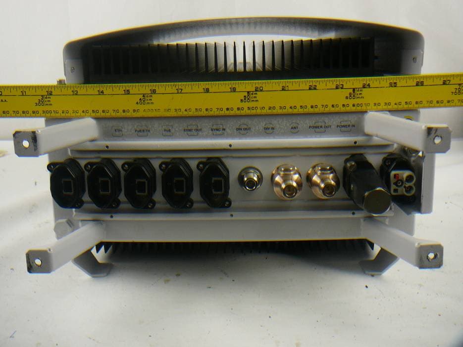
WT7PTRNKTMBS800
Jan 20, 2013MBS Unit-N Digital RF Transceiver
Equipment Class
TNB - Licensed Non-Broadcast Station Transmitter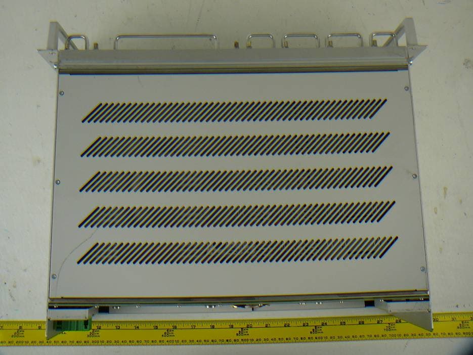
WT7PTRNKTBSR75760
Dec 20, 2012Digital RF Transceiver
Equipment Class
TNB - Licensed Non-Broadcast Station Transmitter