WU8NB24G1V2VEHICLE RADAR SENSOR, REAR CROSS TRAFFIC ALERT
Magna Electronics, LLC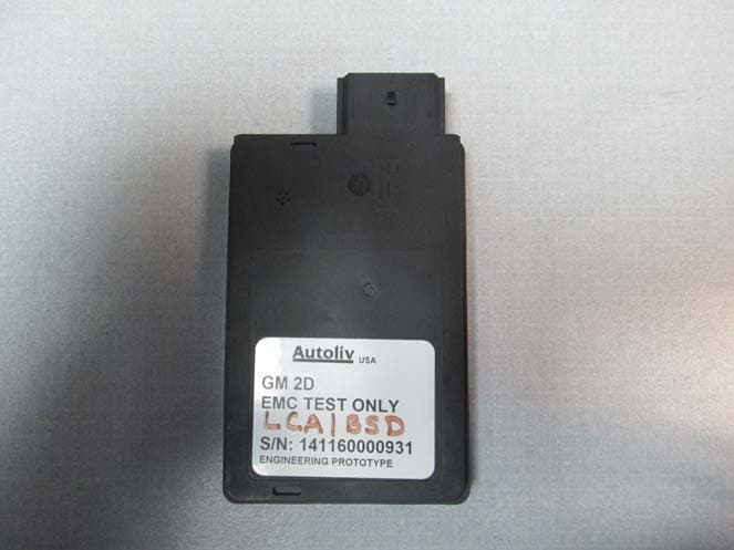
Click to zoom
Application Details
- Equipment Class
- DXX - Part 15 Low Power Communication Device Transmitter
- Date of Grant
- Mar 05, 2014
- Application Purpose
- Original Equipment
- Date of Application
- Mar 05, 2014
- Equipment Note
- VEHICLE RADAR SENSOR, REAR CROSS TRAFFIC ALERT
- Frequency Range
- 24006.00000000 - 24204.30000000
- Company
- Magna Electronics, LLC
- Country
- United States
Documents & Files
Document Text
Text extracted from the exhibit documents filed with the FCC. Open a document above to read the original.
Users Manual
REVISION HISTORY Rev Description Date Apprv’d 000 Initial Release 8/31/2011 001 Revised 3/15/2013 002 Certification Documentation SENSOR MODULE, AUTOMOTIVE RADAR, SRR, NB FCC ID/MODEL Number: WU8NB24G1V2 TITLE: Product Description, User Manual, Installation Guideline DOCUMENT NO: SENSOR MODULE, RADAR, SRR, NB PAGE 1 OF 16 Autoliv Electronics Lowell. 1011B Pawtucket Blvd. Lowell, MA 01853 ATTENTION USER OF THIS DOCUMENT IS RESPONSIBLE FOR DETERMINING CURRENT REVISION LEVEL BEFORE USING DOCUMENT. ©AUTOLIV INC. THIS DOCUMENT AND THE DATA DISCLOSED HEREIN OR HEREWITH IS FOR THE PURPOSE OF CERTIFICATION DOCUMENTATION. Product Description, User Manual, Installation Guideline Doc. No. xxxxxxxxx SENSOR MODULE, RADAR, SRR, NB Page 2 of 16 TABLE OF CONTENTS 1.0 PRODUCT OVERVIEW 4 2.0 MOUNTING ORIENTATION 4 2.1. Vehicle Orientation 4 2.2. Sensor Orientation 4 3.0 SPECIFICATION 5 3.1. Sensor characteristics 5 4.0 BLOCK DIAGRAM 6 5.0 MECHANICAL 7 5.1. Envelope dimensions, weight and connector pin-out 7 5.2. Security protection – Tamper proof features 8 5.3. Label 8 6.0 INTEGRATION AND MOUNTING GUIDELINES 9 6.1. Attachment to the vehicle 9 6.2. Detection Range / Azimuth Angle Measurement Range 9 6.3. Detection Angle Elevation 10 6.4. Installation Guidelines For Individual Sensors 11 6.4.1 Distance to bumper fascia 11 6.4.2 Effect Of Type- And Thickness Of Fascia Material 12 6.4.3 Effect of the paint 12 6.4.4 Smoothness of Fascia in Front of Antenna 12 6.5. Feature installation guidelines 13 6.5.1 Sensor Connector Orientation 13 6.5.2 Vehicle Coordinate System 13 6.5.3 Identifying the Sensor Position 13 6.5.4 Y-direction recommendation 14 6.5.5 X-direction recommendation 14 6.5.1 Sensor Azimuth Angle (X-Y Plane) 14 6.5.2 Elevation Angle recommendation 14 6.5.1 Sensor Height and Elevation Angle Settings 15 7.0 User information and Conformity to regulation 15 7.1. Required notice to the user in the USA for Part 15 Devices per FCC 15 7.2. Required notice to user in Canada per RSS-gen issue 3 15 7.3. Required notices to user in Japan 16 Product Description, User Manual, Installation Guideline Doc. No. xxxxxxxxx SENSOR MODULE, RADAR, SRR, NB Page 3 of 16 LIST OF FIGURES Figure 1. Vehicle Orientation 4 Figure 2 : Radar Orientation 4 Figure 3 : Block Diagram 6 Figure 4 : Envelope Drawing 7 Figure 5 : Label Drawing 8 Figure 6 : Bracket Retention Features 9 Figure 7 : Azimuth Detection zone 10 Figure 8 : Azimuth keep out zone 10 Figure 9 : Elevation keep out zone 11 Figure 10 : Azimuth and Elevation Keep out zones 11 Figure 11 : Distance to bumper fascia 11 Figure 12 : Character lines 12 Figure 13 : Vehicle coordinate system 13 Figure 14 : Sensor position 14 Product Description, User Manual, Installation Guideline Doc. No. xxxxxxxxx SENSOR MODULE, RADAR, SRR, NB Page 4 of 16 1.0 PRODUCT OVERVIEW This system is designed to provide the Blind Spot Detection, Lane Change Assist and Rear Cross Traffic warning features as defined by the ISO17387. It relies on two standalone 24GHz narrow band radar sensors located in the rear corners of the vehicle. This radar complies with the low power 24 GHz narrow band regulations (also known as low power non-specific short range or “ISM”) of most countries such as European CEPT community, USA, Canada, China, Brazil and Japan. The sensor has two modes of operations: It operates in a Blind Spot Detection & Lane Change Assist mode when the vehicle is in forward gear or standstill and switches to a Rear Cross Traffic Alert mode when the vehicle is operating in reverse. The sensor generates three different waveforms. Blind Spot Detection is optimized for very near range detection (sub 10m), Lane Change Assist is optimized for mid-range up (70m) and Rear Cross Traffic Alert is optimized for short range detection (40m). 2.0 MOUNTING ORIENTATION 2.1. Vehicle Orientation The sensor is mounted behind a plastic fascia squinted 50deg towards the rear. Figure 1. Vehicle Orientation 2.2. Sensor Orientation The connector must be facing towards the rear of the vehicle and the sensor boresight is facing the fascia outwards. Figure 2 : Radar Orientation 0 deg bore-sight Horizontal/Azimuth 0deg UP Vertical 50deg Forward Product Description, User Manual, Installation Guideline Doc. No. xxxxxxxxx SENSOR MODULE, RADAR, SRR, NB Page 5 of 16 3.0 SPECIFICATION 3.1. Sensor characteristics Limits Comments External interface Operating Temperature ‐40C to +85C External Ambient temperature Input Voltage, operating 6.0‐16.0 VDC Input current (/power) 0.350 A max I*V ~ constant @ <4 W Operating Life 15 yrs. Automotive standard Vehicle network interface CAN 2.0B Automotive standard Digital DSP Processor Clock(s) 30.0 MHz +/‐100ppm Internal PLL to 150MHz Host Processor 30.0 MHz +/‐100ppm Internal PLL to 60Mhz CAN baud rate 25 kbps to 1Mbps Com baud rate is SW configurable LED Drive current 40‐60 mA Short‐circuit current limited (<120mA) RF in BSD mode Occupied Bandwidth 24.150 ‐ 24.250GHz (ISM) See Type Approval Radio test report Power Output, Transmit +13 dBm peak in any direction Tx patterns – elevation +/‐11 deg At ‐6 dB points ‐azimuth > ‐40 to +40 degrees Search range 0.5 m – 14 m Range Accuracy +/‐ 20 cm Angle Accuracy +/‐ 5 deg Within +/‐ 40 deg FOV Speed Accuracy +/‐ 5 km/hr RF in LCA mode Occupied Bandwidth 24.050 ‐ 24.250GHz (ISM) See Type Approval Radio test report Power Output, Transmit +15 dBm peak pulse in any direction Tx patterns – elevation +/‐11 deg At ‐6 dB points ‐ azimuth > ‐40 to +40 degrees Search range 4 m – 80 m Range Accuracy +/‐ 50cm Angle Accuracy +/‐ 2 deg Speed Accuracy +/‐ 2 km/hr RF in RCTA mode Occupied Bandwidth 24.050 ‐ 24.250GHz (ISM) See Type Approval Radio test report Power Output, Transmit +15 dBm peak pulse in any direction Tx patterns – elevation +/‐10 deg At ‐6 dB points ‐ azimuth > ‐40 to +40 degrees Search range 2 m – 60m Range Accuracy +/‐ 50 cm Angle Accuracy +/‐ 5 deg Speed Accuracy +/‐ 2 km/h Antenna Polarization Linear Vertical RF Oscillator 60 MHz +/‐ 100 ppm Tabl…
Text truncated - open the document above for the full version.
Cover Letter(s)
Autoliv ASP, Inc. Autoliv Active Safety Radar 1001 Pawtucket Blvd. P.O. Box 1858 Lowell, Massachusetts, USA 01853 February 12, 2014 To Whom It May Concern: Subject: Authorization of Compliance Worldwide to Act on Autoliv ASP, Inc.’s behalf Please be advised that Jeff Schaefer of Autoliv ASP, Inc. authorizes Larry K. Stillings, President of Compliance Worldwide Inc. to act on our behalf, until otherwise notified for applications submitted for the purpose of obtaining an FCC Grant of Equipment Authorization for FCC ID: WU8NB24G1V2. We certify that we are not subject to denial of federal benefits that includes FCC benefits, pursuant to Section 5301 of the Anti-Drug Abuse ACT of 1988, U.S.C 862. Further no party, as defined in 47 CFR 1.2002(b), to the application is subject to denial of federal benefits, that includes FCC benefits. Thank you for your attention to this matter Signatory: Jeff Schaefer Engineering Manager Autoliv ASP,Inc. 1001 Pawtucket Blvd. Lowell , MA USA 01854 March 4, 2014 Page 2
External Photos
External Photos WU8NB24G1V2 Product Photographs – Front Product Photographs – Back (LCA/BSD) Product Photographs – Back (RCTA/BSD) Product Photographs – Profile Product Photographs – Profile
ID Label/Location Info
PLM: Part Drawing 6266260 000 Released on 2012-10-04
Internal Photos
© Autoliv, Inc. All Rights Reserved. / EXTERNAL/ AEL-BDL-022014 / WU8NB24G1V2.pdf - 1 Internal Photos – RF layer WU8NB24G1V2
RF Exposure Info
Test Number: 128-14R1 Issue Date: 2/6/2014 Page 40 of 47 6. Measurement Data (continued) 6.8. Public Exposure to Radio Frequency Energy Levels (15.247(i) (1.1307 (b)(1)) RSS-GEN 5.5, RSS 102 6.8.1. Note: The following equation is used to determine the output power from the measured worst case field strength: (E x d) 2 P = (30 x G) P = the power in Watts. E = the measured maximum field in V/m G = the numeric gain of the transmitting antenna over an isotropic radiator. d = the distance in meters of the field strength measurement. Frequency Peak Field Strength Distance Antenna Gain 1 Measured Output Power Channel (GHz) (dBμV/m) (m) (dBi) (mW) LCA 24.060390 105.55 3.0 12.200 0.649 BSD 24.200005 106.07 3.0 12.200 0.731 RCTA 24.060390 108.48 3.0 12.200 1.274 RCTA 24.200400 109.26 3.0 12.200 1.524 Power Density Channel MPE Distance (cm) DUT Output Power (dBm) DUT Antenna Gain (dBi) (mW/cm 2 ) (W/m 2 ) Limit (mW/cm²) Result (1) (2) (3) (4) (5) LCA 20 -1.88 12.20 0.0021422 0.0214216 1 Compliant BSD 20 -1.36 12.20 0.0024146 0.0241463 1 Compliant RCTA 20 1.05 12.20 0.0042058 0.0420583 1 Compliant RCTA 20 1.83 12.20 0.0050333 0.0503328 1 Compliant Compliance Worldwide, Inc. - 357 Main Street - Sandown, NH 03873 (603) 887 3903 Fax 887 6445 http://www.cw-inc.com PD = Power Density (mW/cm2) OP + AG (4 x π x d²) PD = OP = DUT Output Power (dBm) AG = DUT Antenna Gain (dBi) d = MPE Distance (cm) 1. Reference CFR 2.1093(b): For purposes of this section, a portable device is defined as a transmitting device designed to be used so that the radiating structure(s) of the device is/are within 20 centimeters of the body of the user. 2. Sections 6.2 of this test report. 3. Antenna gain data provided by the client. 4. Power density is calculated from field strength measurement and antenna gain. 5. Reference CFR 1.1310, Table 1: Limits for Maximum Permissible Exposure (MPE), Section (B): Limits for General Population/Uncontrolled Exposure.
Test Report
Compliance Worldwide, Inc. - 357 Main Street - Sandown, NH 03873 COMPLIANCE WORLDWIDE INC. TEST REPORT 128-14R2 In Accordance with the Requirements of Federal Communications Commission CFR Title 47 Part 15.249, Subpart C Industry Canada RSS 310 Low Power License-Exempt Radio Communication Devices Intentional Radiators Issued to Autoliv Active Safety 1001 Pawtucket Blvd Lowell, MA 01854 978-674-6500 For the 24 GHz GM Sensor LCA/BSD & RCTA/BSD Modes Autoliv Part Number: 625566400E FCC ID: WU8NB24G1V2 IC: CANADA 310 Report Issued on February 6, 2014 Revisions R2 Issued on February 27, 2014 Tested by This test report shall not be reproduced, except in full, without written permission from Compliance Worldwide, Inc. (603) 887 3903 Fax 887 6445 http://www.complianceworldwide.com Test Number: 128-14R2 Issue Date: 2/27/2014 Page 2 of 55 Compliance Worldwide, Inc. - 357 Main Street - Sandown, NH 03873 (603) 887 3903 Fax 887 6445 http://www.cw-inc.com Table of Contents 1. Scope .................................................................................................................................. 3 2. Product Details.................................................................................................................... 3 2.1. Manufacturer ..............................................................................................................3 2.2. Model Number............................................................................................................ 3 2.3. Serial Number ............................................................................................................ 3 2.4. Description ................................................................................................................. 3 2.5. Power Source............................................................................................................. 3 2.6. EMC Modifications ..................................................................................................... 3 3. Product Configuration ......................................................................................................... 3 3.1. Support Equipment .................................................................................................... 3 3.2. Cables ........................................................................................................................ 3 3.3. Operational Characteristics & Software ..................................................................... 3 3.4. Block Diagram ............................................................................................................ 3 4. Measurements Parameters................................................................................................. 4 4.1. Measurement Equipment Used to Perform Test ........................................................ 4 4.2. Measurement & Equipment Setup ............................................................................. 5 4.3. Measurement Procedure............................................................................................ 5 4.4. Choice of Operating Frequencies .............................................................................. 5 5. Measurement Summary...................................................................................................... 6 6. Measurement Data.............................................................................................................. 7 6.1. Antenna Requirement ................................................................................................ 7 6.2. Radiated Field Strength of Fundamental ................................................................... 8 6.3. Radiated Field Strength of Harmonics ..................................................................... 11 6.4. Band Edge Measurements....................................................................................... 17 6.5. Spurious Radiated Emissions .................................................................................. 23 6.6. 26 dB Bandwidth ..................................................................................................... 42 6.7. 99% Bandwidth ........................................................................................................ 44 6.8. Public Exposure to Radio Frequency Energy Levels ............................................... 46 7. Test Images ...................................................................................................................... 47 7.1. Spurious and Harmonic Emissions - Front............................................................... 47 7.2. Spurious and Harmonic Emissions Below 30 MHz - Rear ....................................... 48 7.3. Spurious and Harmonic Emissions 30 MHz to 1 GHz - Rear................................... 49 7.4. Spurious and Harmonic Emissions 1 to 18 GHz - Front........................................... 50 7.5. Spurious and Harmonic Emissions 18 to 40 GHz - Front......................................... 51 7.6. Spurious and Harmonic Emissions 40 to 50 GHz (48 GHz - Front) ......................... 52 7.7. Spurious and Harmonic Emissions 50 to 75 GHz (72 GHz - Side) .......................... 53 7.8. Spurious and Harmonic Emissions 75 to 100 GHz (Side)........................................ 54 8. Test Site Description ......................................................................................................... 55 Test Number: 128-14R2 Issue Date: 2/27/2014 Page 3 of 55 1. Scope This test report certifies that the Autoliv Electronics 24 GHz NB LCA/BSD/RCTA Mode Sensor, as tested, meets the FCC Part 15, Subpart C and Industry Canada RSS 310, Section 3.10 requirements. The scope of this test report is limited to the test sample provided by the client, only in as much as that sample represents other production units. If any significant changes are made to the unit, t…
Text truncated - open the document above for the full version.
Test Setup Photos
Test Number: 128-14R2 Issue Date: 2/27/2014 7. Test Images 7.1. Spurious and Harmonic Emissions – Front Page 47 of 55 Compliance Worldwide, Inc. - 357 Main Street - Sandown, NH 03873 (603) 887 3903 Fax 887 6445 http://www.cw-inc.com Test Number: 128-14R2 Issue Date: 2/27/2014 7. Test Images 7.2 Spurious and Harmonic Emissions Below 30 MHz – Rear Page 48 of 55 Compliance Worldwide, Inc. - 357 Main Street - Sandown, NH 03873 (603) 887 3903 Fax 887 6445 http://www.cw-inc.com Test Number: 128-14R2 Issue Date: 2/27/2014 7. Test Images 7.3. Spurious and Harmonic Emissions – Rear – 30 MHz to 1 GHz Page 49 of 55 Compliance Worldwide, Inc. - 357 Main Street - Sandown, NH 03873 (603) 887 3903 Fax 887 6445 http://www.cw-inc.com Test Number: 128-14R2 Issue Date: 2/27/2014 7. Test Images 7.4. Spurious and Harmonic Emissions – Front - 1 to 18 GHz Page 50 of 55 Compliance Worldwide, Inc. - 357 Main Street - Sandown, NH 03873 (603) 887 3903 Fax 887 6445 http://www.cw-inc.com Test Number: 128-14R2 Issue Date: 2/27/2014 7. Test Images 7.5. Spurious and Harmonic Emissions – Front - 18 to 40 GHz Page 51 of 55 Compliance Worldwide, Inc. - 357 Main Street - Sandown, NH 03873 (603) 887 3903 Fax 887 6445 http://www.cw-inc.com Test Number: 128-14R2 Issue Date: 2/27/2014 7. Test Images 7.6. Spurious and Harmonic Emissions – Front – 40 to 50 GHz Page 52 of 55 Compliance Worldwide, Inc. - 357 Main Street - Sandown, NH 03873 (603) 887 3903 Fax 887 6445 http://www.cw-inc.com Test Number: 128-14R2 Issue Date: 2/27/2014 7. Test Images 7.7. Spurious and Harmonic Emissions – Side – 50 to 75 GHz Page 53 of 55 Compliance Worldwide, Inc. - 357 Main Street - Sandown, NH 03873 (603) 887 3903 Fax 887 6445 http://www.cw-inc.com Test Number: 128-14R2 Issue Date: 2/27/2014 7. Test Images 7.8. Spurious and Harmonic Emissions – Side – 75 to 100 GHz Page 54 of 55 Compliance Worldwide, Inc. - 357 Main Street - Sandown, NH 03873 (603) 887 3903 Fax 887 6445 http://www.cw-inc.com
Contact Information
Applicant
Kim Mooney(Director, Radar Platforms)
Test Firm
Compliance Worldwide, Inc.Deb Bourbeau
Technical Specifications
| # | Rule Parts | Frequency Range | Power Output |
|---|---|---|---|
| 1 | 15C | 24.01 GHz - 24.20 GHz | - |
Other Applications from Magna Electronics, LLC
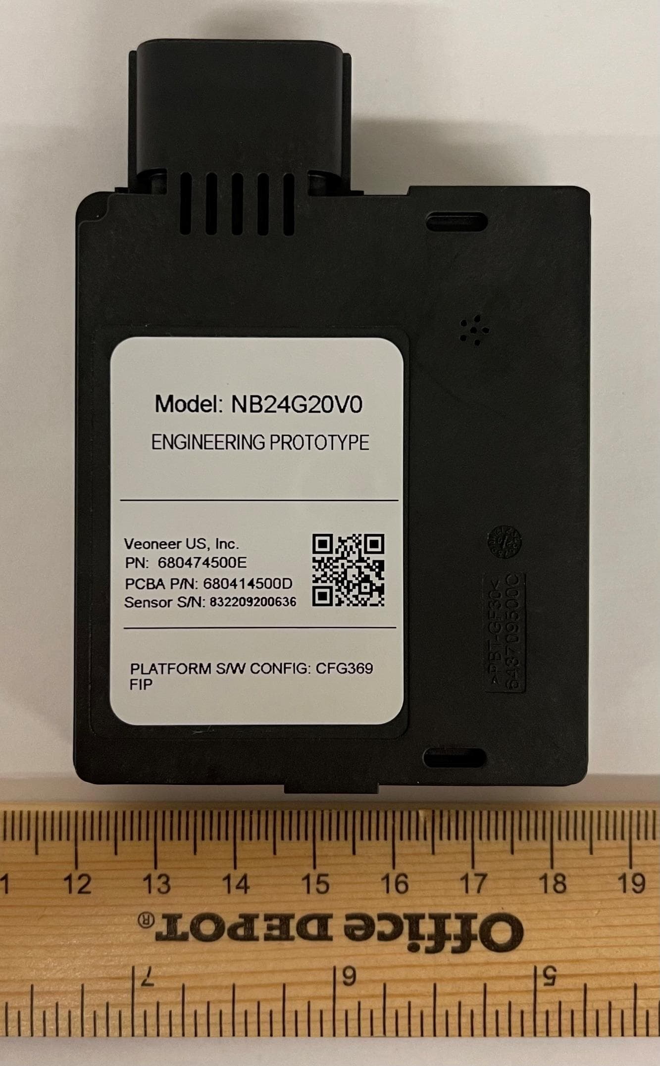
WU8NB24G20V0
May 18, 202124 GHz NB automotive radar
Equipment Class
DXX - Part 15 Low Power Communication Device Transmitter
WU877V125CRN
Apr 28, 202177 GHz CRN Radar Sensor
Equipment Class
VRD - Part 95 Vehicular Radar Systems
WU877V13CRN
Aug 24, 2020CRN Radar Sensor
Equipment Class
VRD - Part 95 Vehicular Radar Systems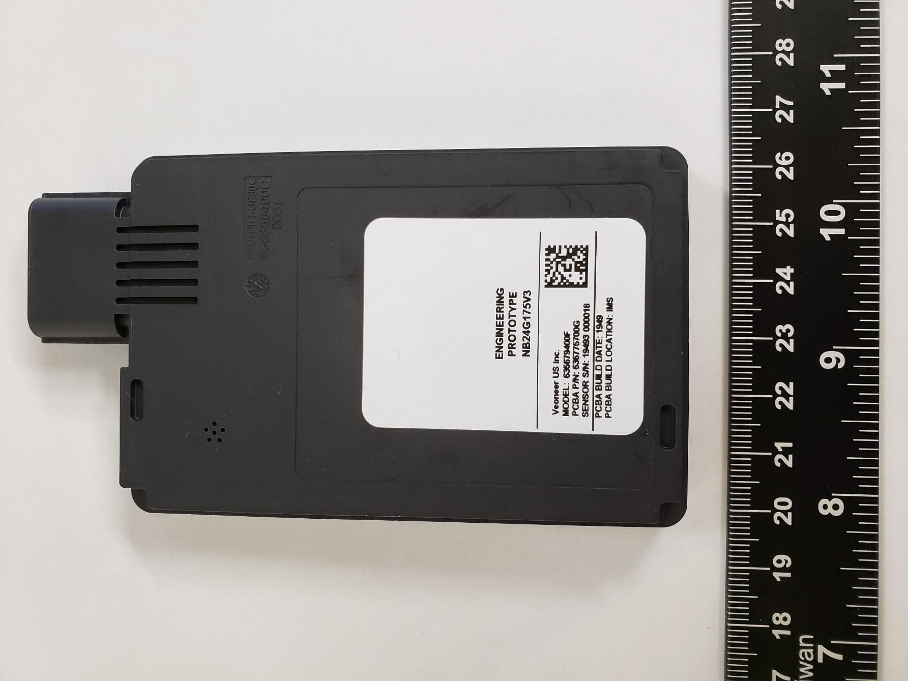
WU8NB24G175V3
May 28, 202024 GHz SRS Radar Sensor
Equipment Class
DXX - Part 15 Low Power Communication Device Transmitter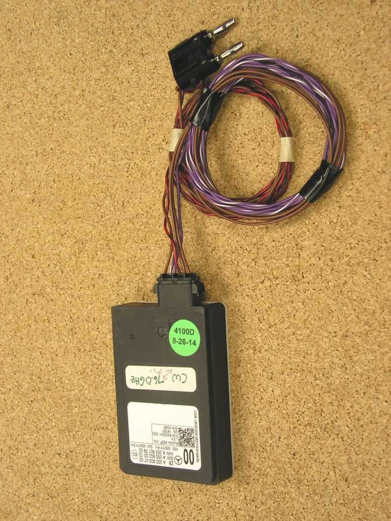
WU877MMRV1
May 25, 2015Vehicle Radar
Equipment Class
FDS - Part 15 Field Disturbance Sensor