WU8SQ2424 GHz UWB Radar Sensor SQ
Magna Electronics, LLC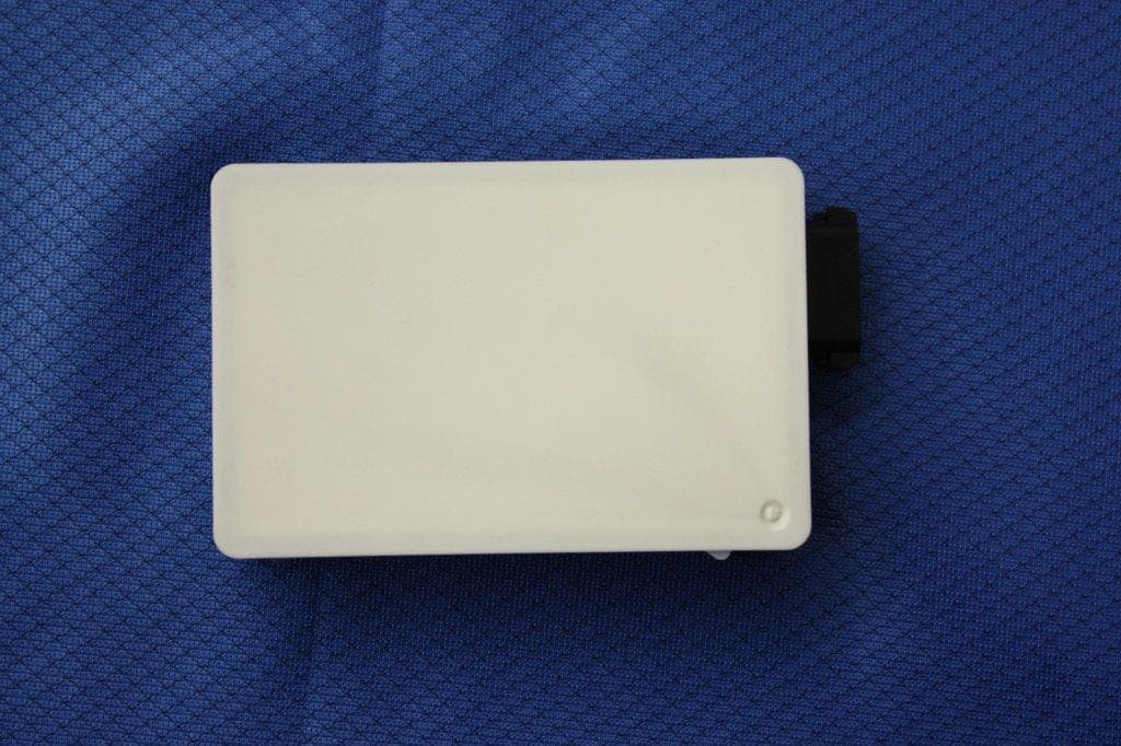
Click to zoom
Application Details
- Equipment Class
- UWB - Ultra Wideband Transmitter
- Date of Grant
- Oct 23, 2013
- Application Purpose
- Original Equipment
- Date of Application
- Sep 01, 2013
- Equipment Note
- 24 GHz UWB Radar Sensor SQ
- Frequency Range
- 24280.00000000 - 25652.00000000
- Company
- Magna Electronics, LLC
- Country
- United States
Documents & Files
Document Text
Text extracted from the exhibit documents filed with the FCC. Open a document above to read the original.
Users Manual
Copyright Autoliv Inc., All Rights Reserved Vervielfältigung oder Weitergabe ohne ausdrückliche, vorherige Genehmigung von Autoliv ist ausdrücklich verboten. Ver 1.0ger Technical Description & Installation Guide Model 24 SQ Sensor Version: 1.0 Date: 31. July 2013 File Name: 24 GHz SQ_Technical Description_Installation Guide Date: 31. July 2013 Autoliv Document, DUPLICATION or DISCLOSURE PROHIBITED without prior written consent 2 (9) Content CONTENT 2 1 GENERAL DESCRIPTION 3 1 SENSOR DESCRIPTION 4 1.1 SENSOR COMPONENTS 4 1.2 SENSOR DIMENSIONS 4 1.3 SENSING CHARACTERISTICS 5 2 RADAR WAVEFORM DESCRIPTION FOR MITIGATION 6 3 WAVEFORM TIMING DIAGRAM 7 4 VEHICLE INTEGRATION 8 5 REGULATORY HINTS 9 File Name: 24 GHz SQ_Technical Description_Installation Guide Date: 31. July 2013 Autoliv Document, DUPLICATION or DISCLOSURE PROHIBITED without prior written consent 3 (9) 1 General Description Autoliv manufactures different types of 24 GHz Short Range Radar sensors. The sensor types are working in two modes, NB (Narrowband) mode and UWB (Ultra Wide Band) mode. In the NB mode the sensor is working in the frequency band 24.25-24.25 GHz, in the UWB mode in the frequency band 24.25-26.65 GHz. The 24 GHz Short Range Radar platform is based on UWB technology using a proprietary frequency hopped, pulsed, coded FMCW like waveform. This advanced waveform enables very high resolution to be achieved in both range and Doppler. The fast signal processing allows very low latency and fast radar cycle times, a prerequisite for highly dynamic driving characteristics. The waveform is scalable in software. The sensors are used for automotive applications for both side looking and forward/back looking applications. Examples are warning and braking functions to improve the safety on the road. The 24 GHz radar platform covers variants which differ in their individual waveform and signal processing. Depending on the application (front or side or rear) the variants cover a specific detection range (short range or mid range) and detection zone. MRR (Mid Range Range): 0.2 – 65m ±8° detection zone SRR (Short Range Radar) Front: 0.2 – 30m ±40° detection zone SRR (Short Range Radar) Side: 0.2 – 10m ±40° detection zone MMR (Multi Mode Radar): 0.2 – 30m ±40° detection zone 0.2 – 65m ±8° detection zone SQ (Multi Mode Radar): 0.2 – 30m ±40° detection zone 0.2 – 65m ±8° detection zone MRR sensors are used for medium range applications such as forward collision warning. SRR sensors are used for short range applications such as Stop&Go or blind spot monitoring. MMR & SQ sensors have combined SRR and MRR functionality and are designed to function in both a short range and a longer range. The 24 GHz SQ sensor is an advanced development of the 24 GHz MMR sensor. The technical specification for the 24 GHz SQ sensor remain the same. File Name: 24 GHz SQ_Technical Description_Installation Guide Date: 31. July 2013 Autoliv Document, DUPLICATION or DISCLOSURE PROHIBITED without prior written consent 4 (9) 1 Sensor Description 1.1 Sensor Components The sensor consists of five main mechanical components (Housing, DSP Board, Shielding, RF Board, Radome). Sensor Components The connector header is part of the sensor plastic housing. Two connector options are possible. • 1x6 Hirschman (shown) • 1x8 USCAR 1.2 Sensor Dimensions The assembly process is in an advanced robot based production process. The size and light weight of approx.140 grams reduce the complexity of integration across a wide range of vehicle platforms. File Name: 24 GHz SQ_Technical Description_Installation Guide Date: 31. July 2013 Autoliv Document, DUPLICATION or DISCLOSURE PROHIBITED without prior written consent 5 (9) 1.3 Sensing Characteristics The specification for SRR (Short Range Radar) and MRR (Mid Range Radar) are different due to a different range of detection and field of view. The MMR (Multi Mode Radar) is a combination of SRR and MRR. The SQ sensor is an advanced version of the MMR sensor. 65m 30m Short Range Field of View SR FOV Mid Range Field of View MR FOV Detection Zone for SRR and MRR File Name: 24 GHz SQ_Technical Description_Installation Guide Date: 31. July 2013 Autoliv Document, DUPLICATION or DISCLOSURE PROHIBITED without prior written consent 6 (9) 2 Radar Waveform Description for Mitigation Autoliv has developed a proprietary frequency hopped, pulsed, coded FMCW like waveform. The radar codes transmit information in time and frequency and separates return information in both the doppler domain and distance domain. A target return can be separated from a target return of another transmitter station in three ways. 1. During the frequency dwell segment of the waveform (very short, approx. 6us) the waveform is transmitted with a coded pulse waveform. The receiver gate is only open for specific time slots. These two combine to reduce the effect of interfering "on frequency" transmitters. 2. The waveform sweeps over a very wide bandwidth in a short period of time (1GHz in 20ms). The IF bandwidth is very small (less than approx.. 1MHz) thus the rejection of interfering stations is very high as it is related to the ratio of the spread bandwidth and the IF bandwidth. 3. The transmit waveform is a random frequency hop (actually a coded frequency). Thus any interfering stations can be distinguished from the required transmitter as they do not transmit in the same coded frequency space. The randomness of the pulse waveform and the frequency hopping results in the overall effect that interferers are mitigated and are suppressed to behave as noise like signals in the receiver chain. This mitigates the deleterious effects on the signal processing chain. File Name: 24 GHz SQ_Technical Description_Installation Guide Date: 31. July 2013 Autoliv Document, DUPLICATION or DISCLOSURE PROHIBITED without prior written consent 7 (9) 3 Waveform Timing Diagram Freq. U W B N B Time/ms 2020 Frequency vs. Time Diagram Narrowband Emission UWB Emission File Name: 24 GHz SQ_Technical Descr…
Text truncated - open the document above for the full version.
ID Label/Location Info
202-LSB065 SQ
Test Report
Compliance Worldwide, Inc. - 357 Main Street - Sandown, NH 03873 (603) 887 3903 Fax 887 6445 http://www.complianceworldwide.com COMPLIANCE WORLDWIDE INC. TEST REPORT 388-13 In Accordance with the Requirements of Industry Canada RSS 220, Issue 1, March 2009 Federal Communications Commission 47 CFR Part 15, Part F Technical Requirements for Vehicular Radar Systems Issued to Autoliv Active Safety 1001 Pawtucket Blvd Lowell, MA 01854 978-674-6500 For the 24 GHz SQ Sensor Model Number: 24 GHz SQ FCC ID: WU8SQ24 IC: 8436B-SQ24 Report Issued on August 2, 2013 Tested By This test report shall not be reproduced, except in full, without written permission from Compliance Worldwide, Inc. Test Number: 388-13 Issue Date: 8/2/2013 Page 2 of 27 Compliance Worldwide, Inc. - 357 Main Street - Sandown, NH 03873 (603) 887 3903 Fax 887 6445 http://www.cw-inc.com Table of Contents 1. Scope .................................................................................................................................. 3 2. Product Details.................................................................................................................... 3 2.1. Manufacturer ..............................................................................................................3 2.2. Model Number............................................................................................................ 3 2.3. Serial Number ............................................................................................................ 3 2.4. Description ................................................................................................................. 3 2.5. Power Source............................................................................................................. 3 2.6. Hardware Revision ..................................................................................................... 3 2.7. Software Revision ...................................................................................................... 3 2.8. Modulation Type......................................................................................................... 3 2.9. Operating Frequency ................................................................................................. 3 2.10. EMC Modifications ................................................................................................... 3 3. Product Configuration ......................................................................................................... 3 3.1. Operational Characteristics & Software ..................................................................... 3 3.2. EUT Hardware ........................................................................................................... 4 3.3. EUT Cables/Transducers ........................................................................................... 4 3.4. Support Equipment .................................................................................................... 4 3.5. Test Setup Diagram ................................................................................................... 5 4. Measurements Parameters................................................................................................. 6 4.1. Measurement Equipment Used to Perform Test ........................................................ 6 4.2. Measurement & Equipment Setup ............................................................................. 7 4.3. Measurement Procedure............................................................................................ 7 4.4. Measurement Uncertainty .......................................................................................... 7 5. Measurement Summary...................................................................................................... 8 6. Measurement Data.............................................................................................................. 9 6.1. Antenna Requirement ................................................................................................ 9 6.2. Operational Requirements ......................................................................................... 9 6.3. UWB Bandwidth ....................................................................................................... 10 6.4. Emissions Attenuation above the Horizontal Plane.................................................. 13 6.5. Spurious Radiated Emissions .................................................................................. 14 6.6. Peak Emissions in a 50 MHz Bandwidth.................................................................. 21 6.7. Devices that Employ Gated Transmissions ............................................................. 22 6.8. Effect of Voltage Variations on Peak Emissions ...................................................... 22 6.9. Frequency Stability of Unmodulated Carrier...................................................23 6.10. Public Exposure to Radio Frequency Energy Levels ............................................. 24 7. Test Images ...................................................................................................................... 25 7.1. Spurious and Harmonic Emissions - 1 to 18 GHz .................................................... 25 7.2. Spurious and Harmonic Emissions - 18 to 40 GHz .................................................. 26 8. Test Site Description ......................................................................................................... 27 Test Number: 388-13 Issue Date: 8/2/2013 Page 3 of 27 Compliance Worldwide, Inc. - 357 Main Street - Sandown, NH 03873 (603) 887 3903 Fax 887 6445 http://www.cw-inc.com 1. Scope This test report certifies that the Autoliv Active Safety 24 GHz SQ Sensor, as tested, meets the FCC Part 15, Subpart F and Industry Canada RSS 220 requirements. The s…
Text truncated - open the document above for the full version.
Test Setup Photos
Test Number: 388-13 Issue Date: 8/2/2013 Page 25 of 27 Compliance Worldwide, Inc. - 357 Main Street - Sandown, NH 03873 (603) 887 3903 Fax 887 6445 http://www.cw-inc.com 7. Test Images 7.1. Spurious and Harmonic Emissions – 1 to 18 GHz Test Number: 388-13 Issue Date: 8/2/2013 Page 26 of 27 Compliance Worldwide, Inc. - 357 Main Street - Sandown, NH 03873 (603) 887 3903 Fax 887 6445 http://www.cw-inc.com 7. Test Images 7.2. Spurious and Harmonic Emissions – 18 to 40 GHz
Contact Information
Applicant
Kim Mooney(Director, Radar Platforms)
Technical Contact
Test Firm
Compliance Worldwide, Inc.Deb Bourbeau
Technical Specifications
| # | Rule Parts | Frequency Range | Power Output |
|---|---|---|---|
| 1 | 15F | 24.28 GHz - 25.65 GHz | - |
Other Applications from Magna Electronics, LLC
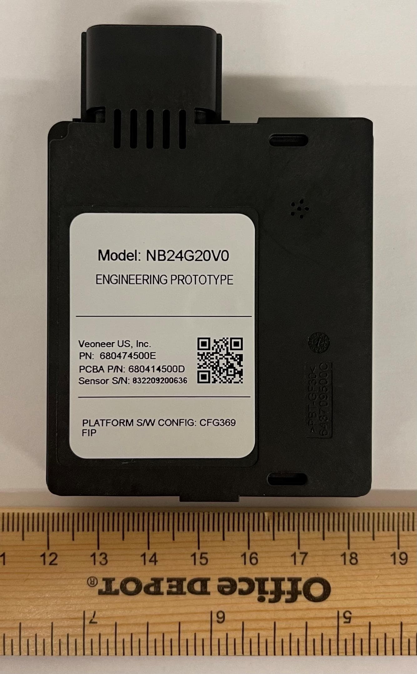
WU8NB24G20V0
May 18, 202124 GHz NB automotive radar
Equipment Class
DXX - Part 15 Low Power Communication Device Transmitter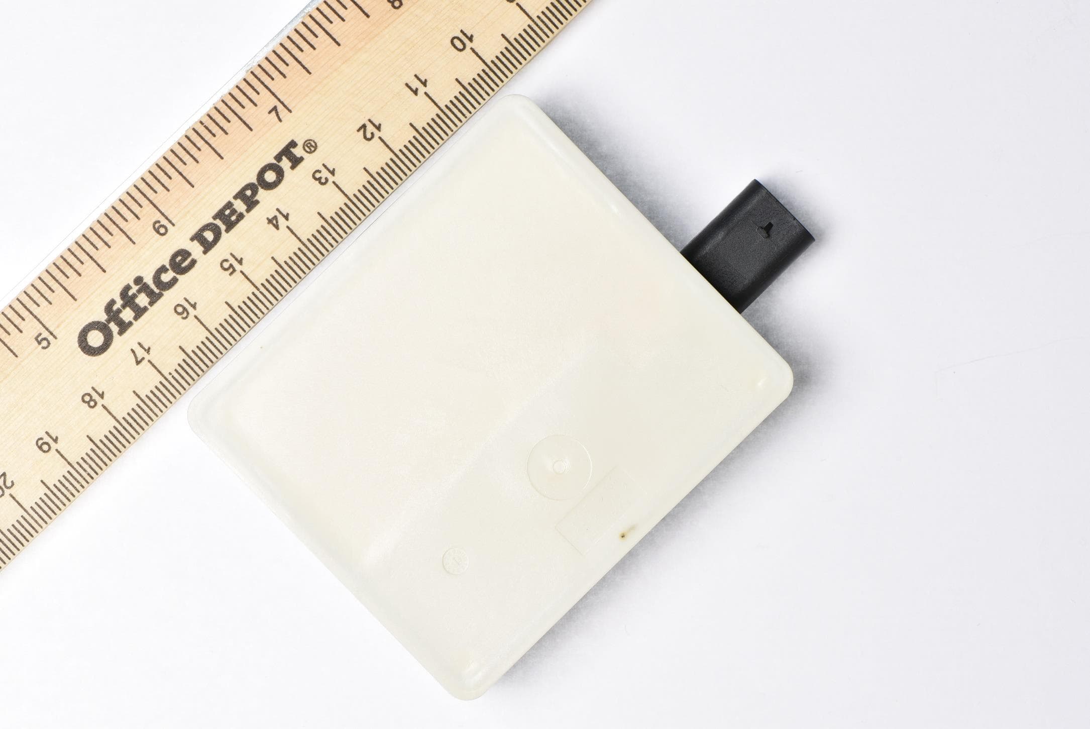
WU877V125CRN
Apr 28, 202177 GHz CRN Radar Sensor
Equipment Class
VRD - Part 95 Vehicular Radar Systems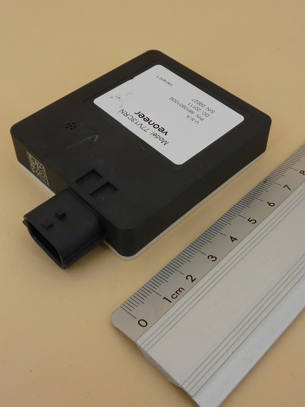
WU877V13CRN
Aug 24, 2020CRN Radar Sensor
Equipment Class
VRD - Part 95 Vehicular Radar Systems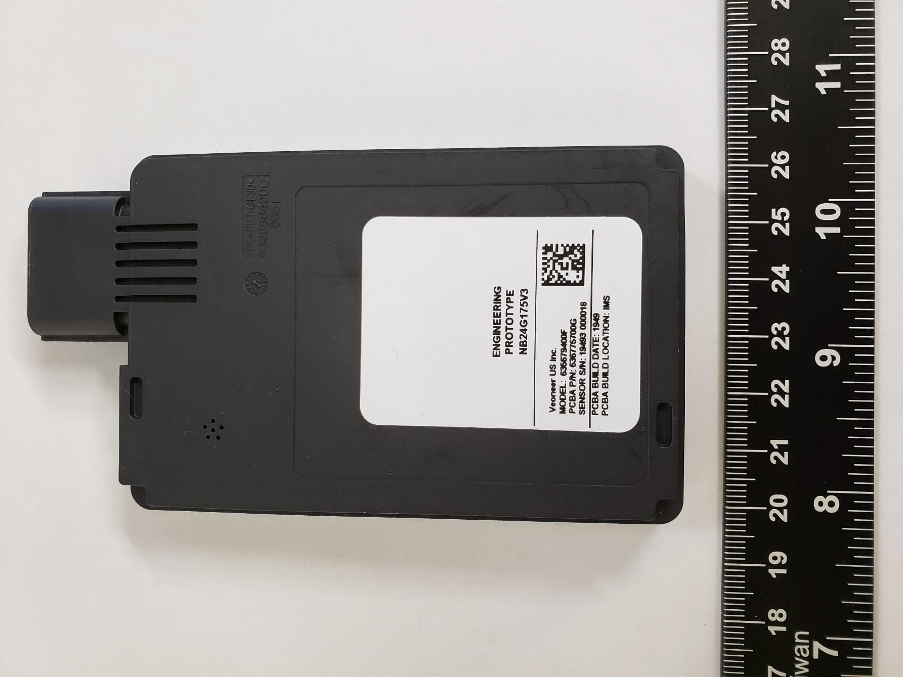
WU8NB24G175V3
May 28, 202024 GHz SRS Radar Sensor
Equipment Class
DXX - Part 15 Low Power Communication Device Transmitter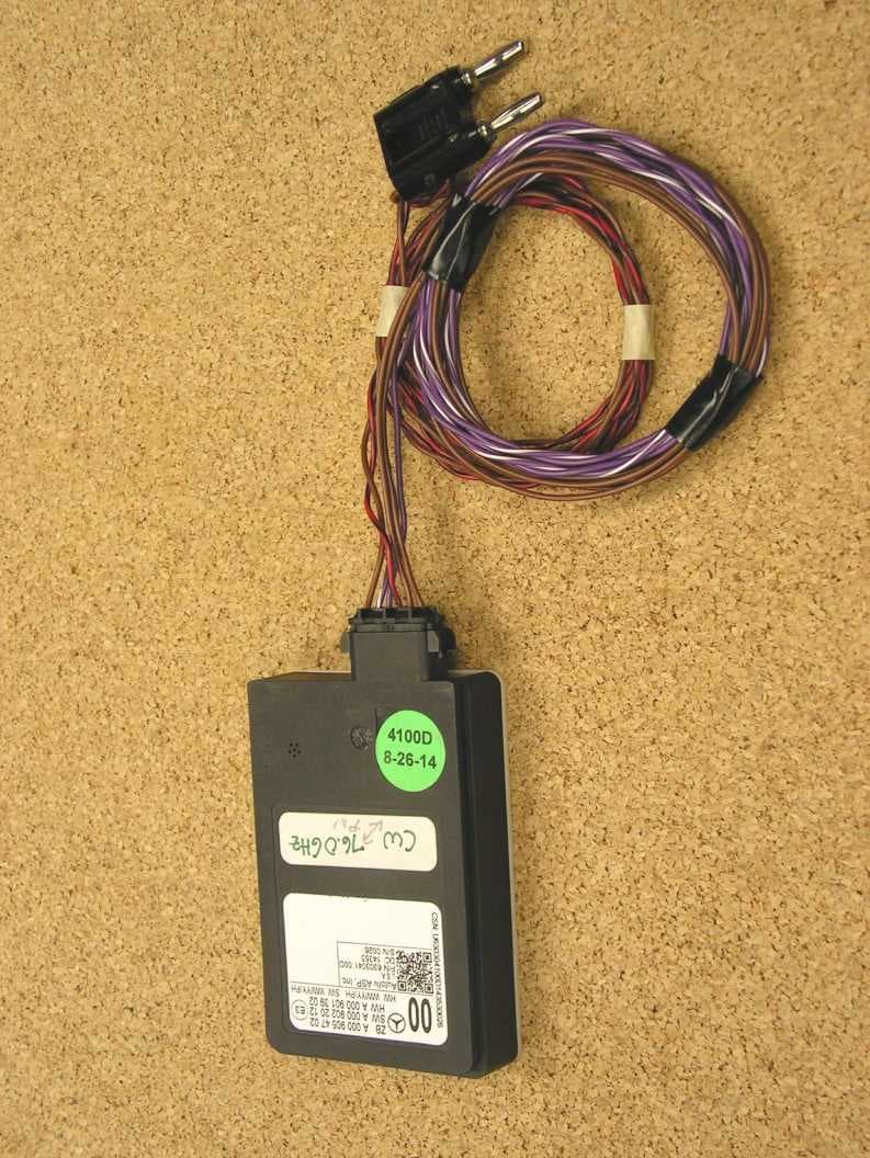
WU877MMRV1
May 25, 2015Vehicle Radar
Equipment Class
FDS - Part 15 Field Disturbance Sensor