WU8SRSC524 GHz Ultra Wideband Sensor C5
Magna Electronics, LLC
Click to zoom
Application Details
- Equipment Class
- UWB - Ultra Wideband Transmitter
- Date of Grant
- Nov 19, 2009
- Application Purpose
- Original Equipment
- Date of Application
- Sep 21, 2009
- Equipment Note
- 24 GHz Ultra Wideband Sensor C5
- Frequency Range
- 23575.00000000 - 25258.00000000
- Company
- Magna Electronics, LLC
- Country
- United States
Documents & Files
Document Text
Text extracted from the exhibit documents filed with the FCC. Open a document above to read the original.
Operational Description
REVISION HISTORY Rev Description Date Apprv’d 000 Initial Release per ECO 066734 Ref. PLM TITLE: Installation Specification, Radar Sensor DOCUMENT NO: E567781 INSTALLATION SPECIFICATION REV. 000, PAGE 1 OF 14 AEL, Inc. 1011B Pawtucket Blvd. Lowell, MA 01853 ATTENTION USER OF THIS DOCUMENT IS RESPONSIBLE FOR DETERMINING CURRENT REVISION LEVEL BEFORE USING DOCUMENT. ©AUTOLIV INC. THIS DOCUMENT AND THE DATA DISCLOSED HEREIN OR HEREWITH IS PROPRIETARY AND MAY NOT BE REPRODUCED, USED OR DISCLOSED IN WHOLE OR IN PART WITHOUT WRITTEN PERMISSION FROM AUTOLIV INC. Title: Installation Specifications, Radar Sensors Doc. No. E567781 INSTALLATION SPECIFICATION Rev. 000, Page 2 of 14 TABLE OF CONTENTS 1.0 PURPOSE/SCOPE 3 2.0 MATERIALS/EQUIPMENT 3 3.0 APPLICABLE DOCUMENTS 3 4.0 DEFINITIONS 3 5.0 SPECIFICATIONS 3 5.1. Preface 3 5.2. SLR Sensor 3 5.2.1. Dimensions and Weight of the SLR Sensor 3 5.0 SPECIFICATIONS 4 5.2.2 Detection Range / Azimuth Angle Measurement Range 5 5.2.3 Detection Angle Elevation 6 5.3.1 Distance To The Bumper Material 7 5.3.2 Angle with respect to bumper material 7 5.3.3 Effect Of Type- And Thickness Of Fascia Material 8 5.3.4 Effect of the paint 8 5.3.5 Smoothness of Fascia in Front of Antenna 8 5.3.6 Environmental Conditions 9 5.3.7 Protection From Mud And Dirt Buildup 10 5.3.8 Sensor mounting thermal considerations 10 6.0 SLR SENSOR SYSTEM 11 6.1. Coordinate System 11 6.2. Numbering of the Sensors 12 6.3. Installation Dimensions 13 6.3.1 Y-direction 13 6.3.2 X-direction 13 6.3.3 Azimuth angle 13 6.3.4 Elevation Angle 13 7.0 APPENDIX 14 7.1. Range Performance vs Attenuation 14 LIST OF FIGURES Figure 1 4 Figure 2 5 Figure 3 6 Figure 4 6 Figure 5 7 Figure 6 7 Figure 7 10 Figure 8 11 Figure 9 12 Figure 10 12 Figure 11 14 Title: Installation Specifications, Radar Sensors Doc. No. E567781 INSTALLATION SPECIFICATION Rev. 000, Page 3 of 14 1.0 PURPOSE/SCOPE This document describes the specifications for installation of type SLR Radar Sensors. 2.0 MATERIALS/EQUIPMENT N/A 3.0 APPLICABLE DOCUMENTS Outline 6181175 DIN 40050-9 IP6K9K IEC 68-2-6 Fc IEC 68-2-7 IEC68-2-10 IEC68-2-11 Ka IEC 668-2-14Nb IEC 68-2-27 IEC 68-2-29 IEC68-2-30 IEC68-2-32 IEC68-2-38 IEC68-2-50 IEC68-2-51 IEC68-2-52 IEC68-2-56 IEC68-2-64Fh IEC529, 13.4 SAE J1211 SAE J1812 SAE J1879 4.0 DEFINITIONS N/A 5.0 SPECIFICATIONS 5.1. Preface This chapter describes the specifications to install short range SLR radar into bumpers. These specifications shall be complied with to enable the specified characteristics of the sensors as well as the complete system. Due to the various installation situations and applications, a measurement check is required to verify the actual installation implementation. 5.2. SLR Sensor This chapter describes the characteristics relevant to the installation of SLR sensors in the bumper. In addition general specifications are mentioned, which have to be followed for each position to enable sufficient sensor performance. Therefore the following guidelines are to be observed very carefully. See annex for performance measurements. 5.2.1. Dimensions and Weight of the SLR Sensor Figure 1 shows the dimensions of the SLR sensor (C-sample status) and details the mounting of the sensor. Please refer to “Outline 6181175” for detailed drawings. Sensor weight: 190 grams max. Title: Installation Specifications, Radar Sensors Doc. No. E567781 INSTALLATION SPECIFICATION Rev. 000, Page 4 of 14 5.0 SPECIFICATIONS Figure 1 Important note: The two mounting holes are not specified for m ounting the complete sensor. They do not provide the mechanical properties to keep the sensor in place. They shall be used to fix the sensor in a mounting bracket. Mounting tabs are to be fa stened tight to mounting bracket using appropriate fastener. Maximum strength per tab is 270 N. Title: Installation Specifications, Radar Sensors Doc. No. E567781 INSTALLATION SPECIFICATION Rev. 000, Page 5 of 14 5.0 SPECIFICATIONS 5.2 SLR Sensor (cont’d) 5.2.2 Detection Range / Azimuth Angle Measurement Range Figure 2 displays the detection area of the SLR sensor. One should differentiate between the detection area of the sensor and the angle measurement area. The angle measurement area is reduced to ±40° around bore sight whereas the detection area is ±65°. The detection area is related to the 10dB points, this means the area where the signal amplitude is reduced by 10dB compared to bore sight direction. Within the detection area of the antennas there must not be metal parts like screws, mounting brackets, license plate etc. The impact reducing foam material, clips or fascia laminations has to be avoided in that area. Figure 2 Title: Installation Specifications, Radar Sensors Doc. No. E567781 INSTALLATION SPECIFICATION Rev. 000, Page 6 of 14 5.0 SPECIFICATIONS 5.2 SLR Sensor (cont’d) 5.2.3 Detection Angle Elevation Figure 3 shows the detection area of the antennas in elevation. The detection area of ±8 ° is related to the 3dB points, this means the area where the signal amplitude is reduced by 3dB compared to bore sight direction. To avoid close range false objects there must not be metal parts like screws, mounting brackets, license plate etc in an angle of ±30 ° (see figure 3). Impact reducing foam material, clips or fascia laminations must be avoided in this area. Figure 4 shows details of objects keep out zone. Figure 3 Figure 4 Title: Installation Specifications, Radar Sensors Doc. No. E567781 INSTALLATION SPECIFICATION Rev. 000, Page 7 of 14 5.0 SPECIFICATIONS 5.3 Installation Specifications For Individual Sensors 5.3.1 Distance To The Bumper Material The distance of the SLR sensor to the bumper shall be between 5 and 20 mm. If the distance is below 5 mm a significant signal loss occurs. If the distance is larger, error ranges may appear within the close range. Figure 5 5.3.2 Angle with respect to bumper material The angle φ of the sensor with regard to the bumper should be 0 ° , meaning the sensor should be installed parallel to the bumper. If …
Text truncated - open the document above for the full version.
Test Report
Compliance Worldwide, Inc. - 357 Main Street - Sandown, NH 03873 COMPLIANCE WORLDWIDE INC. TEST REPORT 287-09R1 In Accordance with the Requirements of Industry Canada RSS 220, Issue 1, March 2009 Federal Communications Commission 47 CFR Part 15, Part F Technical Requirements for Vehicular Radar Systems Issued to Autoliv Electronics 1011B Pawtucket Blvd PO Box 1858 Lowell, MA 01853 Tel: 978-674-6500 For the 24 GHz SRS Sensor FCC ID: WU8SRSC5 IC: 8436B-6181175 Report Issued on August 27, 2009 This test report shall not be reproduced, except in full, without written permission from Compliance Worldwide, Inc. (603) 887 3903 Fax 887 6445 http://www.complianceworldwide.com Test Number: 287-09R1 Issue Date: 08/27/2009 Page 2 of 31 Compliance Worldwide, Inc. - 357 Main Street - Sandown, NH 03873 (603) 887 3903 Fax 887 6445 http://www.cw-inc.com Table of Contents 1. Scope .................................................................................................................................. 3 2. Product Details.................................................................................................................... 3 2.1. Manufacturer ..............................................................................................................3 2.2. Model Number............................................................................................................ 3 2.3. Serial Number ............................................................................................................ 3 2.4. Description ................................................................................................................. 3 2.5. Power Source............................................................................................................. 3 2.6. Hardware Revision ..................................................................................................... 3 2.7. Software Revision ...................................................................................................... 3 2.8. Modulation Type......................................................................................................... 3 2.9. Operating Frequency ................................................................................................. 3 2.10. EMC Modifications ................................................................................................... 3 3. Product Configuration ......................................................................................................... 3 3.1. Operational Characteristics & Software ..................................................................... 3 3.2. EUT Hardware ........................................................................................................... 4 3.3. EUT Cables/Transducers ........................................................................................... 4 3.4. Support Equipment .................................................................................................... 4 3.5. Test Setup Diagram ................................................................................................... 5 4. Measurements Parameters................................................................................................. 6 4.1. Measurement Equipment Used to Perform Test ........................................................ 6 4.2. Measurement & Equipment Setup ............................................................................. 7 4.3. Measurement Procedure............................................................................................ 7 4.4. Measurement Uncertainty .......................................................................................... 7 5. Measurement Summary...................................................................................................... 8 6. Measurement Data.............................................................................................................. 9 6.1. Radiated Field Strength of Fundamental ................................................................... 9 6.2. Radiated Field Strength of Harmonics ....................................................................... 9 6.3. UWB Bandwidth ......................................................................................................... 9 6.4. Emissions Attenuation above the Horizontal Plane.................................................. 13 6.5. Spurious Radiated Emissions .................................................................................. 21 6.6. Peak Emissions in a 50 MHz Bandwidth.................................................................. 25 6.7. Devices that Employ Gated Transmissions ............................................................. 27 6.8. Effect of Voltage Variations on Peak Emissions ...................................................... 27 6.9. Frequency Stability of Unmodulated Carrier...................................................28 6.10. Public Exposure to Radio Frequency Energy Levels ............................................. 28 7. Test Images ...................................................................................................................... 29 7.1. Spurious and Harmonic Emissions - Front............................................................... 30 7.2. Spurious and Harmonic Emissions - Rear ............................................................... 31 8. Test Site Description ......................................................................................................... 32 Test Number: 287-09R1 Issue Date: 08/27/2009 Page 3 of 31 Compliance Worldwide, Inc. - 357 Main Street - Sandown, NH 03873 (603) 887 3903 Fax 887 6445 http://www.cw-inc.com 1. Scope This test report certifies that the Autoliv Electronics 24 GHz SRS Sensor, New Design, as tested, meets the FCC Part 15, Subpart F and Industry Canada RSS 220 requirements. Th…
Text truncated - open the document above for the full version.
Contact Information
Applicant
Kim Mooney(Director, Radar Platforms)
Technical Contact
Test Firm
Compliance Worldwide, Inc.Deb Bourbeau
Technical Specifications
| # | Rule Parts | Frequency Range | Power Output |
|---|---|---|---|
| 2 | 15F | 23.57 GHz - 25.26 GHz | - |
Other Applications from Magna Electronics, LLC
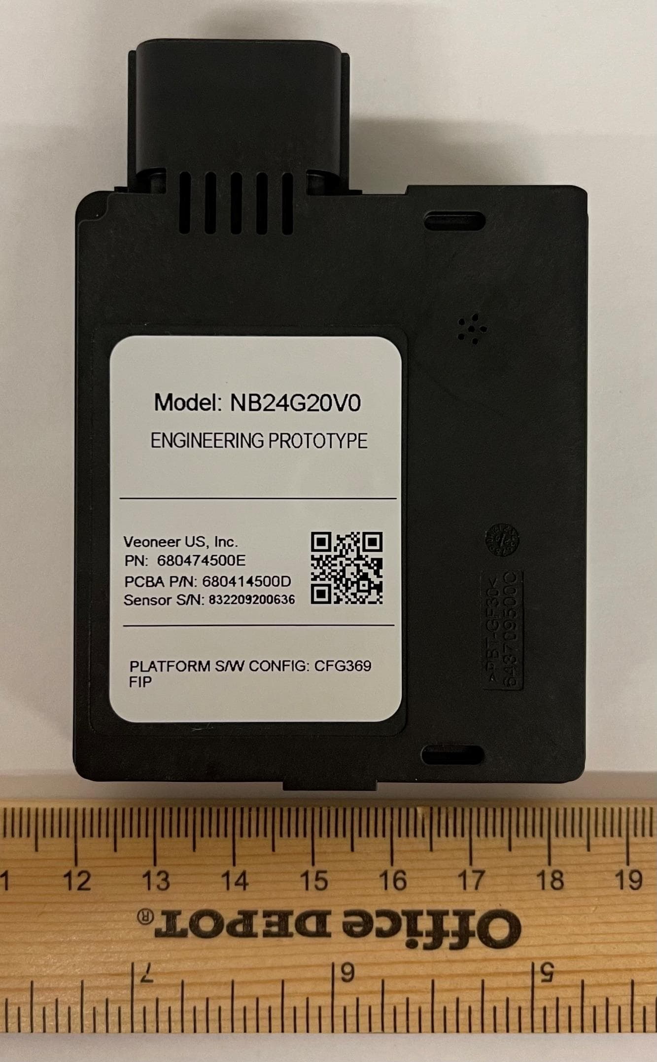
WU8NB24G20V0
May 18, 202124 GHz NB automotive radar
Equipment Class
DXX - Part 15 Low Power Communication Device Transmitter
WU877V125CRN
Apr 28, 202177 GHz CRN Radar Sensor
Equipment Class
VRD - Part 95 Vehicular Radar Systems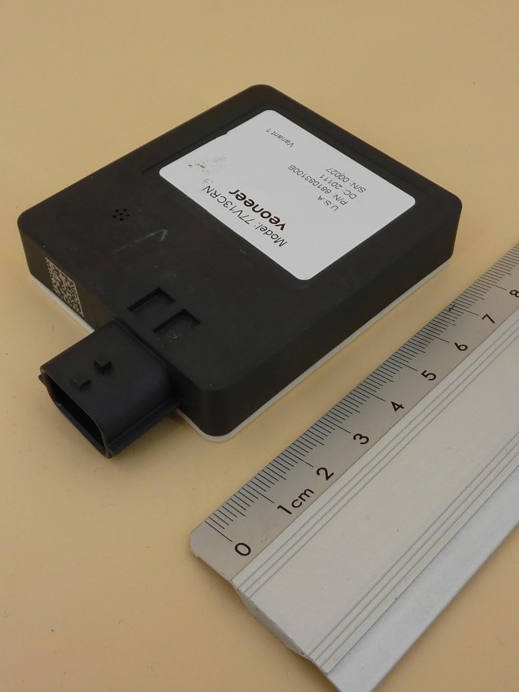
WU877V13CRN
Aug 24, 2020CRN Radar Sensor
Equipment Class
VRD - Part 95 Vehicular Radar Systems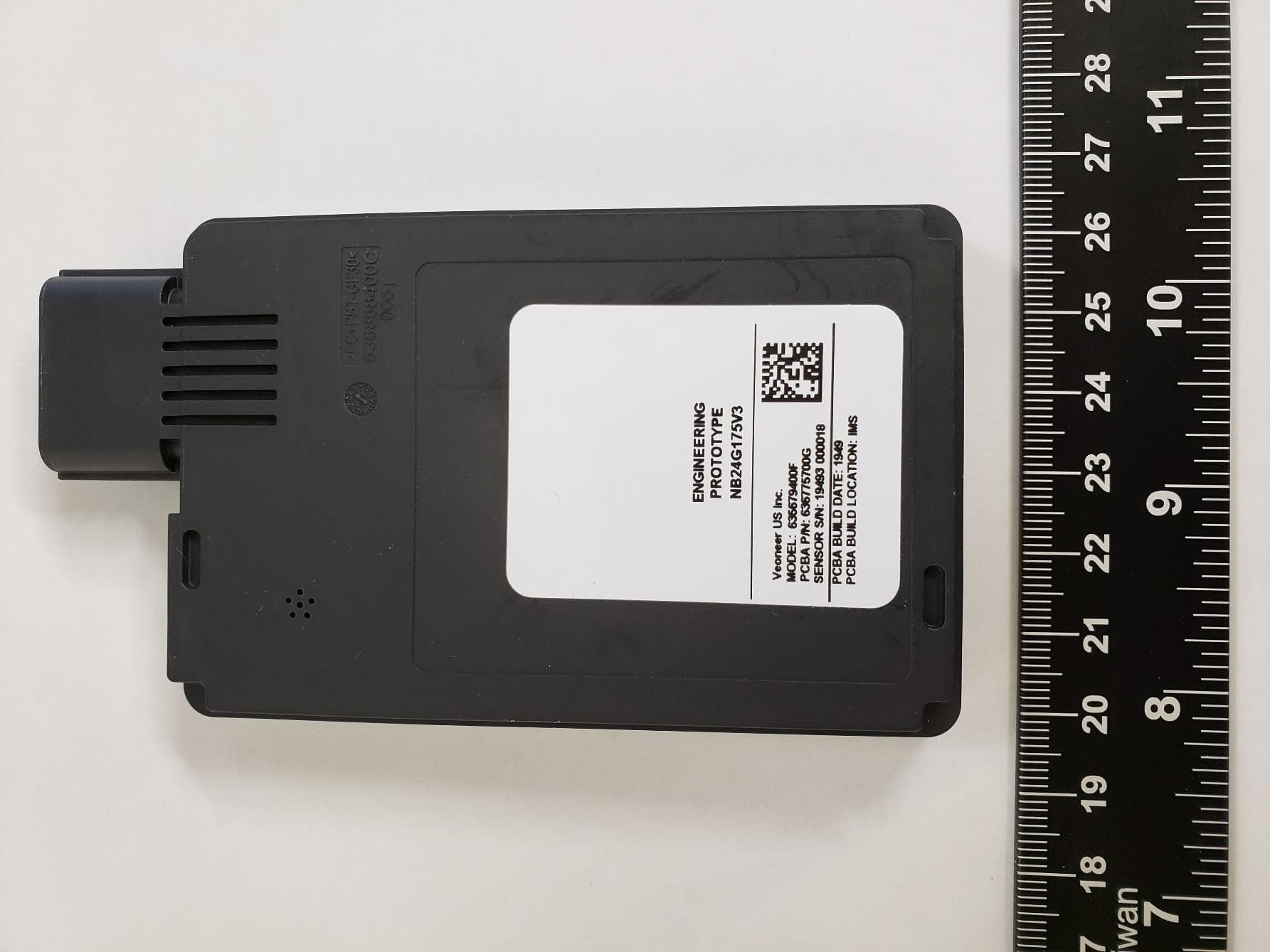
WU8NB24G175V3
May 28, 202024 GHz SRS Radar Sensor
Equipment Class
DXX - Part 15 Low Power Communication Device Transmitter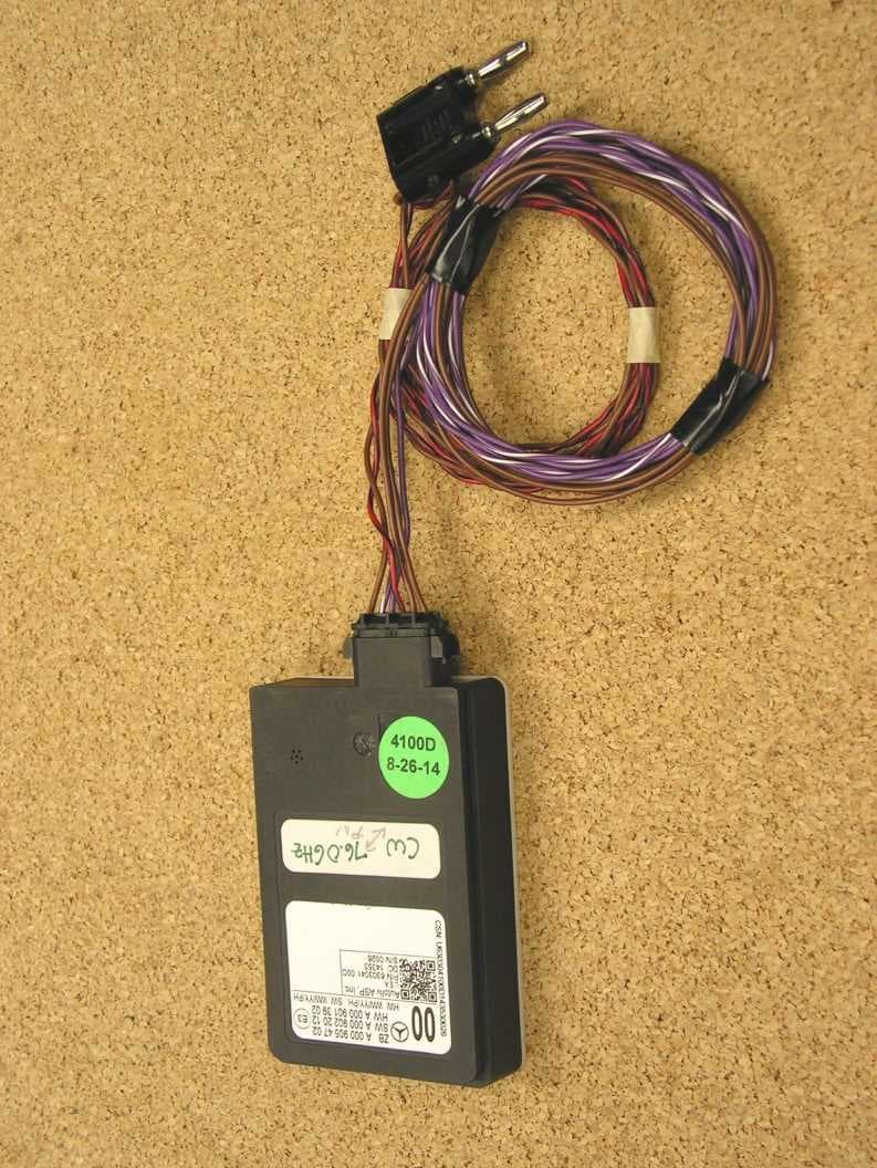
WU877MMRV1
May 25, 2015Vehicle Radar
Equipment Class
FDS - Part 15 Field Disturbance Sensor