WZ4010A0001RFID PORTAL READER
JADAK, a business unit of Novanta Corporation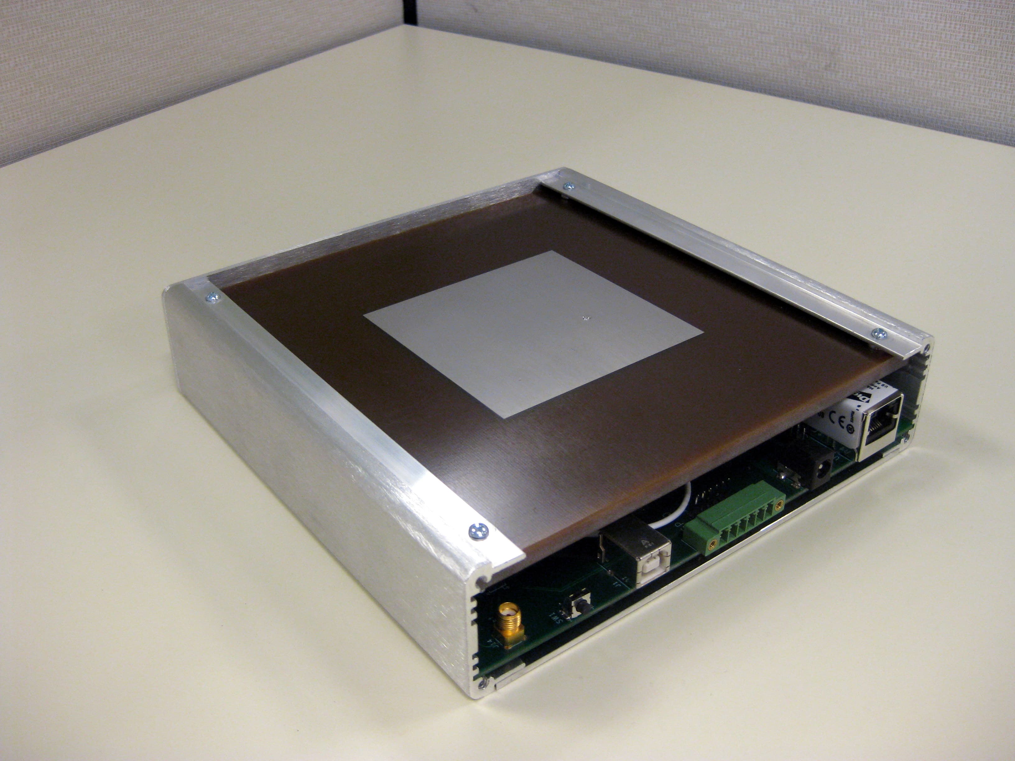
Click to zoom
Application Details
- Equipment Class
- DSS - Part 15 Spread Spectrum Transmitter
- Date of Grant
- Apr 20, 2010
- Application Purpose
- Original Equipment
- Date of Application
- Apr 20, 2010
- Equipment Note
- RFID PORTAL READER
- Frequency Range
- 902.30000000 - 927.70000000
- Country
- United States
Documents & Files
Document Text
Text extracted from the exhibit documents filed with the FCC. Open a document above to read the original.
Users Manual
SR100 USER GUIDE VERSION 1.0 SR100 User Guide Page | 2 CONTACT INFORMATION SKYETEK, INC. 1525 Market St. Suite 200 Denver, CO 80202 http://www.skyetek.com SALES: [email protected] TECHNICAL SUPPORT: [email protected] http://support.skyetek.com SR100 User Guide Page | 3 TA B L E O F C O N T E N T S SR100 User Guide ............................................................................................ 1 Contact Information ......................................................................................... 2 Table of Contents ............................................................................................ 3 Chapter 1 ...................................................................................................... 6 SR100 Overview ........................................................................................... 6 Features.................................................................................................. 6 SkyeReader Console .................................................................................... 6 FCC Notice ............................................................................................... 6 Note Regarding RF Exposure .......................................................................... 6 Chapter 2 ...................................................................................................... 8 Mechanical Specifications ............................................................................... 8 Chapter 3 ...................................................................................................... 9 Environment Specifications .............................................................................. 9 General Ratings and Operating Conditions ......................................................... 9 Chapter 4 ..................................................................................................... 10 Electrical Specifications ................................................................................ 10 Absolute Maximum Ratings .......................................................................... 10 Chapter 5 ..................................................................................................... 11 Radio Specifications and Regional Compliance ...................................................... 11 RF Radio Power ........................................................................................ 11 Frequency Range ...................................................................................... 11 Tag Protocols ........................................................................................... 11 Regional Regulations .................................................................................. 11 Radio Specifications................................................................................... 11 Chapter 6 ..................................................................................................... 13 Host Interface Specification ............................................................................ 13 SR100 User Guide Page | 4 USB ...................................................................................................... 13 TCP/IP ................................................................................................... 13 Discovery ........................................................................................................ 13 Opening a socket ............................................................................................... 14 Chapter 7 ..................................................................................................... 15 Antenna Options .......................................................................................... 15 Internal Antenna ....................................................................................... 15 External Antenna ...................................................................................... 15 Chapter 8 ..................................................................................................... 16 Software Specifications ................................................................................. 16 Host Communication – SkyeTek Protocol v3 ...................................................... 16 SkyeReader Console Software ....................................................................... 17 Chapter 9 ..................................................................................................... 18 System Parameters ...................................................................................... 18 Changing System Paramters ......................................................................... 18 System Parameter Descriptions ..................................................................... 18 Serial Number .................................................................................................. 19 Firmware Version .............................................................................................. 19 Hardware Version .............................................................................................. 19 Product Code ................................................................................................... 19 Reader ID ........................................................................................................ 20 Reader Name ................................................................................................... 20 User Port Direction ............................................................................................ 20 User Port Value ................................................................................................. 20 MUX Control ..................................................................................................... 21 Operating Mode ..................…
Text truncated - open the document above for the full version.
Operational Description
SR100 Operational description a) An operational description (relating to the block diagram) of all circuitry and devices provided for determining and stabilizing frequency, for suppression of spurious radiation, for limiting modulation, and for limiting power. Circuitry and devices for determining frequency • The Synthesizer is an Fractional N PLL which is used to scale the reference clock from 13 MHz to the operating frequency between 860 MHz to 960 MHz. • A TCXO reference provides the base frequency for the synthesizer. Circuitry and devices for stabilizing frequency • Attenuator pads on the output to increase reverse isolation and reduce pulling on the synthesizer. • RF Shields to prevent radiated RF to couple back on the synthesizer circuitry and cause frequency instability or pulling. • Matching circuitry on the output to decrease frequency instability due to mismatch between the synthesizer stage and the succeeding stages. Circuitry and devices for suppression of spurious radiation • Shields for suppression of spurious radiation due to power amplification. • Low pass filter before the antenna port to suppression harmonics (especially the second harmonic) of the fundamental carrier frequency. Circuitry and devices for limiting modulation and power • Power detector, internal DAC, directional coupler, digital attenuator and a closed loop power control scheme implemented in the microcontroller limits both modulation depth and power to user specified values with an accuracy of +‐1dB for a maximum power output of 30dBm (1 Watt). b) Describe the modulation scheme; including the type of modulation, and a description of the modulating signal (e.g. video, audio, or data). If applicable, include the maximum data rate, modulation index, and maximum transmit time during any 100 mS period. Make reference to any applicable interoperability standards or communication protocols. Description of modulation scheme Transmit modulation on the SkyeModule M10 Rev. G is dependent on the Tag protocol supported and used on the device. The M10 Rev. G natively supports the following Tag protocols 1. EPC Class1 Gen2 / ISO 180006C 2. ISO 180006B 3. EM4122 and EM 4123 The maximum transmit time in a 100ms period, modulation depth and data rate are a factor of the protocol under consideration. The type of modulation and description can similarly be found on the respective protocol standards. c) If the device is a Part 15.247 frequency hopping transmitter, describe compliance of the associated receiver with 15.247(a)(1) of the FCC rules (see attachment). Specifically, explain how the receiver’s input bandwidth matches the hopping channel bandwidth of the corresponding transmitter and how the receiver shifts frequencies in synchronization with the transmitted signal. Compliance with 15.247(a)(1) The SkyeModule M10 Rev. G is a frequency hopping transmitter and therefore complies with the receiver specifications laid out in the Part 15.247(a)(1). The input bandwidth of the receiver is filtered to match the hopping channel frequency of the transmitter and tracks the frequency of the transmitter because of its zero IF architecture thus maintaining synchronization at all times during operation. d) If the device is a Part 15.247 frequency‐hopping transmitter, describe how the device meets the definition of a frequency‐hopping spread spectrum system found in Section 2.1. The description should include the number of hopping frequencies, the time of occupancy (dwell time) per hopping channel and an explanation of how the hopping sequence is generated (provide an example of the hopping channel sequence). Also include a description of how each of the EUT’s hopping channels is used equally on average. Compliance with Frequency hopping spread spectrum The SkyeModule M10 Rev. G is a frequency hopping spread spectrum systems since it changes its frequency of operation at a predetermined rate and at specific frequencies. The M10 hops with nominal channel spacing of 200 KHz and at a minimum of 50 channels between 902 and 928 MHz. The M10 dwells at a channel for no more than 100 ms which is ensured with a timer driven interrupt on the microcontroller. The hopping channels are chosen pseudo randomly using a pseudo random function within the microcontroller which takes as its seed a random value (the system timer register value before commencement of hopping). The normal probability distribution of the pseudo random number ensures equal number of utilization of every channel over a sufficient time interval. Example for hopping 50 times among 50 channels between 902 – 928 MHz (channel spacing = 200 KHz) Hopping Sequence Hopping Channel 1 913 2 916.4 3 918.8 4 916.2 5 913.6 6 918.4 7 916 8 918.6 9 912.4 10 914 11 911 12 918 13 917.2 14 915.4 15 919.8 16 920 17 917.4 18 910.2 19 915.2 20 919.4 21 911.8 22 915.8 23 911.2 24 910.8 25 913.8 26 914.2 27 911.6 28 912.2 29 918.2 30 912 31 919.2 32 912.6 33 913.4 34 911.4 35 910.4 36 919.6 37 912.8 38 917 39 917.8 40 915 41 916.6 42 914.4 43 914.6 44 919 45 917.6 46 913.2 47 916.8 48 915.6 49 910.6 50 914.8 e) If the device is a Part 15.247 frequency‐hopping transmitter, describe how the EUT does not have the ability to coordinate with other FHSS systems in an effort to avoid the simultaneous occupancy of individual hopping frequencies by multiple transmitters. M10’s inability to coordinate with other FHSS systems Through firmware design in compliance with the requirement for the product
Operational Description
CIRCULAR POLARZIED RFID ANTENNA SR900RCP The SkyeTek SR900RCP antenna is a high performance, high efficiency RFID antenna designed to work with the SkyeTek SR100. It features a rugged aluminum case with ABS plastic radome, which houses a Right Hand Circularly Polarized antenna for use in the 902‐928MHz spectrum. The antenna has excellent VSWR across the band and small axial ratio to maximize performance with any tag orientation. The antenna is offered with a bulkhead SMA connector. Specification Part Number SR900RCP Operating Frequency 902‐928 MHz Gain 5.35 dBi 2:1 VSWR Bandwidth 40MHz Front to back ratio 37.77 Polarization RHCP Axial ratio 0.14 dB Size 7” x 7” Operating Temperature ‐25° to 70°C
RF Exposure Info
Prediction of MPE limit at a given distance Equation from page 18 of OET Bulletin 65, Edition 97-01 where:S = power density P = power input to the antenna G = power gain of the antenna in the direction of interest relative to an isotropic radiator R = distance to the center of radiation of the antenna Maximum peak output power at antenna input terminal:30.00(dBm) Maximum peak output power at antenna input terminal:1000(mW) Antenna gain(maximum):5.35(dBi) Maximum antenna gain:3.427677865(numeric) Time Averaging:100(%) Prediction distance:25(cm) Prediction frequency:902.3(MHz) MPE limit for uncontrolled exposure at prediction frequency:0.602(mW/cm^2) Power density at prediction frequency:0.436426(mW/cm^2) Margin of compliance:-1.4(dB) This equates to:4.364255005W/m^2 2 4R PG S π =
Test Report
Nemko USA, Inc. FCC PART 15, SUBPART C and RSS 210, Issue 7 FREQUENCY HOPPING SPREAD SPECTRUM TRANSMITTER EQUIPMENT: SR100 PROJECT NO.:42432RUS1 Page 1 of 42 Nemko Test Report: 42432RUS1 Applicant: SkyeTek Inc. 1525 Market St., Ste 200 Denver, CO 80202 Equipment Under Test: SR100 (E.U.T.) FCC Identifier: WZ4010A0001 In Accordance With: FCC Part 15, Subpart C, 15.247 and RSS 210, Issue 7 - Frequency Hopping Transmitters Tested By: Nemko USA Inc. 802 N. Kealy Lewisville, Texas 75057-3136 TESTED BY: DATE: 19 February 2010 David Light, Wireless Engineer APPROVED BY: DATE: 26 February 2010 Tom Tidwell, Telecom Direct Total Number of Pages: 42 Nemko USA, Inc. FCC PART 15, SUBPART C and RSS 210, Issue 7 FREQUENCY HOPPING SPREAD SPECTRUM TRANSMITTER EQUIPMENT: SR100 PROJECT NO.:42432RUS1 Page 2 of 42 Table of Contents SECTION 1. SUMMARY OF TEST RESULTS 3 SECTION 2. EQUIPMENT UNDER TEST (E.U.T.) 5 SECTION 3. CHANNEL SEPARATION 7 SECTION 4. TIME OF OCCUPANCY AND NO. OF CHANNELS 12 SECTION 5. PEAK POWER OUTPUT 16 SECTION 6. SPURIOUS EMISSIONS (CONDUCTED) 17 SECTION 7. SPURIOUS EMISSIONS (RADIATED) 23 SECTION 8. RECEIVER SPURIOUS EMISSIONS (CONDUCTED) 24 SECTION 9. POWERLINE CONDUCTED EMISSIONS 27 SECTION 9. TEST EQUIPMENT LIST 30 ANNEX A - TEST DETAILS 31 ANNEX B - TEST DIAGRAMS 40 Nemko USA, Inc. FCC PART 15, SUBPART C and RSS 210, Issue 7 FREQUENCY HOPPING SPREAD SPECTRUM TRANSMITTER EQUIPMENT: SR100 PROJECT NO.:42432RUS1 Page 3 of 42 Section 1. Summary of Test Results Manufacturer: SkyeTek Inc. Model No.: SR100 Serial No.: None General: All measurements are traceable to national standards. These tests were conducted on a sample of the equipment for the purpose of demonstrating compliance with Part 15, Subpart C, Paragraph 15.247 for Frequency Hopping Spread Spectrum devices. Radiated tests were conducted is accordance with ANSI C63.4-2003. Radiated emissions are made on an open area test site. A description of the test facility is on file with the FCC. New Submission Production Unit Class II Permissive Change Pre-Production Unit THIS TEST REPORT RELATES ONLY TO THE ITEM(S) TESTED. THE FOLLOWING DEVIATIONS FROM, ADDITIONS TO, OR EXCLUSIONS FROM THE TEST SPECIFICATIONS HAVE BEEN MADE. See “ Summary of Test Data”. Nemko USA Inc. authorizes the above named company to reproduce this report provided it is reproduced in its entirety and for use by the company’s employees only. Any use which a third party makes of this report, or any reliance on or decisions to be made based on it, are the responsibility of such third parties. Nemko USA Inc. accepts no responsibility for damages, if any, suffered by any third party as a result of decisions made or actions based on this report. This report applies only to the items tested. Nemko USA, Inc. FCC PART 15, SUBPART C and RSS 210, Issue 7 FREQUENCY HOPPING SPREAD SPECTRUM TRANSMITTER EQUIPMENT: SR100 PROJECT NO.:42432RUS1 Page 4 of 42 Summary of Test Data NAME OF TEST PARA. NO. RESULT Powerline Conducted Emissions 15.207(a), RSS GEN. 7.2.2 Complies Channel Separation 15.247(a)(1), A8.1(c) Complies Time of Occupancy and No. of Channels 15.247(a)(1), A8.1(c) Complies 20 dB Occupied Bandwidth 15.247(a)(1), A8.1(c) Complies Peak Power Output 15.247(b), A8.4(1) Complies Spurious Emissions (Antenna Conducted) 15.247(d), A8.5 Complies Spurious Emissions (Radiated) 15.247(d), 2.2, 2.7, Table 2 Complies Receiver Spurious Emissions RSS GEN. (6)(b) and 7.2.3.1 Complies Footnotes: Nemko USA, Inc. FCC PART 15, SUBPART C and RSS 210, Issue 7 FREQUENCY HOPPING SPREAD SPECTRUM TRANSMITTER EQUIPMENT: SR100 PROJECT NO.:42432RUS1 Page 5 of 42 Section 2. Equipment Under Test (E.U.T.) General Equipment Information Frequency Band: 902 – 928 MHz 2400 – 2483.5 MHz 5725 – 5850 MHz Operating Frequency Range: 902.3 to 927.7 MHz Number of Channels: 128 Channel Spacing: 200 kHz User Frequency Adjustment: Software controlled Nemko USA, Inc. FCC PART 15, SUBPART C and RSS 210, Issue 7 FREQUENCY HOPPING SPREAD SPECTRUM TRANSMITTER EQUIPMENT: SR100 PROJECT NO.:42432RUS1 Page 6 of 42 Description of EUT The SR100 is a multi-protocol UHF RFID reader platform that supports a variety of UHF RFID tags. System Diagram Nemko USA, Inc. FCC PART 15, SUBPART C and RSS 210, Issue 7 FREQUENCY HOPPING SPREAD SPECTRUM TRANSMITTER EQUIPMENT: SR100 PROJECT NO.:42432RUS1 Page 7 of 42 Section 3. Channel Separation NAME OF TEST: Channel Separation PARA. NO.: 15.247(a)(1) TESTED BY: David Light DATE: 19 February 2010 Test Results: Complies. Measurement Data: See 20 dB BW plot Measured 20 dB bandwidth: 200 kHz Channel Separation: 200 kHz Equipment Used: 1036-1082-1472-1469 Measurement Uncertainty: 1X10 -7 ppm Temperature: 22°C Relative Humidity: 40% Nemko USA, Inc. FCC PART 15, SUBPART C and RSS 210, Issue 7 FREQUENCY HOPPING SPREAD SPECTRUM TRANSMITTER EQUIPMENT: SR100 PROJECT NO.:42432RUS1 Page 8 of 42 Test Data – Channel Separation Nemko USA, Inc. FCC PART 15, SUBPART C and RSS 210, Issue 7 FREQUENCY HOPPING SPREAD SPECTRUM TRANSMITTER EQUIPMENT: SR100 PROJECT NO.:42432RUS1 Page 9 of 42 Test Data – 20 dB Bandwidth Low Channel Nemko USA, Inc. FCC PART 15, SUBPART C and RSS 210, Issue 7 FREQUENCY HOPPING SPREAD SPECTRUM TRANSMITTER EQUIPMENT: SR100 PROJECT NO.:42432RUS1 Page 10 of 42 Test Data – 20 dB Bandwidth Mid Channel Nemko USA, Inc. FCC PART 15, SUBPART C and RSS 210, Issue 7 FREQUENCY HOPPING SPREAD SPECTRUM TRANSMITTER EQUIPMENT: SR100 PROJECT NO.:42432RUS1 Page 11 of 42 Test Data – 20 dB Bandwidth High Channel Nemko USA, Inc. FCC PART 15, SUBPART C and RSS 210, Issue 7 FREQUENCY HOPPING SPREAD SPECTRUM TRANSMITTER EQUIPMENT: SR100 PROJECT NO.:42432RUS1 Page 12 of 42 Section 4. Time of Occupancy and No. of Channels NAME OF TEST: Time of Occupancy and No. of Channels PARA. NO.: 15.247(a)(1) TESTED BY: David Light DATE: 19 February 2010 Test Results: Complies. Measurement Data: Attached Maximum Dwell Time On Any Channel: 41.2 mS in 20 seconds Number of Hopping Channels: 128 Equipment Used: 1036-1082-1472-146…
Text truncated - open the document above for the full version.
Contact Information
Applicant
Eva Gravius(VP Engineering)
Test Firm
Nemko USA, Inc.Scott Oates
Technical Specifications
| # | Rule Parts | Frequency Range | Power Output |
|---|---|---|---|
| 1 | 15C | 902.3 MHz - 927.7 MHz | 933.00 mW |
Other Applications from JADAK, a business unit of Novanta Corporation
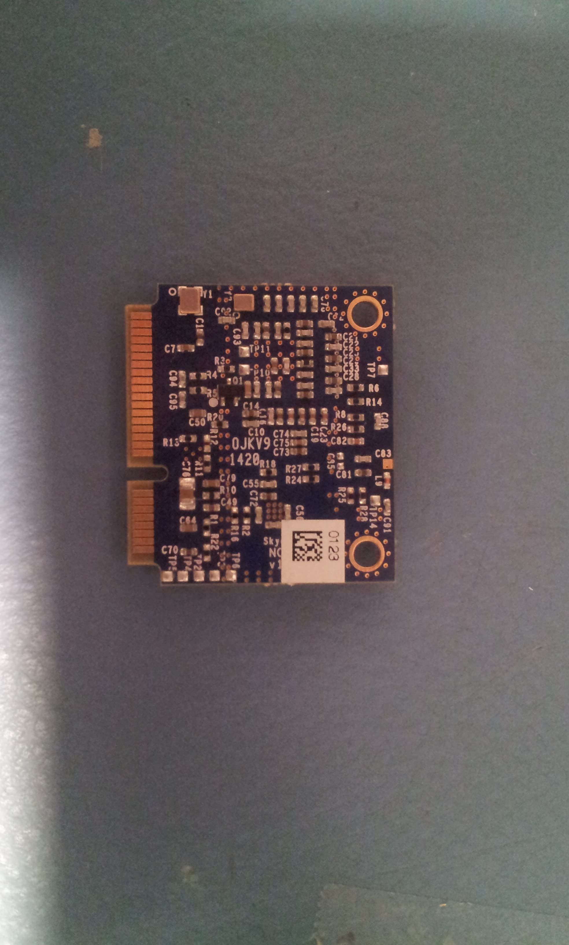
WZ4-NOVA001
Jun 07, 2015RFID Interrogator
Equipment Class
DSS - Part 15 Spread Spectrum Transmitter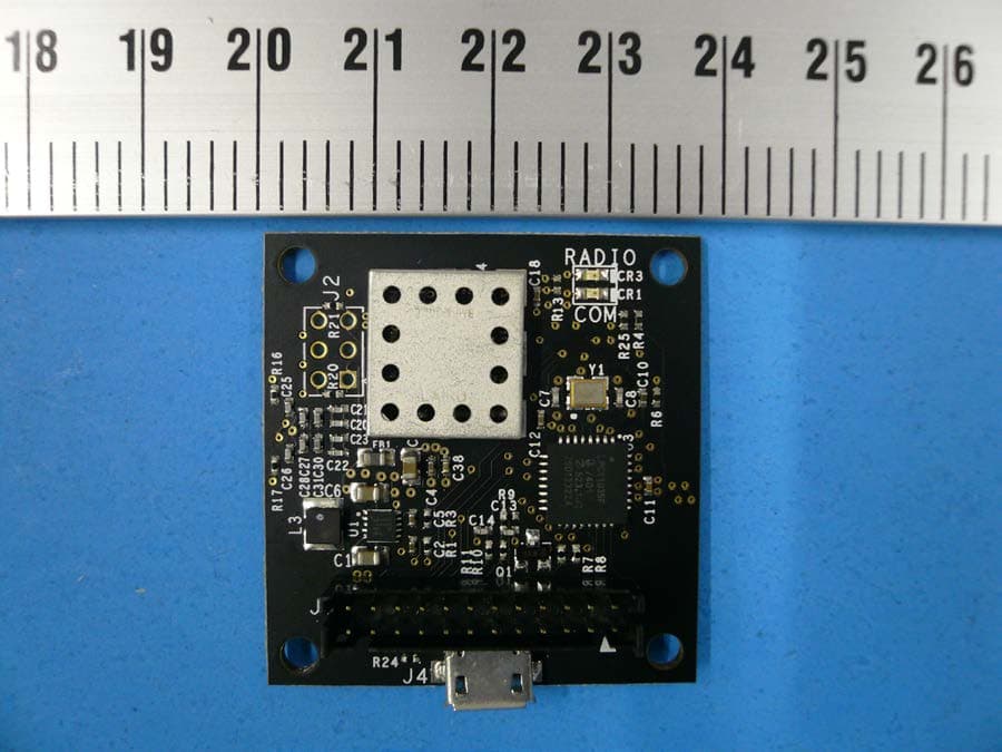
WZ4GEMINI003
May 22, 2014SkyeModule Gemini
Equipment Class
DXX - Part 15 Low Power Communication Device Transmitter