WZ4GEMINI003SkyeModule Gemini
JADAK, a business unit of Novanta Corporation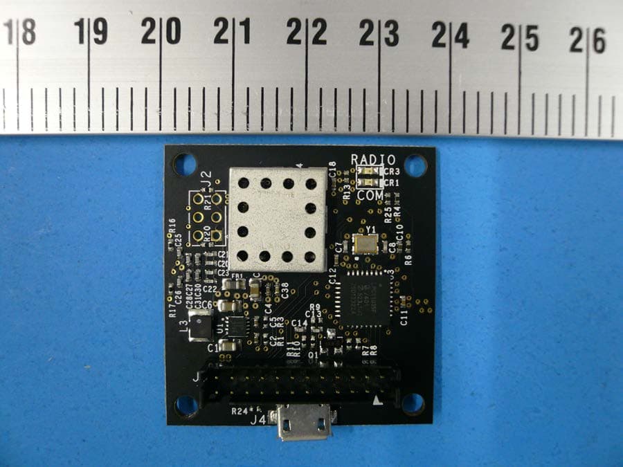
Click to zoom
Application Details
- Equipment Class
- DXX - Part 15 Low Power Communication Device Transmitter
- Date of Grant
- May 22, 2014
- Application Purpose
- Original Equipment
- Date of Application
- May 20, 2014
- Equipment Note
- SkyeModule Gemini
- Frequency Range
- 13.56000000 - 13.56000000
- Country
- United States
Documents & Files
Document Text
Text extracted from the exhibit documents filed with the FCC. Open a document above to read the original.
Users Manual
SKYEMODULE GEMINI DATASHEET VERSION 051214 SkyeModule Gemini Datasheet Page | 2 Skyetek Inc 1732 Wazee St. Ste 202 Denver, CO 80202 www.skyetek.com Main 720.328.3425 Fax:720.228.2400 COPYRIGHT INFORMATION: Copyright 2014 SkyeTek, Inc., 1732 Wazee St. Suite 202, Denver, Colorado 80202, U.S.A. All rights reserved. Version 051214 This product or document is protected by copyright and distributed under licenses restricting its use, copying, distribution, and decompilation. No part of this product or document may be reproduced in any form by any means without prior written authorization of SkyeTek and its licensors, if any. SkyeTek and SkyeWare are trademarks or registered trademarks of SkyeTek, Inc. MIFARE and NXP is a registered trademark of Royal Philips Electronics. MicroSoft and Windows are registered trademarks of Microsoft Corporation. TECHNICAL SUPPORT AND CONTACT INFORMATION SkyeTek, Inc. 1732 Wazee St. Suite 202 Denver, CO 80202 http://www.skyetek.com SALES: [email protected] TECHNICAL SUPPORT: [email protected] SkyeModule Gemini Datasheet Page | 3 Skyetek Inc 1732 Wazee St. Ste 202 Denver, CO 80202 www.skyetek.com Main 720.328.3425 Fax:720.228.2400 TABLE OF CONTENTS 1 INTRODUCTION .............................................................................................................................................. 7 1.1 GETTING STARTED .............................................................................................................................................. 7 1.2 WHY A SKYETEK MODULE? .................................................................................................................................. 7 1.3 ADDITIONAL READING ......................................................................................................................................... 8 1.4 REVISION HISTORY .............................................................................................................................................. 9 2 DEFINITION OF TERMS ................................................................................................................................. 10 3 ORDERING INFORMATION ........................................................................................................................... 11 3.1 GEMINI STANDARD PART NUMBERS ..................................................................................................................... 11 3.2 PART NUMBER DETAILS ..................................................................................................................................... 11 3.3 HOW TO BUY ................................................................................................................................................... 12 4 SKYEMODULE GEMINI OVERVIEW ................................................................................................................ 13 4.1 DESCRIPTION.................................................................................................................................................. 13 4.2 BLOCK DIAGRAM .............................................................................................................................................. 13 4.3 FEATURES ........................................................................................................................................................ 14 4.4 APPLICATIONS .................................................................................................................................................. 14 4.5 AGENCY APPROVALS ......................................................................................................................................... 14 5 MECHANICAL SPECIFICATIONS ..................................................................................................................... 15 6 PINNING INFORMATION .............................................................................................................................. 16 6.1 CONNECTOR DESCRIPTIONS ................................................................................................................................ 16 6.2 HOST INTERFACE CONNECTOR PIN MAPPING ......................................................................................................... 17 6.3 EXTERNAL ANTENNA CONNECTOR PIN MAPPING .................................................................................................... 18 6.4 USING THE GPIO PINS ...................................................................................................................................... 19 7 ENVIRONMENTAL SPECIFICATIONS .............................................................................................................. 20 7.1 ELECTROSTATIC PRECAUTIONS ............................................................................................................................. 20 7.2 GENERAL RATINGS AND OPERATING CONDITIONS ................................................................................................... 20 8 ELECTRICAL SPECIFICATIONS ........................................................................................................................ 21 8.1 ELECTRICAL CHARACTERISTICS ............................................................................................................................. 21 8.2 ABSOLUTE MAXIMUM RATINGS ........................................................................................................................... 22 9 PERFORMANCE SPECIFICATIONS .................................................................................................................. 23 9.1 TIMING SPECIFICATIONS ..................................................................................................................................... 23 9.2 RANGE SPECIFICATIONS...............................................................…
Text truncated - open the document above for the full version.
Block Diagram
Cortex M-0 Microcontroller Firmware SkyeOS SkyeModule Gemini U S B C o n n e c t o r H o s t I n t e r f a c e C o n n e c t o r I n t e r f a c e D r i v e r s Protocol Parser Tag Commands System Parameters Crypto Libraries ISO Protocol Libraries Tag Feature Libraries R a d i o D r i v e r s Radio Transceiver TRX LED MCU LED JumpersEMC Filter M a t c h i n g N e t w o r k Integrated Antenna External Antenna Connector Power Regulation V IN (1.8 – 5.5V) TTL Serial SPI I2C USB V CC (3.3V) 12 MHz XTAL PLL 48MHz 13.56 MHz GEN 27.12 MHz XTAL
Cover Letter(s)
skyetek.com 1732 Wazee St., Ste 202, Denver, CO 80202 720.328.3424 Date: April 21, 2014 Federal Communications Commission 7435 Oakland Mills Road Columbia, MD 21046 Modular Approval Letter Product: SkyeModule Gemini FCC ID: WZ4GEMINI003 To Whom It May Concern: In accordance with Section 15.212 (b), SkyeTek, Inc . believes it has met all of the requirements set out in that document for the granting of single modular approval. Specifically, the criteria set out in that document are addressed below in bold: 1. The modular transmitter must have its own RF shielding. This is intended to ensure that the module does not have to rely upon the shielding provided by the device into which it is installed in order for all modular transmitter emissions to comply with Part 15 limits. It is also intended to prevent coupling between the RF circuitry of the module and any wires or circuits in the device into which the module is installed. Such coupling may result in non- compliant operation. The Model Gemini has its own shielding covering all critical RF components. This can be seen in the photographs included in the accompanying test report. or Unit has passed spurious emissions test without shielding . 2. The modular transmitter must have buffered modulation/data inputs (if such inputs are provided) to ensure that the module will comply with Part 15 requirements under conditions of excessive data rates or over-modulation. The module Gemini has buffered modulation/data inputs provided by the microcontroller components. 3. The modular transmitter must have its own power supply regulation. This is intended to ensure that the module will comply with Part 15 requirements regardless of the design of the power supplying circuitry in the device into which the module is installed. The Gemini module incorporates its own supply regulation, and components TPS63031 provide this. 4. The modular transmitter must comply with the antenna requirements of Section 15.203 and 15.204(c). The antenna must either be permanently attached or employ a “unique” skyetek.com 1732 Wazee St., Ste 202, Denver, CO 80202 720.328.3424 antenna coupler (at all connections between the module and the antenna, including the cable). Any antenna used with the module must be approved with the module, either at the time of initial authorization or through Class II permissive change. The “professional installation” provision of Section 15.203 may not be applied to modules. The Gemini employs a “unique” antenna coupler (at all connections between the module and the antenna, including the cable). All antennas have been verified at the time of initial authorization. 5. The modular transmitter must be tested in a stand-alone configuration, i.e., the module must not be inside another device during the testing. This is intended to demonstrate that the module is capable of complying with Part 15 emission limits regardless of the device into which it is eventually installed. Unless the transmitter module will be battery powered, it must comply with the AC line conducted requirements found in Section 15.207. AC or DC power lines and data input/output lines connected to the module must not contain ferrites, unless they will be marketed with the module (see Section 15.27(a)). The length of these lines shall be length typical of actual use or, if that length is unknown, at least 10 centimeters to insure that there is no coupling between the case of the module and supporting equipment. Any accessories, peripherals, or support equipment connected to the module during testing shall be unmodified or commercially available (see Section 15.31(i)). The Gemini does not employ any ferrites or specify how your company ensures they will be implemented 6. The modular transmitter must be labeled with its own FCC ID number, and, if the FCC ID is not visible when the module is installed inside another device, then the outside of the device into which the module is installed must also display a label referring to the enclosed module. This exterior label can use wording such as the following: “Contains Transmitter Module FCC ID: “XYZMODEL1” or “Contains FCC ID: XYZMODEL1.” Any similar wording that expresses the same meaning may be used. The Grantee may either provide such a label, an example of which must be included in the application for equipment authorization, or, must provide adequate instructions along with the module which explain this requirement. In the latter case, a copy of these instructions must be included in the application for equipment authorization. The Gemini is fitted with their own labels, including the FCC ID number. User manual has instructions for host device labeling on page # 25 7. The modular transmitter must comply with any specific rule or operating requirements applicable to the transmitter and the manufacturer must provide adequate instructions along with the module to explain any such requirements. A copy of these instructions must be included in the application for equipment authorization. For example, there are skyetek.com 1732 Wazee St., Ste 202, Denver, CO 80202 720.328.3424 very strict operational and timing requirements that must be met before a transmitter is authorized for operation under Section 15.231. For instance, data transmission is prohibited, except for operation Section 15.231(e), in which case there are separate field strength level and timing requirements. Compliance with these requirements must be assured. The Gemini module has been tested to comply with all rules under Part 15. The compliance is assured by the design of the device and the user is unable to intervene to cause the device to operate incorrectly. 8. The modular transmitter must comply with any applicable RF exposure requirements. For example, FCC Rules Sections 2.1091, 2.1093 and specific Sections of Part 15, including 15.319(i), 15.407(f), 15.253(f) and 15.255(g), require that Unlicensed PCS, UNII and millimeter wave devices perform routine environmental evalu…
Text truncated - open the document above for the full version.
External Photos
TUV Rheinland Product Under Test Photo 1279 Quarry Lane, Ste. A, Pleasanton, CA 95466 Tel: (925) 249-9123, Fax: (925) 249-9124 Report Number: 31460846.001 Page 1 of 3 EUT: SkyeModule Gemini Model: SM-GM EMC / Rev 5/19/2014 1.1 Product Under Test Photo Figure 1: External Photo of EUT (Top) TUV Rheinland Product Under Test Photo 1279 Quarry Lane, Ste. A, Pleasanton, CA 95466 Tel: (925) 249-9123, Fax: (925) 249-9124 Report Number: 31460846.001 Page 2 of 3 EUT: SkyeModule Gemini Model: SM-GM EMC / Rev 5/19/2014 Figure 2: External Photo of EUT (Bottom) TUV Rheinland Product Under Test Photo 1279 Quarry Lane, Ste. A, Pleasanton, CA 95466 Tel: (925) 249-9123, Fax: (925) 249-9124 Report Number: 31460846.001 Page 3 of 3 EUT: SkyeModule Gemini Model: SM-GM EMC / Rev 5/19/2014 Figure 3: External Photo of EUT (Side)
Internal Photos
Internal Photos Top – No shield Top – With shield Bottom The antenna is the Multi-loop trace on the encompassing the circuit board.
Operational Description
SkyeModule Gemini Theory of Operation The SkyeModule Gemini is a multi-protocol RFID read/write module for use with industry standard 13.56MHz NFC tags. The low profile, small footprint and on-board antenna make the Gemini a plug and play solution for adding RFID technology into new and existing devices and equipment. The reader generates an RF field around its antenna. The RF field gives the tag power, a clock, and a way to transfer data to the reader. The tag modulates the reader’s RF field and the reader can detect this.
Test Report
Report Number: 31460846.001 Page 1 of 64 EUT: SkyeModule Gemini Model: SM-GM Report Date: April 28, 2014 FCCID: WZ4GEMINI003 Emissions Test Report EUT Name: SkyeModule Gemini Model No.: SM-GM CFR 47 Part 15.225:2013 and RSS-210:2010 Prepared for: Brad Alcorn SkyeTek, Inc. 1732 Wazee St, Ste 202 Denver, CO 80202 U.S.A. Tel: (720) 328-3425 Fax: (720) 228 2400 Prepared by: TUV Rheinland of North America, Inc. 1279 Quarry Lane, Ste. A Pleasanton, CA 94566 Tel: (925) 249-9123 Fax: (925) 249-9124 http://www.tuv.com/ Report/Issue Date: April 28, 2014 Reissue Date: May 20, 2014 Report Number: 31460846.001 Revision 2 Job#: 0000119472 Report Number: 31460846.001 Page 2 of 64 EUT: SkyeModule Gemini Model: SM-GM Report Date: April 28, 2014 FCCID: WZ4GEMINI003 Revisions Revision No. Dat e MM/DD/YYYY Reason for C hange Author 0 04/28/2014 Original Document N/A 1 05/01/2014 Revised FCC ID number from “WX4-GEMINI003” to “WX4GEMINI003” (throughout report). J. Luong 2 05/20/2014 Revised FCC ID number from “WX4GEMINI003” To “WZ4GEMINI003” (throughout report). J. Luong Not e: L atest r evision report w ill r eplace all previou s reports. Statement of Compliance Report Number: 31460846.001 Page 3 of 64 EUT: SkyeModule Gemini Model: SM-GM Report Date: April 28, 2014 FCCID: WZ4GEMINI003 Manufacturer: SkyeTek, Inc. 1732 Wazee St, Ste 202 Denver, CO 80202 (720) 328-3425 Requester / Applicant: Brad Alcorn Name of Equipment: SkyeModule Gemini Model No. SM-GM Type of Equipment: Industrial, Scientific, or Medical (ISM) Application of Regulations: CFR 47 Part 15.225:2013 and RSS-210:2010 Test Dates: March 14, 2014 to March 20, 2014 Guidance Documents: Emissions: ANSI C63.10: 2009 Test Methods: Emissions: ANSI C63.10: 2009 The electromagnetic compatibility test and documented data described in this report has been performed and recorded by TUV Rheinland, in accordance with the standards and procedures listed herein. As the responsible authorized agent of the EMC laboratory, I hereby declare that the equipment described above has been shown to be compliant with the EMC requirements of the stated regulations and standards based on these results. If any special accessories and/or modifications were required for compliance, they are listed in the Executive Summary of this report. This report must not be used to claim product endorsement by A2LA or any agency of the U.S. Government. This report contains data that are not covered by A2LA accreditation. This report shall not be reproduced except in full, without the written authorization of TUV Rheinland of North America. Jeremy Luong March 21, 2014 Conan Boyle May 20, 2014 (Reissue Date) Test Engineer Date Laboratory Signature Date Industry Canada Testing Cert #3331.02 US5254 2932M-1 Table of Contents Report Number: 31460846.001 Page 4 of 64 EUT: SkyeModule Gemini Model: SM-GM Report Date: April 28, 2014 FCCID: WZ4GEMINI003 1 Executive Summary _______________________________________________________ 7 1.1 Scope______________________________________________________________________ 7 1.2 Purpose____________________________________________________________________ 7 1.3 Summary of Test Results _____________________________________________________ 7 1.4 Special Accessories __________________________________________________________ 7 1.5 Equipment Modifications _____________________________________________________ 7 2 Laboratory Information ____________________________________________________ 8 2.1 Accreditations & Endorsements _______________________________________________ 8 US Federal Communications Commission _______________________________________________ 8 2.1.1 NIST / A2LA _____________________________________________________________________ 8 2.1.2 Canada – Industry Canada ___________________________________________________________ 8 2.1.3 Japan – VCCI _____________________________________________________________________ 8 2.1.4 2.2 Test Facilities _______________________________________________________________ 9 Emission Test Facility ______________________________________________________________ 9 2.2.1 Immunity Test Facility ______________________________________________________________ 9 2.2.2 2.3 Measurement Uncertainty ____________________________________________________ 9 Sample Calculation – radiated & conducted emissions ____________________________________ 10 2.3.1 Measurement Uncertainties _________________________________________________________ 11 2.3.2 2.4 Calibration Traceability _____________________________________________________ 11 3 Product Information ______________________________________________________ 12 3.1 Product Description ________________________________________________________ 12 3.2 Equipment Configuration ___________________________________________________ 12 3.3 Operating Mode ___________________________________________________________ 12 3.4 Unique Antenna Connector __________________________________________________ 13 Results _________________________________________________________________________ 13 3.4.1 4 Emissions ______________________________________________________________ 14 4.1 Carrier Field Strength Requirements __________________________________________ 14 Test Method _____________________________________________________________________ 14 4.1.1 Results _________________________________________________________________________ 15 4.1.2 4.2 Occupied Bandwidth _______________________________________________________ 16 Test Method _____________________________________________________________________ 16 4.2.1 Results _________________________________________________________________________ 17 4.2.2 4.3 Out-of-Band Emissions ______________________________________________________ 21 Test Method _____________________________________________________________________ 21 4.3.1 Test Result ______________________________________________________________________ 22 4.3.2 4.4 Transmitter Spurious Emissions ___________________________________…
Text truncated - open the document above for the full version.
Test Setup Photos
TUV Rheinland Test Setup Photo 1279 Quarry Lane, Ste. A, Pleasanton, CA 95466 Tel: (925) 249-9123, Fax: (925) 249-9124 Report Number: 31460846.001 Page 1 of 8 EUT: SkyeModule Gemini Model: SM-GM EMC / Rev 5/19/2014 1 Photo 1.1 Test Setup Photo Figure 1: Test Setup for 9 kHz to 30MHz (Front View) – Loop Facing EUT TUV Rheinland Test Setup Photo 1279 Quarry Lane, Ste. A, Pleasanton, CA 95466 Tel: (925) 249-9123, Fax: (925) 249-9124 Report Number: 31460846.001 Page 2 of 8 EUT: SkyeModule Gemini Model: SM-GM EMC / Rev 5/19/2014 Figure 2: Test Setup for 9 kHz to 30MHz (Rear View) – Loop Facing Away TUV Rheinland Test Setup Photo 1279 Quarry Lane, Ste. A, Pleasanton, CA 95466 Tel: (925) 249-9123, Fax: (925) 249-9124 Report Number: 31460846.001 Page 3 of 8 EUT: SkyeModule Gemini Model: SM-GM EMC / Rev 5/19/2014 Figure 3: Test Setup for 30 MHz to 1000 MHz (Front View) TUV Rheinland Test Setup Photo 1279 Quarry Lane, Ste. A, Pleasanton, CA 95466 Tel: (925) 249-9123, Fax: (925) 249-9124 Report Number: 31460846.001 Page 4 of 8 EUT: SkyeModule Gemini Model: SM-GM EMC / Rev 5/19/2014 Figure 4: Test Setup for 30 MHz to 1000 GHz (Rear View) TUV Rheinland Test Setup Photo 1279 Quarry Lane, Ste. A, Pleasanton, CA 95466 Tel: (925) 249-9123, Fax: (925) 249-9124 Report Number: 31460846.001 Page 5 of 8 EUT: SkyeModule Gemini Model: SM-GM EMC / Rev 5/19/2014 Figure 5: Test Setup for AC Conducted Emission (Front View) TUV Rheinland Test Setup Photo 1279 Quarry Lane, Ste. A, Pleasanton, CA 95466 Tel: (925) 249-9123, Fax: (925) 249-9124 Report Number: 31460846.001 Page 6 of 8 EUT: SkyeModule Gemini Model: SM-GM EMC / Rev 5/19/2014 Figure 6: Test Setup for AC Conducted Emission (Side View) TUV Rheinland Test Setup Photo 1279 Quarry Lane, Ste. A, Pleasanton, CA 95466 Tel: (925) 249-9123, Fax: (925) 249-9124 Report Number: 31460846.001 Page 7 of 8 EUT: SkyeModule Gemini Model: SM-GM EMC / Rev 5/19/2014 Figure 7: Frequency Stability Test Setup (Outside Thermal) TUV Rheinland Test Setup Photo 1279 Quarry Lane, Ste. A, Pleasanton, CA 95466 Tel: (925) 249-9123, Fax: (925) 249-9124 Report Number: 31460846.001 Page 8 of 8 EUT: SkyeModule Gemini Model: SM-GM EMC / Rev 5/19/2014 Figure 8: Frequency Stability Test Setup (Inside Thermal Chamber) RX Antenna Thermal Couple
Contact Information
Applicant
Eva Gravius(VP Engineering)
Test Firm
TUV Rheinland of North America Inc.David Spencer
Technical Specifications
| # | Rule Parts | Frequency Range | Power Output | Tolerance |
|---|---|---|---|---|
| 1 | 15C | 13.56 MHz - 13.56 MHz | 0.50 µW | 12.7200000000 ppm |
Other Applications from JADAK, a business unit of Novanta Corporation
WZ4-NOVA001
Jun 07, 2015RFID Interrogator
Equipment Class
DSS - Part 15 Spread Spectrum Transmitter
WZ4010A0001
Apr 20, 2010RFID PORTAL READER
Equipment Class
DSS - Part 15 Spread Spectrum Transmitter