WZ659300INDUCTION
Luxine (Xi'an) Electronical Co., Ltd.Application Details
- Equipment Class
- 8CC - Part 18 Consumer Device
- Date of Grant
- Jan 27, 2011
- Application Purpose
- Original Equipment
- Date of Application
- Jan 27, 2011
- Equipment Note
- INDUCTION
- Frequency Range
- 0.02000000 - 0.08000000
- Country
- China
Documents & Files
Document Text
Text extracted from the exhibit documents filed with the FCC. Open a document above to read the original.
Users Manual
ENGLISH Item No. 2350037-1 Rev 4/10 ENGLISH Operator’s Manual FOODSERVICE INDUCTION RANGE/WARMER Thank you for purchasing this Vollrath Induction Range. Before operating the equipment, read and familiarize yourself with the following operating and safety instructions. SAVE THESE INSTRUCTIONS FOR FUTURE REFERENCE. Save the original box and packaging. Use this packaging to ship the equipment if repairs are needed. ModelDescriptionVoltageHZWattsPlug 59300Countertop (US Only)12050/6018005-15P 59310Countertop (Canada Only)12050/6014405-15P Foodservice induction ranges OperatOr’s Manual 2 Function and PurPose This unit is intended to be used with induction-ready cookware (see below) with a flat, ferrous base measuring 4-1/2” (11.4 cm) to 10-1/4” (26 cm) wide. This unit is intended for use in commercial foodservice operations only. It is not intended for household, industrial or laboratory use. induction ready cookware Ferrous stainless steel Iron Cast iron unsuitable cookware Cookware with a base less than 4-1/2” (11.4 cm) Pottery, glass, aluminum, bronze or copper cookware Cookware with any type of footed base NOTE: There must be a minimum of 4” (10 cm) between the induction range and any surrounding surface to allow sufficient airflow around the unit. Blocking the airflow could overheat the unit. installation This unit is to be used on a flat, level surface. NOTE: This unit is not designed to be inclosed or built into any area. There must be a minimum of 4” (1.3 cm) of space between the rear of the induction range/warmer and any surrounding surface. There must be 1/2” (2 cm) between the bottom of the induction range/warmer and any surrounding surface. Sufficient airflow must be allowed around the unit. Blocking the airflow could cause the unit to overheat. coutertoP 1. Place the induction range/warmer on a flat stable surface. 2. Plug the power cord into a grounded electrical outlet with the matching nameplate rated voltage. NOTE: Using a voltage other than the nameplate rated voltage will cause damage to the unit. Incorrect voltage, modification to the power cord or electrical components can damage unit and will void the warranty. oPeration WARNING Electrical Shock Hazard. Keep water and other liquids from entering the inside of the unit. Liquid inside the unit could cause an electrical shock. If liquid spills or boils over onto the unit, immediately unplug the unit and remove cookware. Wipe up any liquid with a padded cloth. saFety Precautions To ensure safe operation, read the following statements and understand their meaning. This manual contains safety precautions which are explained below. Please read carefully. WARNING Warning is used to indicate the presence of a hazard that can cause severe personal injury, death, or substantial property damage if the warning is ignored. CAUTION Caution is used to indicate the presence of a hazard that will or can cause minor personal injury or property damage if the caution is ignored. NOTE Note is used to notify people of installation, operation, or maintenance information that is important but not hazard-related. For Your Safety! These precautions should be followed at all times. Failure to follow these precautions could result in injury to yourself and others or damage the equipment. To reduce risk of injury or damage to the unit: Plug only into grounded electrical outlets matching the nameplate rated voltage. As a precaution, persons using a pacemaker should stand back 12” (30 cm) from an operating unit. Studies have shown that the induction element will not disrupt a pacemaker. Keep all credit cards, driver licenses and other items with a magnetic strip away from an operating unit. The unit’s magnetic field will damage the information on these strips. The heating surface is made of a strong, non-porous material. However, should it crack or break, stop using and immediately unplug the unit. Do not leave an empty pan on an operating unit. Unit should only be used in a flat, level position. Unplug unit and let it cool before cleaning or moving. Do not touch the cooking surface. It remains hot after the unit is turned off. Do not spray controls or outside of unit with liquids or cleaning agents. Unplug when not in use. Keep unit and power cord away from open flames, electric burners or excessive heat. Do not heat sealed cans or containers as they may explode. Do not operate unattended. Closely supervise units operating in public areas and/or around children. Do not operate if unit has been damaged or is malfunctioning in any way. Do not place any objects inside the air intake or exhaust panels. Do not place weight on the control knob. Foodservice induction ranges 3 ENGLISH OperatOr’s Manual C UP button. Used to increase the power level or time depending upon the mode selected. D DOWN button. Used to decrease the power level or time depending upon the mode selected and model. E DISPLAY panel. This displays the power level, temperature, timer time or an error code, depending upon the mode selected and the model. F POWER/TEMP button. Pushing the Power/Temp button toggles between the three (3) LED lights and functions: Power control, Temperature control in ºF, Temperature control in ºC. G TIMER button. Used to switch on and start the timer function. H ºC LED light. Illuminates when the temperature in being displayed in degrees Centigrade. I ºF LED light. Illuminates when the temperature in being displayed in degrees Fahrenheit. adjusting the Power and temPerature 1. Press the ON/OFF button to turn on the unit. 2. Place induction-ready cookware on the range/warmer. A number will remain “steady on” units with a DISPLAY panel. The HEATING LED will illuminate on units with HEAT RANGE and TEMPERATURE LED lights. 3. To adjust the cooking power level from 1-20, press the up button or down button. 4. Press the POWER/TEMP button a to choose an approximate temperature 100° F – 410° F. Press the POWER/TEMP button a second time to choose an…
Text truncated - open the document above for the full version.
External Photos
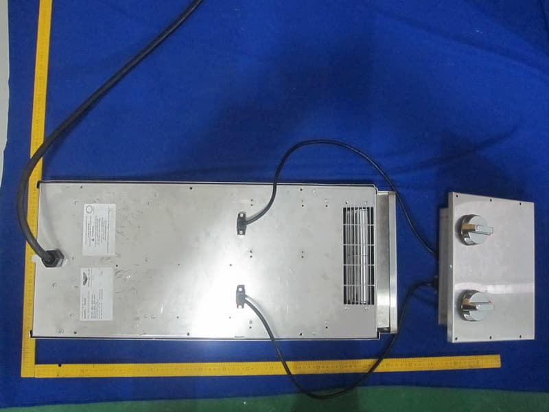
Report No.: TB-FCC108252 Page: 3 of 6 TB-RF-075-1.0 Appendix III EUT External Photographs Photo 1 Appearance of EUT Photo 2 Appearance of EUT
ID Label/Location Info
Report No.: TB-FCC108252 Page: 2 of 6 TB-RF-075-1.0 Appendix II ID Label Location FCC ID LOCATION
ID Label/Location Info
Report No.: TB-FCC108252 Page: 1 of 6 TB-RF-074-1.0 Appendix IID Label
Internal Photos
Report No.: TB-FCC108252 Page: 4 of 6 TB-RF-075-1.0 Appendix IV EUT Internal Photographs Photo 3 Inside of EUT Photo 4 Inside of EUT Report No.: TB-FCC108252 Page: 5 of 6 TB-RF-075-1.0 Photo 5 Appearance of PCB Photo 6 Appearance of PCB
Operational Description
59300/59310 Circuit Description 1. 12-2600 is the main board of 59300/59310. It contains a microchip which model is Samsung 9454. It apply PWM signal to drive IGBT. 2. 59300/59310 contain 12-2600 mian board and 12-0308 display board. EMI filter is on the main board to pass conduction. Display board was controlled by microchip.
Schematics
1234 A B C D 4321 D C B A Title NumberRevisionSize A4 Date:6-Dec-2010 Sheet of File:C:\Documents and Settings\paganiniwei\My Documents\Saibei\Hongtai2000W\displayboard1.DDBDrawn By: NC 1 DIO 2 CLK 3 STB 4 KEY1 5 KEY2 6 VDD 7 SEG1/KS1 8 SEG2/KS2 9 SEG3/KS3 10 SEG4/KS4 11 SEG5/KS5 12 SEG6/KS6 13 SEG7/KS7 14 SEG8/KS8 15 SEG9/KS9 16 SEG10/KS10 17 GND 28 GRID1 27 GRID2 26 GND 25 SEG12/GRID7 18 SEG13/GRID6 19 SEG14/GRID5 20 VDD 21 GND 22 GRID4 23 GRID3 24 U200 TM1628 R202 10K R201 10K R200 10K +5V_2+5V_2+5V_2 LC2 LC1 LC4 LED3 LED1 GND_2 KEY2 DIO/P2.0_2 CLK/P2.6_2 STB/P1.1_2 KEY2_2 +5V_2 +5V_2 GND_2 GND_2 GND_2 STB/P1.1_2 CLK/P2.6_2 DIO/P2.0_2 R203 10K LED1 LED2 C203 101 C204 101 C205 101 GND_2GND_2GND_2 EC200 220uF/25V C200 104 +5V_2 GND_2 1 2 3 4 5 6 7 8 9 10 11 12 13 14 CN201 CN14 +5V_2 +5V_2 GND_2 GND_2 STB/P1.1_2 CLK/P2.6_2 GND_2 DIO/P2.0_2 POT P2.1_2 P2.2_2 P2.3_2 P2.4_2 TIGBT/P0.0_2 SEG1 SEG2 SEG3 SEG4 SEG5 SEG6 SEG7 SEG8SEG1 SEG2 SEG3 SEG4 SEG5 SEG6 SEG7SEG8 LC1 LC2 LC3 LC4 S200DECSEG1 S203ADDSEG1 S201TIMERSEG2 S202ON/OFFSEG3 S204TEMPSEG2 R204 10K GND_2 KEY1 D200TIMER D201ON/OFF D202TEMP LED2 LC3KEY1_2 LC5 LC5 LC6 LC6 LED3 A 11 B 7 C 4 D 2 E 1 F 10 G 5 DP 3 DIG1 12 DIG2 9 DIG3 8 LED4 LED888-LUX 12345678 A B C D 87654321 D C B A Title NumberRevisionSize A2 Date:6-Dec-2010 Sheet of File:C:\Documents and Settings\paganiniwei\My Documents\Saibei\Hongtai2000W\MAINBO~1.DDBDrawn By: 1 2 J1 L 1 2J2 N CX1 8uF/275V CY1 102M/250V~ CY2 102M/250V~ D1 1N4007 D2 1N4007 C D3 1N4007 1 2 M1 20D431K R41 330K/2W 5 2A 8 1A T2 CTI 1 2 3 4 BD GBJ2506 L3 300uH C18 8uF/400V R35 330K 1W R9 10K C19 0.3uF/1600V R8 10R +5V +18V R6 560K 1W R7 240K 1W R10 2.2K +18V EC8 220uF/25V R2 330K 1W R37 240K 1W C8 221 R28 6.8K R30 9.53K R29 9.53K R27 620 C13 102/1KV R26 6.8K C R19 330K C4 224 R13 2.2K +5V C9104 同步检测 功率输出 R1 330K 1W R3 330K 1W ZD2 18V/0.5W C10104 + EC11 10uF/50V R38 100 +5V +18V D5 UF1K EC2 100uF/25V EC5 100uF/25V EC4 220uF/25V C1 104 C2 104 EC3 100uF/25V Vin 1 G N D 2 +5V 3 IC2 78M05+5V EC1 22uF/400V D4 UF1K C14 103/1KV D6 UF1K +18V R4 100K/2W EC10 100uF/25V +5V 1 2 CN1 FAN 1 2 CN2 Q1 NPN8050 R22 620 +5V R16 1K +18V +5V C12 222J +5V R23 68K Q2 NPN8050 1 2 CN4 +5V R33 3.6K/1% R34 10K C3 104 +18V EC6 2.2uF/50V R17 35.7K R20 100 C11 104 C5 104 2 1 3 D10 BAV70 CUR +5V R24 2.2K R25 2.2K R15 2 0 0 K R12 100 C U R CUR ENA 1 INA 2 GND 3 INB 4 OUTB 5 VDD 6 OUTA 7 ENB 8 IC5 FAN3224 C C 10 11 3 1 2 13 IC3D LM339 6 7 3 1 2 1 IC3B LM339 8 9 3 1 2 14 IC3C LM339 C20 104 VIN_CHK TIGBT PAN_CHK TPAN PWM BUZ 1 2 J3 L N JINJOUT 1 2 3 4 JIN 1 2 3 4 JOUT IGBT BZ BELL F1 LF 314020 21 3 D7 BAV70 CY5 472 TIGBT/P0.0 VIN_CHK GND 1 XIN/P1.0 2 XOUT/P1.1 3 RESET/P1.2 4 P2.0/T0 5 P2.1 6 P2.2 7 P2.3 8 P2.4 9 P2.5 10 P2.6/ADC8/CLO 11 P0.7/ADC7 12 P0.6/ADC6/PWM 13 P0.5/ADC5 14 P0.4/ADC4 15 P0.3/ADC3 16 P0.2/ADC2 17 P0.1/ADC1/INT1 18 P0.0/ADC0/INT0 19 VDD 20 IC1 S3F9454 GND SURGE_PRO PAN_CHK SURGE_PRO VIN_CHK SURGE_PRO STB/P1.1 POT/P2.6 DIO/P2.0 FAN FAN 1 2 3 4 5 6 7 8 9 10 11 12 13 14 CN3 +5V +5V GND GND STB/P1.1 CLK/P2.4 GND DIO/P2.0 POT/P2.6 P2.1 P2.2 LED/P2.3 CLK/P2.4 TIGBT/P0.0 P2.1 P2.2 LED/P2.3 CLK/P2.4 方案1:显示+开关按键 STB/P1.1 CLK/P2.6 DIO/P2.0 方案2:显示+触摸按键 STB/P1.1 CLK/P2.6 DIO/P2.0 P2.1 P2.2 P2.3 P2.4 方案3:显示+旋电位器 STB/P1.1 P2.x DIO/P2.0 CLK/P2.6 方案4:显示+旋编码器 STB/P1.1 CLK/P2.6 DIO/P2.0 TIGBT/P0.0 P2.x 4 3 5 6 8 72 1 60T 6T 11T 7T 0.2mm单股 0.16mm单股 0.3mm双股并绕 0.3mm三股并绕 T1 EE20磁芯/卧式骨架 D 6 D 7 D 8 VCC 2 VSTR 5 IPK 4 VFB 3 G N D 1 IC4 FSDM0265 R5 10K C6 100pF/1KV R14 22 C7 104 CX2 5uF/275V 锅具 72uH 4 5 3 1 2 2 IC3A LM339 21 3 D9 BAV70 21 3 D8 BAV70 R21 510/1W 1 2 3 CN5 POT GND KNOB 1 2 CN6 LED +5V LED/P2.3 R43 2.2K/1% +5V C22 104 R44 68K C23 104 GND KNOBPOT/P2.6 GND R32 68K R31 68K C15 104 C16 104 R36 22\1W L2 300uH L4 300uH R45 68K GND R11 52.3R EC7 10uF/50V R39 68K R42 10K C21 104 C U R R40 52.3R CY4 222 CY3 222 14 23 L1 7.5mH R46 10K C 4 E 3 2 K 1 A U1 PC817-1 R47 30K 2 1 3 U2 TL431 +18V C24 104 R48 62K R49 10K +18V R50 240K/2W
Test Report
Shenzhen Toby Technology Co., Ltd. Report No.: TB-FCC110224 Page: 1 of 18 TB-RF-074-1.0 10/F., A Block, Jiada R & D Bldg., No.5 Songpingshan Road, Science & Technology Park, Nanshan District, Shenzhen, China Tel: +86 75526509301 Fax: +86 75526509195 FCC Test Report FCC ID: WZ659300 Report No. : TB-FCC110224 Applicant : Luxine (Xi’an) Electronics Co., Ltd. Equipment Under Test (EUT) EUT Name : Induction Cooker Model No. : 59300 Serial No. : 59310 Brand Name : VOLLRATH Receipt Date : 2010-12-20 Test Date : 2010-12-21 to 2011-01-06 Issue Date : 2011-01-07 Standards : FCC Part 18 : 2008 Method : FCC OST/MP-5:1986 Conclusions : PASS In the configuration tested, the EUT complied with the standards specified above, The EUT technically complies with the FCC requirements Test/Witness Engineer Ray Lai (Engineer) : Approved& Authorized Justin Zhang (Manager) : This report details the results of the testing carried out on one sample. The results contained in this test report do not relate to other samples of the same product. The manufacturer should ensure that all products in series production are in conformity with the product sample detailed in the report. Report No.: TB-FCC110224 Page: 2 of 18 TB-RF-074-1.0 Contents CONTENTS.............................................................................................................................................2 1. GENERAL INFORMATION ABOUT EUT.............................................................................3 1.1 Client Information.................................................................................................................3 1.2 General Description of EUT (Equipment Under Test)...................................................3 1.3 Block Diagram Showing the Configuration of System Tested......................................4 1.4 Description of Support Units..............................................................................................4 1.5 Description of Test Mode....................................................................................................4 1.6 Test Location........................................................................................................................5 2. TEST SUMMARY.......................................................................................................................6 3. CONDUCTED EMISSION TEST.............................................................................................7 3.1 Test Standard and Limit......................................................................................................7 3.2 Test Setup.............................................................................................................................7 3.3 Test Procedure.....................................................................................................................7 3.4 Deviation...............................................................................................................................8 3.5 Test Equipment Used..........................................................................................................8 3.5 Test Data...............................................................................................................................8 Test ................................................................................................................................................9 4. RADIATED EMISSION TEST................................................................................................13 4.1 Test Standard and Limit....................................................................................................13 4.2 Test Setup...........................................................................................................................13 4.3 Test Procedure...................................................................................................................13 4.4 Deviation.............................................................................................................................13 4.5 Test Equipment..................................................................................................................14 4.6 Test Condition....................................................................................................................14 Report No.: TB-FCC110224 Page: 3 of 18 TB-RF-074-1.0 1. General Information About EUT 1.1 Client Information Applicant : Luxine (Xi’an) Electronics Co., Ltd. Address : 4th Floor, Building B, Seeker Industrial Park, 2nd JinYe Rd, Hi-tech Development Zone, Xi’an, China Manufacturer : Luxine (Xi’an) Electronics Co., Ltd. Address : 4th Floor, Building B, Seeker Industrial Park, 2nd JinYe Rd, Hi-tech Development Zone, Xi’an, China 1.2 General Description of EUT (Equipment Under Test) EUT Name : Induction Cooker Model No. : 59300 Serial No. : 59310 Model difference : The only difference is the power. 59300:1800W (AC 120V/15A), 59310:1440W (AC 120V/12A) Power Supply : AC 120V, 60Hz Power : 1800W Connecting I/O Port(s) : Please refer to the User's Manual Note: For a more detailed features description, please refer to the manufacturer’s specifications or the User’s Manual. Report No.: TB-FCC110224 Page: 4 of 18 TB-RF-074-1.0 1.3 Block Diagram Showing the Configuration of System Tested 1.4 Description of Support Units The EUT has been tested with water up to 80% of the maximum capacity of the boiler. 1.5 Description of Test Mode To investigate the maximum EMI emission characteristics generates from EUT, the test system was pre-scanning tested base on the consideration of the EUT operation mode, and the worst Case is when the EUT is operation with the maximum power, so the conducted and radiated emission data of bellow only showed the worst case. LISN AC Power Receiver Conducted Emission Test Radiated Emission Test AC Power Report No.: TB-FCC110224 Page: 5 of 18 TB-RF-074-1.0 1.6…
Text truncated - open the document above for the full version.
Test Setup Photos
Report No.: TB-FCC108252 Page: 6 of 6 TB-RF-075-1.0 Appendix V EUT Test Photographs Photo of Setup for Radiated Emission Photo of Setup for Conducted Emission
Contact Information
Applicant
Wei Gang(R&D Manager)
Test Firm
Shenzhen Huatongwei International Insp. Co., LtdMoffy Yu
Technical Specifications
| # | Rule Parts | Frequency Range | Power Output |
|---|---|---|---|
| 1 | 18 | 0.02 MHz - 0.08 MHz | - |
Other Applications from Luxine (Xi'an) Electronical Co., Ltd.
WZ6912HIMU
Feb 23, 2011INDUCTION RANGE
Equipment Class
8CC - Part 18 Consumer Device
WZ6-69547
Jan 27, 2011INDUCTION
Equipment Class
8CC - Part 18 Consumer Device