WZ6912HIMUINDUCTION RANGE
Luxine (Xi'an) Electronical Co., Ltd.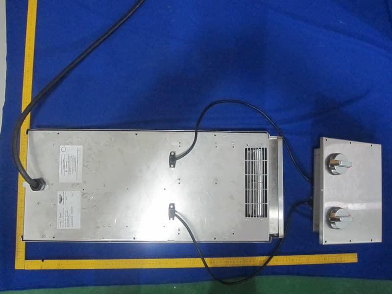
Click to zoom
Application Details
- Equipment Class
- 8CC - Part 18 Consumer Device
- Date of Grant
- Feb 23, 2011
- Application Purpose
- Original Equipment
- Date of Application
- Feb 23, 2011
- Equipment Note
- INDUCTION RANGE
- Frequency Range
- 0.02000000 - 0.08000000
- Country
- China
Documents & Files
Document Text
Text extracted from the exhibit documents filed with the FCC. Open a document above to read the original.
Users Manual
Draft Copy Operator’s Manual Item No. 2350095-1 en Rev 02/11 ENGLISH BACK OF THE HOUSE BENCH INDUCTION RANGES Thank you for purchasing this Vollrath Induction Range. Before operating the unit, read and familiarize yourself with the following operating and safety instructions. SAVE THE ORIGINAL BOX AND PACKAGING. Use this packaging to ship the unit if repairs are needed. SAVE THESE INSTRUCTIONS FOR FUTURE REFERENCE. ItemDescriptionVoltageHZAmps Watts per HobPlug 912HIMCBench – 2 Hob208 - 24050/6024.02,500 - 2,9006-30P 912HIDCBench – 2 Hob208 - 24050/6024.02,500 - 2,9006-30P Draft Copy Foodservice induction ranges OperatOr’s Manual 2 Safety PrecautionS To ensure safe operation, read the following statements and understand their meaning. This manual contains safety precautions which are explained below. Please read carefully. WARNING Warning is used to indicate the presence of a hazard that can cause severe personal injury, death, or substantial property damage if the warning is ignored. CAUTION Caution is used to indicate the presence of a hazard that will or can cause minor personal injury or property damage if the caution is ignored. NOTE Note is used to notify people of installation, operation, or maintenance information that is important but not hazard-related. For Your Safety! These precautions should be followed at all times. Failure to follow these precautions could result in injury to yourself and others. To reduce risk of injury or damage to the unit: Plug only into grounded electrical outlets matching the nameplate rated voltage. Each induction unit should have a separate circuit. Do not use an extension cord with this equipment. Do not plug this equipment into a power strip or multi-outlet power cord. As a precaution, persons using a pacemaker should stand back 12” (30 cm) from an operating unit. Studies have shown that the induction element will not disrupt a pacemaker. Keep all credit cards, driver liscences and other items with a magnetic strip away from an operating unit. The unit’s magnetic field will damage the information on these strips. The heating surface is made of a strong, non-porous material. However, should it crack or break, stop using and immediately unplug the unit. Do not leave an empty pan on an operating unit. Unit should only be used in a flat, level position. Unplug unit and let it cool before cleaning or moving. Do not touch the cooking surface. It remains hot after the unit is turned off. Do not spray controls or outside of unit with liquids or cleaning agents. Unplug when not in use. Keep unit and power cord away from open flames, electric burners or excessive heat. Do not heat sealed cans or containers as they may explode. Do not operate unattended. Closely supervise units operating in public areas and/or around children. Do not operate if unit has been damaged or is malfunctioning in any way. Do not place any objects inside the air intake or exhaust panels. Do not place weight on the control knob. or knob guard FCC Statement ~ This product may cause interference to radio equipment and should not be installed near maritime safety communications equipment or other critical navigation or communication equipment operating between 0.45-30 MHz . function and PurPoSe This unit is intended to be used with induction-ready cookware (see below) with a flat, ferrous base measuring 4-1/2” (11.4 cm) to 10-1/4” (26 cm) wide. This unit is intended for use in commercial foodservice operations only. It is not intended for household, industrial or laboratory use. induction ready cookware Ferrous stainless steel Iron Cast iron unsuitable cookware Cookware with a base less than 4-1/2” (11.4 cm) Pottery, glass, aluminum, bronze or copper cookware Cookware with any type of footed base NOTE: There must be a minimum of 4” (10 cm) between the induction range and any surrounding surface to allow sufficient airflow around the unit. Blocking the airflow could overheat the unit. inStallation 1. Install and secure the legs to the base of the unit. 2. Place the induction range/warmer on a flat stable surface at a suitable and safe height. 3. Level the equipment using the adjustable feet. NOTE: This unit is not designed to be inclosed or built into any area. There must be a minimum of 4” (10 cm) of space between the rear of the induction warmer and any surrounding surface. Sufficient airflow must be allowed around the unit. Blocking the airflow could cause the unit to overheat. 4. Plug the power cord into a grounded electrical outlet with the matching nameplate rated voltage. NOTE: Using a voltage other than the nameplate rated voltage will cause damage to the unit. Incorrect voltage, modification to the power cord or electrical components can damage unit and will void the warranty. Induction units are to use a separate dedicated circuit. oPeration WARNING Electrical Shock Hazard. Keep water and other liquids from entering the inside of the unit. Liquid inside the unit could cause an electrical shock. If liquid spills or boils over onto the unit, immediately unplug the unit and remove cookware. Wipe up any liquid with a padded cloth. 1. Place the induction-ready cookware containing food in the center position of the hob(s) to be used. NOTE: Do not pre-heat empty cookware. Because of the speed and efficiency of the induction range, cookware can very quickly overheat and be damaged. Do not drop cooking utensils or other objects onto the cooking surface. The strong, non-porous surface will break. The warranty does not cover this type of abuse. Draft Copy Foodservice induction ranges 3 ENGLISH OperatOr’s Manual digital control Model on o on o temp power timer timer temp power G H I J B F D A E C Figure 2. Digital Model Control Panel A ON/OFF button. Press to turn unit on. An LED above the control will illuminate when switched on. B ON LED light. Illuminates when the power is switched on. C POWER/TEMP button. Used to change the mode and display panel from power …
Text truncated - open the document above for the full version.
Cover Letter(s)
Luxine(Xi’an) Electronical Co., Ltd. 4 th Floor, Building B, Seeker Industrial Park, 2 nd JinYe Rd, Hi-tech Development Zone,Xi’an, China (FCC ID:WZ6912HIMU) Model Declaration Letter We, the undersigning company Company Name: Luxine(Xi’an) Electronical Co., Ltd Address: 4th Floor, Building B, Seeker Industrial Park, 2 nd JinYe Rd, Hi-tech Development Zone, Xi’an, China Hereby confirm that the following products: Product description: Induction Type designation: 912HIMU, 912HIDC, 912HIMC, 912HIDU That All versions of the Model 912HIMU, 912HIDC, 912HIMC and 912HIDU are electrically equal and only difference is the Control Panel. 912HIDC 2-hob BOH Induction range-digital control for Canada 912HIMC 2-hob BOH Induction range-manual control for Canada 912HIDU 2-hob BOH Induction range-digital control for U.S. 912HIMU 2-hob BOH Induction range-manual control for U.S. Luxine(Xi’an) Electronical Co., Ltd ------------------------------- W ei Gang (R&D Manager)
Cover Letter(s)
Luxine(Xi’an) Electronical CO., Ltd 4 th Floor, Building B, Seeker Industrial Park, 2 nd JinYe Rd, Hi-tech Development Zone, Xi’an, China (FCC ID:WZ6912HIMU) POWER OF ATTORNEY Jan. 03,2011 Federal Communications Commission Authorization and Evaluation Division 7435 Oakland Mills Road Columbia,MD 21046 To Whom It May Concern: We, the undersigned, hereby authorize Shenzhen TOBY Technology Co., Ltd. (MR. Justin ZHANG) on our behalf, to apply to the Federal Communications Commission on our equipment. Any and all acts carried out by Shenzhen TOBY Technology Co., Ltd. (Mr. Justin Zhang) on our behalf shall have the same effect as acts of our own. This authorization expires on Nov 03, 2011. This is to advise that we are in full compliance with the Anti-Drug Abuse Act. We, Luxine (Xi’an) Electronical CO., Ltd., are not subject to a denial of federal benefits pursuant to Section 5301 of the Anti-Drug Act of 1988, 21 USC853a, and no party to the application is subject to a denial of federal benefits pursuant to that section. Sincerely, Luxine (Xi’an) Electronical CO., Ltd ------------------------------- Wei Gang (R&D Manager)
External Photos
Report No.: TB-FCC110296 Page: 3 of 7 TB-RF-075-1.0 Appendix III EUT External Photographs Photo 1 Appearance of EUT Photo 2 Appearance of EUT
ID Label/Location Info
Report No.: TB-FCC110296 Page: 1 of 7 TB-RF-074-1.0 Appendix IID Label
ID Label/Location Info
Report No.: TB-FCC110296 Page: 2 of 7 TB-RF-075-1.0 Appendix II ID Label Location FCC ID LOCATION
Internal Photos
Report No.: TB-FCC110296 Page: 4 of 7 TB-RF-075-1.0 Appendix IV EUT Internal Photographs Photo 3 Inside of EUT Photo 4 Inside of EUT Report No.: TB-FCC110296 Page: 5 of 7 TB-RF-075-1.0 Photo 5 Appearance of PCB Photo 6 Appearance of PCB Report No.: TB-FCC110296 Page: 6 of 7 TB-RF-075-1.0 Photo 7 Appearance of PCB
Operational Description
BOH (Back of House) 912HIMU circuit description 12-2100 is the main board of the BOH 912HIMU. It contains a MCU to control the circuit. The power of the circuit will be controlled by PWM signal. EMI board is between the main board and the power input, it helps to block the interference from the main circuit to the power source.
Schematics
123456789101112 A B C D 121110987654321 D C B A Z13 SMAJ9A D23 BAV70 C59 0.1uF C44 0.1uF 1 2 AC2 1287 1 2 AC1 1287 Z12 SMAJ5A 1 2 J7 DCFAN2 1 2 J5 DCFAN1 C11 680pF Z9 SMAJ28A D20 BAV70 D2 BAV70 D22 BAV70 C3 0.1uF E17 220uF/25V D19 BAV70 R50 22 C41 0.1uF R58 34.8K R59 6.20K C40 0.1uF R62 34.8K D12 BAV70 1 3 2U4 ZR431 S 8 S 7 D 5 S 1 S 2 S 3 C 4 U14 TOP224P C38 0.1uF R9 4.75K R8 4.75K 1 2 3 J2 POT C4 0.1uF/250V C37 680pF E1 47uF/25V 1 2 3U9 LM431 Z8 P6KE200 C2 0.1uF R1 68 R32 4.75K 1 2 J4 TRLD Z7 ZM4748ACT R3620K Q6 MMBF170 R24 2.21K R27 110 BUZZER 5 2A 8 1A T2 CTI F1 FUSE/1A AC 2 AC 1 + 3 - 4 BR1 MB506W C42 0.1uF R25 2.21K R26 2.21K R31 110 C39 0.1uF R29 2.21K R28 8.2K D11 MUR1100E AC 1 AC 2 + 3 - 4 BR2 SDB104 2 1 4 3 U5 CMC/FE11 47uF/400V D9 31DQ10 E10 220uF/25V E9 220uF/25V C14 0.1uF COMP 1 VFB 2 IS 3 RTCT 4 VREF 8 VCC 7 OUT 6 GND 5 U13 UC3845D8 R10 4.75K C13 0.1uF C121nF Z1 Z6 Z5 Z4 Z3 Z2 R7 22 Q5 MMBF170 105 9 2 1 4 3 6 T4 EEL16 R6 2.21K E8 E7 E6 E5 R5 2.21K E4 E3 R4 2.21K E2 33uF/25V C10 C9 C8 C7 C6 C5 1 2 3 4 JOUT2 1 23 4 JOUT1 G C E Q1 IGBT G C E Q3 IGBT G C E Q2 IGBT G C E Q4 IGBT CSA 47nF CSB 47nF CSC 47nF CSD 47nF CB14.7uF/400VCB24.7uF/400V CR1 0.14uF CR2 0.14uF CR3 0.14uF 1 2 3 4 T3 CTO VIN+ 1 VIN- 2 VCC1 3 GND1 4 /RSET 5 /FALT 6 LED1 7 GND 8 VEE 9 VEE 10 VOUT 11 VC 12 VCC2 13 DESAT 14 LED2 15 VE 16 U16HCPL316J R1112.1K R1212.1K R1322 C15 0.1uF C16 0.1uF C17 0.1uF D5 MURS160T3 C18 0.1uFC19 0.1uF C20 0.1uF C21 0.1uF D6 MURS160T3 C22 0.1uF C23 0.1uF C24 0.1uF R1422 R1512.1K R1612.1K VIN+ 1 VIN- 2 VCC1 3 GND1 4 /RSET 5 /FALT 6 LED1 7 GND 8 VEE 9 VEE 10 VOUT 11 VC 12 VCC2 13 DESAT 14 LED2 15 VE 16 U17HCPL316J VIN+ 1 VIN- 2 VCC1 3 GND1 4 /RSET 5 /FALT 6 LED1 7 GND 8 VEE 9 VEE 10 VOUT 11 VC 12 VCC2 13 DESAT 14 LED2 15 VE 16 U18HCPL316J R1712.1K R1812.1K R1922 C25 0.1uF C26 0.1uF C27 0.1uF D7 MURS160T3 C28 0.1uFC29 0.1uF C30 0.1uF C31 1nF R20 2.21K C32 0.1uF D8 MURS160T3 C33 0.1uF C34 0.1uF C35 0.1uF R2122 R2212.1K R2312.1K VIN+ 1 VIN- 2 VCC1 3 GND1 4 /RSET 5 /FALT 6 LED1 7 GND 8 VEE 9 VEE 10 VOUT 11 VC 12 VCC2 13 DESAT 14 LED2 15 VE 16 U19HCPL316J E13 33uF/25V Vin 1 GND 2 VOUT 3 U11 NJM7805DLA Vin 1 GND 2 VOUT 3 U12 NJM7809DLA E14 33uF/25V EA/VP 35 XTAL1 21 XTAL2 20 RESET 10 P37RD 19 P36WR 18 P32 14 P33 15 P34 16 P35 17 P10 2 P11 3 P12 4 P13 5 P14 6 P15 7 P16 8 P17 9 P00 43 P01 42 P02 41 P03 40 P04 39 P05 38 P06 37 P07 36 P20 24 P21 25 P22 26 P23 27 P24 28 P25 29 P26 30 P27 31 PSEN 32 ALE/P 33 P31TXD 13 P30RXD 11 VCC 44 NC 23 NC 1 GND 22 NC 12 NC 34 U1 AT89SC52 R33 1.1K Q11 MMBT4401 R34 1.1K R35 1.1K Q9 MMBT4401 Q10 MMBT4401 C45 0.1uF C46 0.1uF E15 33uF/25V R36 34.8K 89 U15D C47 0.1uF C48 0.1uF C49 0.1uFINV 1 N.I 2 OSC 3 CL/+ 4 CL/- 5 RT 6 CT 7 GND 8 COMP 9 SHUT 10 EA 11 CA 12 CB 13 EB 14 VIN 15 VREF 16 U20 SG3524D C50 560pF R37 51.1K R38 4.75K R3975K R40150K R41300K R421.1M R432.2M R44620K 12 7 14 U15A DM7406M 34 U15B 56 U15C 1011 U15E 1213 U15F R45 9.09K R46 4.3M C52 33pF/COG C53 33pF/COG U10 8MHZ R48 4.75K E1233uF/25V C56 0.1uF C58 0.1uF R49 100K R51 2.21K R52 52.3C60 0.1uF R53 2.21K C62 0.1uF R55 34.8K R47 10/0.5W R30 3.48K C54 0.1uF C51 0.1uF CB31uF/400 1 2 3 4 5 6 7 8 9 10 11 12 13 14 J1 14PIN U3 NEC2501 101 9 2 4 6 57 T1 LTEEER28L Q7 MMBF170 R2 2.2K 1 2 J3 RELAY C55 0.1uF D17 BAV70 D16 BAW56D13 BAW56 D14 BAV70 D4 BAV70 CH0 1 CH1 2 CH2 3 CH3 4 DI 17 DO 14 CLK 16 SARS 15 VREFI 12 /SE 13 VREFO 19 DGND 10 AGND 11 VCC 20 CH4 5 CH6 7 CH7 8 COM 9 /CS 18 CH5 6 U2 ADC08038 C1 0.1uF R60 4.75K Q8 MMBF170R61 2.21K R56 150K C57 0.1uF 1 2 SW1 SIP2 R63 R54 34.8K RT1 100K D15 BAV70 1 2 J6 (LED) D3 BAV70 D21 BAV70 Z10 SMAJ28A D1 BAV70 Z11 SMAJ28A D10 BAV70 E16 33uF/25V 12VG 12VG IV GND DBT DBT GND GND VREF A VREF A LED 90C SHUT DOWN GND +5V /RST /WORK KONOF MTA .156" (3.96mm) A19950 (HOUSING) A1971 (HEADER) A1922 (HEADER) A19492 (HOUSING) A19490(HOUS) A1921(HEADER) A19491 (HOUSING) 12VG GND KONOF DC2GND +5V BUZ BUZ CTI2CTI1 KDOWN KUP KONOF DISP DATA CLK KNOB +5V OUTBCOUTAD +5V +5V AC2 AC1 DC- DC+ 12VGGND DC1 DC2 DC1 AC2 AC1 GND MOSG MOSG 12VG Output freq.: 150KHz Duty: 45% VBDN VAP VCP VCN R L DC- VBDP 12VG GND 12VG GND VAN GATEA GATEB GATEC GATED CTO1CTO2 DC+ DC- LR VBDN VBDN VBDN GATEB L VBDP VBDP DB DC- DC- DBVBDPVBDN VBDP /RST /FLT GND GND +5V /FLT OUTBC GND +5V+5V GND OUTAD /FLT +5V GND GND /FLT /RST VBDP VBDNVBDPDD DC- DC- DD VBDP VBDP R GATED VBDN VBDN VBDN VCN VCN VCN GATEC DC+ VCP VCP DC R R DCVCPVCN VCP /RST /FLT GND GND +5V /FLT OUTBC GND +5V+5V +5V GND /FLT OUTAD /FLT +5V GND GND /FLT /RST VAP VANVAPDA L L DA VAP VAP DC+ GATEA VAN VAN VAN +5V+9V12VG GND KT/P/RST /WORK XT2 XT1 RST FQS7 FQS6 FQS5 FQS4 FQS3 FQS2 FQS1 FQS0 LDT POT PWR DUTY GND GND +5V GND FQS0 GND GND /WORK GND GND N.I COMP OUTAD OUTBC COMP N.I GND +9V FQS2 FQS3 FQS1 FQS4 FQS5 FQS6 +5V GND FQS7 DUTY KTIME KDOWN KUP KONOF DISP CLK XT1 XT2 DATA RST +5V /FLT USE 10K/1TURN POT POT KNOB +5V HST CTI1CTI2 GND PWR LDT +5V CTO1 C-O GND CTO2 GND 100K/200C THERMISTER +5V GND +5V Z2,Z3,Z4: ZM4750ACT Z1,Z5,Z6: ZM4733ACT E3--E8: 33uF/25V/D C5--C10: 0.1uF/0805 KTIME KT/P LED GND GND +5V GND HST C-O +5V DC2 FANAC FANAC +9V MTA .100" MTA 0.1" (2.54mm) MTA .100" A19470 (HEADER) GND GND+5V GND +5V +5V ADC ADC /ADCS /ADCS ADC GND GND GND FANDC FANDC IV +5V INPUT AIR FILTER AIRT +5V SV SV GND Q12 MMBF170 Schematic for NEWF8W.PCB Date: Oct 10, 2007 Ver: NEWF8W 10/10/07 UnRegistered 1234 A B C D 4321 D C B A R7 22 1 2 AC2 1287 1 2 AC1 1287 1 2 LINE1 8196 1 2 LINE2 8196 CX4 1uF 1 2 4 3 L4 CMC CX1 0.1uF 1 2 4 3 L1 CMC CX3 2.2uF L3 80uH CX2 2.2uF 1 2 MOV1 F1 LF 314020 R1 68K CY1 470pF CY2 470pF L2 80uH 1 2 FAN1 RELAY L5 80uH CY3 470pF CY4 470pF F2 LF 314020 1 2 MOV2 CX6 2.2uF L6 80uH CX7 2.2uF 1 2 4 3 L9 CMC 1 2 4 3 L8 CMC CX8 1uF 1 2 AC3 1287 1 2 AC4 1287 F3 FUSE/1A 1 2 J1 1 2 J2 D3 1N4148 Order #: AZ743-2C-6D AC 1 AC 2 + 3 - 4 D2 RB152 AC 1 AC 2 + 3 - 4 D1 RB152 CY5 100pF CY6 100pF CY7 100pF CY8 100pF 1 2 FAN2 1 2 4 3 L7 CMC UnRegistered
Test Report
Shenzhen Toby Technology Co., Ltd. Report No.: TB-FCC110296 Page: 1 of 14 TB-RF-074-1.0 10/F., A Block, Jiada R & D Bldg., No.5 Songpingshan Road, Science & Technology Park, Nanshan District, Shenzhen, China Tel: +86 75526509301 Fax: +86 75526509195 FCC Test Report FCC ID: WZ6912HIMU Report No. : TB-FCC110296 Applicant : Luxine (Xi’an) Electronics Co., Ltd. Equipment Under Test (EUT) EUT Name : Induction Cooker Model No. : 912HIMU Serial No. : 912HIDC, 912HIMC, 912HIDU Brand Name : VOLLRATH Receipt Date : 2011-01-25 Test Date : 2011-02-09 to 2011-02-14 Issue Date : 2011-02-15 Standards : FCC Part 18 : 2008 Method : FCC OST/MP-5:1986 Conclusions : PASS In the configuration tested, the EUT complied with the standards specified above, The EUT technically complies with the FCC requirements Test/Witness Engineer Ray Lai (Engineer) : Approved& Authorized Justin Zhang (Manager) : This report details the results of the testing carried out on one sample. The results contained in this test report do not relate to other samples of the same product. The manufacturer should ensure that all products in series production are in conformity with the product sample detailed in the report. Report No.: TB-FCC110296 Page: 2 of 14 TB-RF-074-1.0 Contents CONTENTS.............................................................................................................................................2 1. GENERAL INFORMATION ABOUT EUT.............................................................................3 1.1 Client Information.................................................................................................................3 1.2 General Description of EUT (Equipment Under Test)...................................................3 1.3 Block Diagram Showing the Configuration of System Tested......................................4 1.4 Description of Support Units..............................................................................................4 1.5 Description of Test Mode....................................................................................................4 1.6 Test Location........................................................................................................................5 2. TEST SUMMARY.......................................................................................................................6 3. CONDUCTED EMISSION TEST.............................................................................................7 3.1 Test Standard and Limit......................................................................................................7 3.2 Test Setup.............................................................................................................................7 3.3 Test Procedure.....................................................................................................................7 3.4 Deviation...............................................................................................................................8 3.5 Test Equipment Used..........................................................................................................8 3.5 Test Data...............................................................................................................................8 4. RADIATED EMISSION TEST................................................................................................11 4.1 Test Standard and Limit....................................................................................................11 4.2 Test Setup...........................................................................................................................11 4.3 Test Procedure...................................................................................................................11 4.4 Deviation.............................................................................................................................11 4.5 Test Equipment..................................................................................................................12 4.6 Test Condition....................................................................................................................12 Report No.: TB-FCC110296 Page: 3 of 14 TB-RF-074-1.0 1. General Information About EUT 1.1 Client Information Applicant : Luxine (Xi’an) Electronics Co., Ltd. Address : 4th Floor, Building B, Seeker Industrial Park, 2nd JinYe Rd, Hi-tech Development Zone, Xi’an, China Manufacturer : Luxine (Xi’an) Electronics Co., Ltd. Address : 4th Floor, Building B, Seeker Industrial Park, 2nd JinYe Rd, Hi-tech Development Zone, Xi’an, China 1.2 General Description of EUT (Equipment Under Test) EUT Name : Induction Cooker Model No. : 912HIMU Serial No. : 912HIDC, 912HIMC, 912HIDU Model difference : The only difference is the Control Panel. Power Supply : AC 240V, 60Hz Power : 7000W (Maximum power) Connecting I/O Port(s) : Please refer to the User's Manual Note: For a more detailed features description, please refer to the manufacturer’s specifications or the User’s Manual. Report No.: TB-FCC110296 Page: 4 of 14 TB-RF-074-1.0 1.3 Block Diagram Showing the Configuration of System Tested 1.4 Description of Support Units The EUT has been tested with water up to 80% of the maximum capacity of the boiler. 1.5 Description of Test Mode To investigate the maximum EMI emission characteristics generates from EUT, the test system was pre-scanning tested base on the consideration of the EUT operation mode, and the worst Case is when the EUT is operation with the maximum power, so the conducted and radiated emission data of bellow only showed the worst case. LISN AC Power Receiver Conducted Emission Test Radiated Emission Test AC Power Report No.: TB-FCC110296 Page: 5 of 14 TB-RF-074-1.0 1.6 Test Location This test was performed at: Bontek Compliance Testing Laboratory Ltd. 1/F, Block East H-3, OCT Eastern Ind. Zone, Shenz…
Text truncated - open the document above for the full version.
Test Setup Photos
Report No.: TB-FCC110296 Page: 7 of 7 TB-RF-075-1.0 Appendix V EUT Test Photographs Photo of Setup for Radiated Emission Photo of Setup for Conducted Emission
Contact Information
Applicant
Wei Gang(R&D Manager)
Test Firm
Bontek Compliance Testing Laboratory LtdTony Wu
Technical Specifications
| # | Rule Parts | Frequency Range | Power Output |
|---|---|---|---|
| 1 | 18 | 0.02 MHz - 0.08 MHz | - |
Other Applications from Luxine (Xi'an) Electronical Co., Ltd.

WZ6-69547
Jan 27, 2011INDUCTION
Equipment Class
8CC - Part 18 Consumer DeviceWZ659300
Jan 27, 2011INDUCTION
Equipment Class
8CC - Part 18 Consumer Device