WZ7AIS-P200CSAIS Class B CSTDMA Transponder with Chartplotter
Alltek Marine Electronics Corporation
Click to zoom
Application Details
- Equipment Class
- AIS - Automatic Identification Systems
- Date of Grant
- Dec 20, 2020
- Application Purpose
- Original Equipment
- Date of Application
- Dec 20, 2020
- Equipment Note
- AIS Class B CSTDMA Transponder with Chartplotter
- Frequency Range
- 156.02500000 - 162.02500000
- Country
- Taiwan
Documents & Files
Document Text
Text extracted from the exhibit documents filed with the FCC. Open a document above to read the original.
Users Manual
P 200 AIS Chartplotter USER MANUAL 3 FOREWORD We thank you for the purchase of your new P200 AIS Chartplotter. Wherever you sail now, you can have a better overview of your surroundings at sea and voyage with more safety. P200 is strictly tested to meet the rigorous demands of the marine environment. With proper installation and use, the equipment will serve loyally and reliably at its optimum. For sales, services, and technical supports, please contact your local AMEC representatives or Alltek Marine Electronics Corp. . at [email protected] or [email protected] You are always welcome to visit our website at www.alltekmarine.com for new product status and company update. Thank you again. Be safe. Manual Revision: Version 1.6 4 COPYRIGHT The entire contents of this instruction manual, including any future updates, revisions, and modifications, shall remain the property of AMEC at all times. Unauthorized copies or reproduction of this manual, either in part or whole, in any form of print and electronic media, is prohibited. The contents herein can only be used for the intended purpose of this manual. DISCLAIMER AMEC is devoted to maintaining the correctness of this product manual. As we continue to improve our AIS products to satisfy all customers’ needs, information in this document is subject to change without notice. AMEC does not make any representations or warranties (implied or otherwise) regarding the accuracy and completeness of this document and shall in no event be liable for any loss of profit or any commercial damage, including but not limited to special, incidental, consequential, or other damage. WARNING! WARNING: The device must be installed and configured in conformity with the provided instructions in the manual by qualified installer in order to ensure the device performance. WARNING: It is the responsibility of the operator to handle the AIS device with care. The device cannot replace human vigilance. Therefore it is important to keep a diligent outlook at all times. WARNING: Please bear in mind that not all vessels are equipped with AIS transceivers and therefore may not be visible to this device. Likewise, certain conditions, such as device malfunction, the environment, improper use, and overcrowded port traffic, may exist whereby the vessel equipped with this AIS device is not visible to other AIS transceivers. WARNING: DO NOT DISASSEMBLE OR MODIFY THE EQUIPMENT. Improper disassembly or modification could impair its performance and will invalidate the guarantee. FOR USERS IN THE UNITED STATES OF AMERICA ONLY WARNING: It is a violation of the rules of the Federal Communications Commission to input an MMSI that has not been properly assigned to the end user, or to otherwise input any inaccurate data in this device. ★ The entry of static data into this device shall be performed by the vendor of the device or by an appropriately qualified person in the business of installing marine communications equipment on board vessels. ★ Instructions on how to accurately enter and confirm static data in the device can be found in this user manual. User’s Manual 5 TABLE OF CONTENT 1 INTRODUCTION .................................................................................................................................. 7 DEVICE OVERVIEW ................................................................................................................ 7 ABOUT AIS ......................................................................................................................... 9 What is AIS? ...................................................................................................................... 9 AIS Class A vs. SOTDMA Class B vs. CSTDMA Class B ....................................................... 10 AIS Message .................................................................................................................... 11 AIS Transmit Rate ............................................................................................................ 12 2 INSTALLATION...................................................................................................................................13 EQUIPMENT IN THE BOX ....................................................................................................... 13 CONNECTION DIAGRAM ....................................................................................................... 14 INSTALLATION PROCEDURES .................................................................................................. 15 DEVICE (MAIN UNIT) INSTALLATION........................................................................................ 16 Table Mounting ............................................................................................................... 16 Flush Mounting ............................................................................................................... 18 VHF ANTENNA INSTALLATION ............................................................................................... 19 GPS ANTENNA INSTALLATION................................................................................................ 20 CABLE CONNECTION............................................................................................................ 21 Connection with VHF Antenna ........................................................................................ 21 Connection with GPS Antenna ........................................................................................ 22 Connection with Power Supply ....................................................................................... 22 Connection with NMEA 0183 .......................................................................................... 23 Connection with NMEA 2000 .......................................................................................... 24 Connection with Ethernet (Optional).......…
Text truncated - open the document above for the full version.
Attestation Statements
Coast Guard Approval Number: 165.156/53/0Expires: 28 May 2025 AUTOMATIC IDENTIFICATION SYSTEM Shipborne Automatic Identification System (AIS) Class B ALLTEK MARINE ELECTRONICS CORP. 14F-2, No.237 Sec.1 Datong Road Xizhi District New Taipei City TAIWAN AMEC, P200-CS Automatic Identification System (AIS) Class B CS AMEC, P200-CS AIS Class B CS meets the requirements as set forth in: IMO Resolution A.694(17) IMO Resolution MSC.74(69) Annex 3 IEC 60945 (2002) with Corrigendum 1 (2008) IEC 61162 (applicable part) IEC 62287-1 (2017) IEC 62288 (2014) ITU-R M.1371 AMEC, P200-CS AIS Class B CS consists of the following equipment: AIS Class B CSTDMA Transponder with Chartplotter GPS Antenna, ANT-21 / GA-22 Federal Communications Commission (FCC) certification is required. *** End *** THIS IS TO CERTIFY THAT the above named manufacturer has submitted to the undersigned satisfactory evidence that the item specified herein complies with the applicable laws and regulations as outlined on the reverse side of this Certificate, and approval is hereby given. This approval shall be in effect until the expiration date hereon unless sooner canceled or suspended by proper authority. GIVEN UNDER MY HAND THIS 29ހ DAY OF MAY 2020, AT WASHINGTON D.C. J. H. MILLER, P.E., CDR CHIEF, SYSTEMS ENGINEERING DIVISION BY DIRECTION OF THE COMMANDANT DEPT. OF HOMELAND SECURITY, USCG, CGHQ-10030 (REV. 3-03) TERMS: The approval of the item described on the face of the Certificate has been based upon the submittal of satisfactory evidence that the item complies with the applicable provisions of the navigation and shipping laws and the applicable regulations in Title 33 and/or Title 46 of the Code of Federal Regulations. The approval is subject to any conditions noted on this Certificate and in the applicable laws and regulations governing the use of the item on vessels subject to Coast Guard inspection or on other vessels and boats. Consideration will be given to an extension of this approval provided application is made 3 months prior to the expiration date of this Certificate. The approval holder is responsible for making sure that the required inspections or tests of materials or devices covered by this approval are carried out during production as prescribed in the applicable regulations. The approval of the item covered by this certificate is valid only so long as the item is manufactured in conformance with the details of the approved drawings, specifications, or other data referred to. No modification in the approved design, construction, or materials is to be adopted until the modification has been presented for consideration by the Commandant and confirmation received that the proposed alteration is acceptable. NOTICE: Where a manufacturer of safety-at-sea equipment is offering for sale to the maritime industry, directly or indirectly, equipment represented to be approved, which fails to conform with either the design details or material specifications, or both, as approved by the Coast Guard, immediate action may be taken to invoke the various penalties and sanctions provided by law including prosecution under 46 U.S.C. 3318, which provides: "A person that knowingly manufactures, sells, offers for sale, or possesses with intent to sell, any equipment subject to this part (Part B. of Subtitle II of Title 46 U.S.C.). and the equipment is so defective as to be insufficient to accomplish the purpose for which it is intended, shall be fined not more than $10,000, imprisoned for not more than 5 years or both."
External Photos
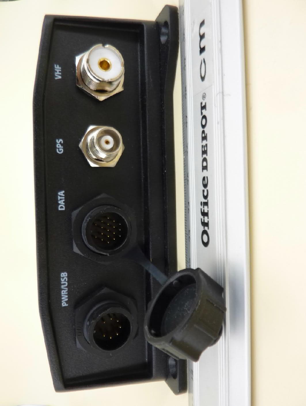
External photographs Examiner:Thomas KÜHNReport Number: F201366E1 Date of issue: 16.11.2020Order Number: 20-111366page 1 of 3 PS200-CS, 3-D-view 1 External photographs Examiner:Thomas KÜHNReport Number: F201366E1 Date of issue: 16.11.2020Order Number: 20-111366page 2 of 3 PS200-CS, 3-D-view 2 External photographs Examiner:Thomas KÜHNReport Number: F201366E1 Date of issue: 16.11.2020Order Number: 20-111366page 3 of 3 PS200-CS, connector view
ID Label/Location Info
AIS Class B CSTDMA Transponder with Chartplotter Label The AIS Class B CSTDMA Transponder with Chartplotter P200-CS unit will be marked with following product label during manufacturing. Each P200-CS unit will have unique production Serial Number. (1) P200-CS Label: (2) Location of Product Label at P200-CS:
Internal Photos
Annex D Internal photographs Examiner:Thomas KÜHNReport Number: F201366E1 Date of issue: 16.11.2020Order Number: 20-111366page 1 of 19 P200-CS, internal view 1 (housing opened) Annex D Internal photographs Examiner:Thomas KÜHNReport Number: F201366E1 Date of issue: 16.11.2020Order Number: 20-111366page 2 of 19 P200-CS, internal view 2 (housing opened) Annex D Internal photographs Examiner:Thomas KÜHNReport Number: F201366E1 Date of issue: 16.11.2020Order Number: 20-111366page 3 of 19 P200-CS, internal view 3 (PCB 1 and 2 removed) Annex D Internal photographs Examiner:Thomas KÜHNReport Number: F201366E1 Date of issue: 16.11.2020Order Number: 20-111366page 4 of 19 P200-CS, internal view 4 (PCB 3 removed) Annex D Internal photographs Examiner:Thomas KÜHNReport Number: F201366E1 Date of issue: 16.11.2020Order Number: 20-111366page 5 of 19 P200-CS, internal view 5 (housing part removed) Annex D Internal photographs Examiner:Thomas KÜHNReport Number: F201366E1 Date of issue: 16.11.2020Order Number: 20-111366page 6 of 19 P200-CS, internal view 6 (cables removed) Photograph supplied by the applicant Annex D Internal photographs Examiner:Thomas KÜHNReport Number: F201366E1 Date of issue: 16.11.2020Order Number: 20-111366page 7 of 19 P200-CS, PCB1, top view Annex D Internal photographs Examiner:Thomas KÜHNReport Number: F201366E1 Date of issue: 16.11.2020Order Number: 20-111366page 8 of 19 P200-CS, PCB1, bottom view Annex D Internal photographs Examiner:Thomas KÜHNReport Number: F201366E1 Date of issue: 16.11.2020Order Number: 20-111366page 9 of 19 P200-CS, PCB2, top view Annex D Internal photographs Examiner:Thomas KÜHNReport Number: F201366E1 Date of issue: 16.11.2020Order Number: 20-111366page 10 of 19 P200-CS, PCB2, bottom view Annex D Internal photographs Examiner:Thomas KÜHNReport Number: F201366E1 Date of issue: 16.11.2020Order Number: 20-111366page 11 of 19 P200-CS, PCB3, top view Annex D Internal photographs Examiner:Thomas KÜHNReport Number: F201366E1 Date of issue: 16.11.2020Order Number: 20-111366page 12 of 19 P200-CS, PCB3, bottom view Annex D Internal photographs Examiner:Thomas KÜHNReport Number: F201366E1 Date of issue: 16.11.2020Order Number: 20-111366page 13 of 19 P200-CS, PCB4, top view Annex D Internal photographs Examiner:Thomas KÜHNReport Number: F201366E1 Date of issue: 16.11.2020Order Number: 20-111366page 14 of 19 P200-CS, PCB4, top view (shielding removed) Annex D Internal photographs Examiner:Thomas KÜHNReport Number: F201366E1 Date of issue: 16.11.2020Order Number: 20-111366page 15 of 19 P200-CS, PCB4, bottom view Annex D Internal photographs Examiner:Thomas KÜHNReport Number: F201366E1 Date of issue: 16.11.2020Order Number: 20-111366page 16 of 19 P200-CS, PCB4, bottom view (shielding removed) Annex D Internal photographs Examiner:Thomas KÜHNReport Number: F201366E1 Date of issue: 16.11.2020Order Number: 20-111366page 17 of 19 P200-CS, PCB5, top view Photograph supplied by the applicant Annex D Internal photographs Examiner:Thomas KÜHNReport Number: F201366E1 Date of issue: 16.11.2020Order Number: 20-111366page 18 of 19 P200-CS, PCB5, bottom view Photograph supplied by the applicant Annex D Internal photographs Examiner:Thomas KÜHNReport Number: F201366E1 Date of issue: 16.11.2020Order Number: 20-111366page 19 of 19 Display unit, rear view Photograph supplied by the applicant
RF Exposure Info
Calculation: RF-Exposure for 156 MHz - 162 MHz transmitter Type identification: P200-CS In accordance to theCFR Part 47, §1.1310and RSS-102 Issue 5 S: Limit for power density according to - CFR Part 47, §1.1310:2.0 W/m 2 - RSS-102 Issue 5, Table 4: 1.291 W/m 2 P:2.51 W (peak value, refer clause 5.5 of test report F201366E1) G: 2.9 dBi = 1.95 (max. antenna gain, declared by the applicant) D: Duty cycle: According to the Recommendation ITU-R M.1371-5 (02/2014) the maximum reporting rate for a Class B AIS is 2 s. So every 2 seconds a 27 ms telegram is transmitted as worst case. This is equal to a duty cycle of 1.35 % = 0.0135. R: Distance in what the limit of S has to be reached: 0.2 m. 푆= 푃⋅퐺⋅퐷 4⋅휋⋅푅 2 ⇒ 푆= 2.51 푊⋅1.95 ⋅0.0135 4⋅휋⋅(0.2 푚) 2 = 0.131 푊 푚 2 The value of the power density is below the limit of CFR Part 47, §1.1310 for the “General population / Uncontrolled Exposure” and below the limit of RSS-102 Issue 5, Table 4 “General Public (uncontrolled environment)”. Base of the above calculations is the highest output power of the EUT.
Test Report
Königswinkel 10 32825 Blomberg, Germany Phone: +49 (0) 52 35 / 95 00-0 Fax:+49 (0) 52 35 / 95 00-10 [email protected] www.phoenix-testlab.de Test Report Report Number: F201366E1 Equipment under Test (EUT): AIS Chart plotter P200-CS Applicant: Alltek Marine Electronics Corporation Manufacturer: Alltek Marine Electronics Corporation Test engineer: Thomas KÜHNReport Number:F201366E1 Date of issue: 16.11.2020Order Number:20-111366page 2 of 24 References [1] ANSI C63.26-2015, American National Standard for Compliance Testing of Transmitters Used in Licensed Radio Services [2] FCC CFR 47 Part 80, Stations In The Maritime Services [3] FCC CFR 47 Part 2,Frequency allocations and radio treaty matters; general rules and regulations [4] RSS-182 Issue 5 January 2012,Maritime Radio Transmitters and Receivers in the Band 156 – 162.5 MHz [5] RSS-Gen Issue 5 March 2019 Amendment 1,General Requirements for Compliance of Radio Apparatus [6] KDB 971168 D01 V03R01 April 2018,Measurement Guidance for Certification of Licensed Digital Transmitters TEST RESULT The requirements of the tests performed as shown in the overview (clause 4) were fulfilled by the equipment under test. The complete test results are presented in the following. This test report is only valid in its original form. Any reproduction of its contents in extracts without written permission of the accredited test laboratory PHOENIX TESTLAB GmbH is prohibited. The test results herein refer only to the tested sample. PHOENIX TESTLAB GmbH is not responsible for any generalisations or conclusions drawn from these test results concerning further samples. Any modification of the tested samples is prohibited and leads to the invalidity of this test report. Each page necessarily contains the PHOENIX TESTLAB Logo and the TEST REPORT NUMBER. Tested and written by: Thomas KÜHN16.11.2020 NameSignatureDate Reviewed and approved by: Bernd STEINER16.11.2020 Name Signature Date Test engineer: Thomas KÜHNReport Number:F201366E1 Date of issue: 16.11.2020Order Number:20-111366page 3 of 24 Contents:Page 1Identification ............................................................................................................................................. 4 1.1Applicant ........................................................................................................................................... 4 1.2Manufacturer .................................................................................................................................... 4 1.3Test laboratory ................................................................................................................................. 4 1.4EUT (Equipment Under Test)........................................................................................................... 5 1.5Technical data of equipment ............................................................................................................ 5 1.6Dates ................................................................................................................................................ 6 2Operational states .................................................................................................................................... 6 3Additional information ............................................................................................................................... 6 4Overview ................................................................................................................................................... 7 5Test results ............................................................................................................................................... 8 5.1Bandwidths ....................................................................................................................................... 8 5.1.1Method of measurement (bandwidths) ..................................................................................... 8 5.1.2Test results (bandwidths) .......................................................................................................... 9 5.2Transmitter frequency tolerances................................................................................................... 10 5.2.1Method of measurement (transmitter frequency tolerances) .................................................. 10 5.2.2Test results (transmitter frequency tolerances) ...................................................................... 11 5.3Spurious emissions on antenna terminals ..................................................................................... 12 5.3.1Method of measurement (spurious emissions on antenna terminals) .................................... 12 5.3.2Test results (spurious emissions on antenna terminals) ........................................................ 13 5.4Modulation characteristics .............................................................................................................. 15 5.4.1Method of measurement (modulation characteristics) ............................................................ 15 5.4.2Test results (modulation characteristics) ................................................................................ 15 5.5Transmitter power .......................................................................................................................... 16 5.5.1Method of measurement (transmitter power) .......................................................................... 16 5.5.2Test results (transmitter power) .............................................................................................. 16 5.6Radiated emissions ........................................................................................................................ 17 5.6.1Method of measurement (radiated emissions) ....................................................................... 17 5.6.2Test r…
Text truncated - open the document above for the full version.
Test Report
Annex A Measurement results Test engineer: Thomas KÜHNReport Number: F201366E1 Date of issue: 16.11.2020Order Number:20-111366page 1 of 21 A.1 26 dB bandwidth 201366_003.wmf: 26 dB bandwidth on 156.025 MHz: 201366_004.wmf: 26 dB bandwidth on 162.025 MHz: A Offset 20 dB LVL Ref 40 dBm Center 156.025 MHzSpan 25 kHz2.5 kHz/ 3DB SWT 280 ms 1 PK MAXH Att 45 dB * RBW 300 Hz VBW 1 kHz -60 -50 -40 -30 -20 -10 0 10 20 30 40 1 Marker 1 [T1 ] 2.39 dBm 156.018930769 MHz 2 Marker 2 [T1 ] 28.50 dB m 156.024700000 MHz 1 Delta 1 [T1 ] -1.46 dB 11.617307692 kHz D1 28.5 dBm D22.5dBm A Offset 20 dB LVL Ref 40 dBm 1 PK MAXH Att 45 dB Center 162.025 MHzSpan 25 kHz2.5 kHz/ * 3DB RBW 300 Hz VBW 1 kHz SWT 280 ms -60 -50 -40 -30 -20 -10 0 10 20 30 40 1 Marker 1 [T1 ] 2.12 dBm 162.019070513 MHz 2 Marker 2 [T1 ] 28.60 dBm 162.024925000 MHz 1 Delta 1 [T1 ] -1.14 dB 11.578525641 kHz D1 28.6 dBm D2 2.6 dBm Annex A Measurement results Test engineer: Thomas KÜHNReport Number: F201366E1 Date of issue: 16.11.2020Order Number:20-111366page 2 of 21 A.2 99 % bandwidth 201366_002.wmf: 99 % bandwidth on 156.025 MHz: 201366_001.wmf: 99 % bandwidth on 162.025 MHz: A Offset 20 dB LVL Ref 40 dBmAtt 25 dB Center 156.025 MHzSpan 25 kHz2.5 kHz/ * 3DB RBW 300 Hz VBW 1 kHz SWT 280 ms 1 PK MAXH -60 -50 -40 -30 -20 -10 0 10 20 30 40 1 Marker 1 [T1 ] 28.62 dBm 156.024700000 MHz OBW 9.700000000 kHz T1 Temp 1 [T1 OBW] 16.51 dBm 156.019950000 MHz T2 Temp 2 [T1 OBW] 15.58 dB m 156.029650000 MHz A Offset 20 dB LVL Ref 40 dBm 1 PK MAXH Center 162.025 MHzSpan 25 kHz2.5 kHz/ Att 25 dB * 3DB RBW 300 Hz VBW 1 kHz SWT 280 ms -60 -50 -40 -30 -20 -10 0 10 20 30 40 1 Marker 1 [T1 ] 33.75 dBm 162.024950000 MHz OBW 9.700000000 kHz T1 Temp 1 [T1 OBW] 17.37 dBm 162.020100000 MHz T2 Temp 2 [T1 OBW] 18.70 dB m 162.029800000 MHz Annex A Measurement results Test engineer: Thomas KÜHNReport Number: F201366E1 Date of issue: 16.11.2020Order Number:20-111366page 3 of 21 A.3 Spectrum Mask 201366_9.wmf: Spectrum mask transmit PRBS on 156.025 MHz: 201366_10.wmf: Spectrum mask transmit PRBS on 162.025 MHz: A Offset 20 dB LVL Ref 33 dBmAtt 40 dB 1 PK MAXH 10 kHz/Center 156.025 MHzSpan 100 kHz * 3DB RBW 300 Hz VBW 1 kHz SWT 1.15 s -60 -50 -40 -30 -20 -10 0 10 20 30 80211F A Offset 20 dB LVL Ref 33 dBmAtt 40 dB 1 PK MAXH 10 kHz/Center 162.025 MHzSpan 100 kHz * 3DB RBW 300 Hz VBW 1 kHz SWT 1.15 s -60 -50 -40 -30 -20 -10 0 10 20 30 80211F Annex A Measurement results Test engineer: Thomas KÜHNReport Number: F201366E1 Date of issue: 16.11.2020Order Number:20-111366page 4 of 21 A.4 Transmitter conducted spurious emissions Transmitter operates on 156.025 MHz 201366_11.wmf: Transmitter conducted spurious emissions from 9 kHz to 150 kHz modulated with PRBS: The emissions around 70 kHz and 140 kHz caused by the measuring system and not by the EUT 201366_12.wmf: Transmitter conducted spurious emissions from 150 kHz to 30 MHz modulated with PRBS: * Offset 20 dB 1 SA MAXH A LVL Ref 33 dBm * 3DB RBW 1 kHz VBW 3 kHz SWT 145 msAtt 25 dB * Start 9 kHzStop 150 kHz14.1 kHz/ -60 -50 -40 -30 -20 -10 0 10 20 30 D1 -13 dBm Ref 33 dBm * * Offset 20 dB 1 SA MAXH A LVL Att 25 dB * 3DB RBW 10 kHz VBW 30 kHz SWT 300 ms Start 150 kHzStop 30 MHz2.985 MHz/ -60 -50 -40 -30 -20 -10 0 10 20 30 D1 -13 dBm Annex A Measurement results Test engineer: Thomas KÜHNReport Number: F201366E1 Date of issue: 16.11.2020Order Number:20-111366page 5 of 21 201366_13.wmf: Transmitter conducted spurious emissions from 30 MHz to 1 GHz modulated with PRBS: 201366_14.wmf: Transmitter conducted spurious emissions from 1 GHz to 2 GHz modulated with PRBS: Ref 33 dBm * * Offset 20 dB A LVL 3DB Att 25 dB RBW 100 kHz VBW 300 kHz SWT 100 ms Start 30 MHzStop 1 GHz97 MHz/ MAXH 1 PK -60 -50 -40 -30 -20 -10 0 10 20 30 D1 -13 dBm Offset 20 dB 1 PK MAXH A LVL * 3DB RBW 1 MHz VBW 3 MHz SWT 10 msAtt 10 dB * Ref 0 dBm Start 1 GHzStop 2 GHz100 MHz/ -100 -90 -80 -70 -60 -50 -40 -30 -20 -10 0 D1 -13 dBm Annex A Measurement results Test engineer: Thomas KÜHNReport Number: F201366E1 Date of issue: 16.11.2020Order Number:20-111366page 6 of 21 Transmitter operates on 162.025 MHz 201366_18.wmf: Transmitter conducted spurious emissions from 9 kHz to 150 kHz modulated with PRBS: The emissions around 70 kHz and 140 kHz caused by the measuring system and not by the EUT 201366_17.wmf: Transmitter conducted spurious emissions from 150 kHz to 30 MHz modulated with PRBS: Ref 33 dBm * Offset 20 dB A LVL Att 25 dB *1 SA MAXH * 3DB RBW 1 kHz VBW 3 kHz SWT 145 ms Start 9 kHzStop 150 kHz14.1 kHz/ -60 -50 -40 -30 -20 -10 0 10 20 30 D1 -13 dBm Ref 33 dBm * Offset 20 dB A LVL Att 25 dB * 3DB RBW 10 kHz VBW 30 kHz SWT 300 ms Start 150 kHzStop 30 MHz2.985 MHz/ *1 SA MAXH -60 -50 -40 -30 -20 -10 0 10 20 30 D1 -13 dBm Annex A Measurement results Test engineer: Thomas KÜHNReport Number: F201366E1 Date of issue: 16.11.2020Order Number:20-111366page 7 of 21 201366_16.wmf: Transmitter conducted spurious emissions from 30 MHz to 1 GHz modulated with PRBS: 201366_15.wmf: Transmitter conducted spurious emissions from 1 GHz to 2 GHz modulated with PRBS: Ref 33 dBm * * Offset 20 dB A LVL 3DB Att 25 dB RBW 100 kHz VBW 300 kHz SWT 100 ms Start 30 MHzStop 1 GHz97 MHz/ MAXH 1 PK -60 -50 -40 -30 -20 -10 0 10 20 30 D1 -13 dBm Offset 20 dB 1 PK MAXH A LVL * 3DB RBW 1 MHz VBW 3 MHz SWT 10 msAtt 10 dB * Ref 0 dBm Start 1 GHzStop 2 GHz100 MHz/ -100 -90 -80 -70 -60 -50 -40 -30 -20 -10 0 D1 -13 dBm Annex A Measurement results Test engineer: Thomas KÜHNReport Number: F201366E1 Date of issue: 16.11.2020Order Number:20-111366page 8 of 21 A.5 Modulation characteristics Transmitter operates on 156.025 MHz 201366_7.wmf: Modulation characteristic modulated with 00001111: 201366_8.wmf: Modulation characteristic modulated with 01010101: Ref 0 Hz * CLRWR A LVL Att 40 dB TRG 1 AP Center 156.025 MHz2.4 ms/ IFB 300 kHz AQT 24 ms -4k -3k -2k -1k 0 1k 2k 3k 4k Ref 0 Hz * CLRWR A LVL Att 40 dB TRG 1 AP Center 156.025 MHz2.4 ms/ IFB 300 kHz AQT 24 ms -4k -3k -2k -1k 0 1k 2k 3k 4k Annex A Measurement res…
Text truncated - open the document above for the full version.
Test Setup Photos
Annex B Test setup photos Examiner: Thomas KÜHNReport Number: F201366E1 Date of issue: 16.11.2020Order Number: 20-111366page 1 of 8 Test setup semi anechoic chamber (position 1) Annex B Test setup photos Examiner: Thomas KÜHNReport Number: F201366E1 Date of issue: 16.11.2020Order Number: 20-111366page 2 of 8 Test setup semi anechoic chamber (position 2) Annex B Test setup photos Examiner: Thomas KÜHNReport Number: F201366E1 Date of issue: 16.11.2020Order Number: 20-111366page 3 of 8 Test setup semi anechoic chamber (position 3) Annex B Test setup photos Examiner: Thomas KÜHNReport Number: F201366E1 Date of issue: 16.11.2020Order Number: 20-111366page 4 of 8 Test setup semi anechoic chamber (30 MHz to 1 GHz) Annex B Test setup photos Examiner: Thomas KÜHNReport Number: F201366E1 Date of issue: 16.11.2020Order Number: 20-111366page 5 of 8 Test setup semi anechoic chamber (1 GHz to 2 GHz) Annex B Test setup photos Examiner: Thomas KÜHNReport Number: F201366E1 Date of issue: 16.11.2020Order Number: 20-111366page 6 of 8 Test setup measurements at antenna port Annex B Test setup photos Examiner: Thomas KÜHNReport Number: F201366E1 Date of issue: 16.11.2020Order Number: 20-111366page 7 of 8 Test setup temperature chamber Annex B Test setup photos Examiner: Thomas KÜHNReport Number: F201366E1 Date of issue: 16.11.2020Order Number: 20-111366page 8 of 8 GPS antenna used for radiated tests
Contact Information
Applicant
Leo Hsieh(QC Specialist)
Test Firm
PHOENIX TESTLAB GmbHHolger Bentje
Technical Specifications
| # | Rule Parts | Frequency Range | Power Output | Emission | Tolerance |
|---|---|---|---|---|---|
| 1 | 80 | 156.025 MHz - 162.025 MHz | 2 W | 16K0F1D | 1.0000000000 ppm |
Other Applications from Alltek Marine Electronics Corporation
WZ7ATON-N321-N323
Jun 30, 2023AIS AtoN (Aids to Navigation)
Equipment Class
AIS - Automatic Identification Systems
WZ7AIS-P200SO
Dec 20, 2020AIS Class B SOTDMA Transponder with Chartplotter
Equipment Class
AIS - Automatic Identification Systems
WZ7AIS-W
Feb 13, 2014AIS Class B Transponder
Equipment Class
AIS - Automatic Identification Systems
WZ7AIS-B108
Feb 12, 2014AIS Class B Transponder
Equipment Class
AIS - Automatic Identification Systems
WZ7SART-500
Jun 04, 2013AIS SART
Equipment Class
GHH - Part 80 VHF Hand Held Transmitter (GMDSS)