WZ7AIS-WAIS Class B Transponder
Alltek Marine Electronics Corporation
Click to zoom
Application Details
- Equipment Class
- AIS - Automatic Identification Systems
- Date of Grant
- Feb 13, 2014
- Application Purpose
- Original Equipment
- Date of Application
- Feb 13, 2014
- Equipment Note
- AIS Class B Transponder
- Frequency Range
- 156.52500000 - 156.52500000
- Country
- Taiwan
Documents & Files
Document Text
Text extracted from the exhibit documents filed with the FCC. Open a document above to read the original.
Users Manual
i COPYRIGHT The entire contents of this instruction manual, including any future updates, revisions, and modifications, shall remain the property of AMEC at all times. Unauthorized copies or reproduction of this manual, either in part or whole, in any form of print and electronic media, is prohibited. The contents herein can only be used for the intended purpose of this manual. DISCLAIMER AMEC is devoted to publish and maintain this product manual. As we continue to improve our AIS products to satisfy all customers’ needs, information in this document is subject to change without notice. AMEC does not make any representations or warranties (implied or otherwise) regarding the accuracy and completeness of this document and shall in no event be liable for any loss of profit or any commercial damage, including but not limited to special, incidental, consequential, or other damage. Manual Revision: Version 1.06 User’s Manual ii WARNING! WARNING: The transponder must be installed and configured in conformity with the provided instructions in the manual in order to maximize the device performance. WARNING: Please bear in mind that not all vessels are equipped with AIS transponders and therefore may not be visible to this transponder. Likewise, certain conditions, such as device malfunction, the environment, improper use, and overcrowded port traffic, may exist whereby the vessel equipped with this AIS transponder is not visible to other AIS transponders. WARNING: DO NOT DISASSEMBLE OR MODIFY THE EQUIPMENT. Improper disassembly or modification could cause personal injury and will invalidate the guarantee. WARNING: While most of the installation can be performed by the owner or the crew, a final commissioning can be done by your local agent/dealer when needed or required. AMEC and the local agent/dealer will not bear any responsibilities over any damages resulted from improper installation by unauthorized agent/dealer. FOR USERS IN THE UNITED STATES OF AMERICA ONLY WARNING: It is a violation of the rules of the Federal Communications Commission to input an MMSI that has not been properly assigned to the end user, or to otherwise input any inaccurate data in this device. ★ The entry of static data into this device shall be performed by the vendor of the device or by an appropriately qualified person in the business of installing marine communications equipment on board vessels. ★ Instructions on how to accurately enter and confirm static data in the device can be found in this user manual. iii FOREWORD AMEC thanks you for the purchase of your new CAMINO-108 Automatic Identification System (hereinafter called “AIS”). Wherever you sail now, you can have a better control of your surrounding sea, and have an enjoyable voyage. CAMINO-108 is strictly tested at the factory to meet the rigorous demands of the marine environment. With proper use, installation, and maintenance, the equipment will serve loyally and reliably at its optimum. For sales, services, and technical supports, please contact your local AMEC representatives or Alltek Marine Electronics Corp at [email protected] or [email protected]. You are always welcome to visit our website at www.alltekmarine.com for new product status and company update. Thank you again. Be safe. iv I TABLE OF CONTENT 1 WHAT IS AIS? ........................................................................ 1 1.1 CLASS A VS. CLASS B AIS ............................................................. 3 1.2 AIS MESSAGE TYPES ................................................................... 4 1.3 AIS REPORT RATE ...................................................................... 4 2 SYSTEM OVERVIEW .............................................................. 5 2.1 PRODUCT DESCRIPTION ............................................................... 5 2.2 EQUIPMENTS IN THE BOX ............................................................. 6 2.3 EXTERNAL CONNECTIONS ............................................................. 7 3 PROGRAMMING YOUR VESSEL DATA .................................... 8 3.1 USB DRIVER INSTALLATION .......................................................... 8 3.2 AIS CONFIGURATION SOFTWARE INSTALLATION ................................ 9 4 INSTALLATION ..................................................................... 10 4.1 INSTALLATION PROCEDURES ........................................................ 10 4.2 MOUNTING TRANSPONDER MAIN UNIT ....................................... 11 4.3 VHF/GPS ANTENNA INSTALLATION ............................................. 13 4.4 GPS ANTENNA LOCATION .......................................................... 14 4.5 CONNECTING POWER AND DATA CABLE ........................................ 15 4.6 CONNECTING WITH NMEA0183 DEVICES .................................... 16 4.7 AIS SILENT MODE CONNECTION ................................................. 20 II 4.8 CONNECTING TO POWER SUPPLY ................................................. 21 4.9 CONNECTION TO NMEA2000 NETWORK ..................................... 21 5 GET STARTED ....................................................................... 22 5.1 START UP THE TRANSPONDER ..................................................... 22 5.2 LED INDICATORS ...................................................................... 23 5.3 SD CARD DATA LOGGING ........................................................... 24 5.4 WI-FI CONFIGURATION (CAMINO-108W ONLY) .......................... 25 5.5 BUILT-IN INTEGRITY TEST (BIIT) .................................................. 26 5.6 AIS VIEWER DESCRIPTION ......................................................... 27 6 SPECIFICATIONS................................................................... 28 6.1 PRODUCT SPECIFICATIONS .......................................................... 28 6.2 DIMENSIONS ........................................................................... 31 6.3 NMEA 2000 PGN INFORMAT…
Text truncated - open the document above for the full version.
Cover Letter(s)
6 2.2 Equipments in the Box Upon receiving the product please verify items in the box. If any is missing, please contact your local AMEC representative immediately.
External Photos
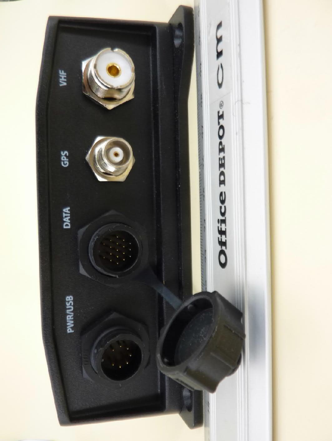
CAMINO-108W External Photos (1)CAMINO-108W external photo #1 (2)CAMINO-108W external photo #2 (3)CAMINO-108W external photo #3 (4)CAMINO-108W external photo #4
ID Label/Location Info
AIS Class B Camino-108, CAMINO-108W Product Label (as of 2013-12-20) The CAMINO-108, CAMINO-108W AIS Class B transponder unit will be marked with following product label during manufacturing. Each CAMINO-108, CAMINO-108W unit will have unique production Serial Number. (1) Product Label: (2) FCC ID label of Wi-Fi module: (3) Location of Product Label: (4) Location of FCC ID label of Wi-Fi module (CAMINO-108W only): 60mm 15mm
Internal Photos
CAMINO-108W Internal Photos (1) CAMINO-108W internal photo #1 (2) CAMINO-108W internal photo #2 (3) CAMINO-108W internal photo #3 (4) CAMINO-108W internal photo #4 (5) CAMINO-108W internal photo #5 (6) CAMINO-108W internal photo #6 (7) CAMINO-108W internal photo #7 (8) CAMINO-108W internal photo #8 (9) CAMINO-108W internal photo #9 (10) CAMINO-108W internal photo #10
Test Report
Report No.: 135096R-SAUSP01V00 Page: 1 of 8 RF Exposure Evaluation declaration Product Name : AIS Class B Transponder Model No. : CAMINO-108, CAMINO-108W FCC ID : WZ7AIS-B108, WZ7AIS-W Applicant : Alltek Marine Electronics Corp. Address : 7F, No.605, Ruei Guang Rd., Neihu, Taipei, Taiwan, 114 R.O.C. Date of Receipt : May 06, 2013 Date of Declaration : Dec. 23, 2013 Report No. : 135096R-SAUSP01V00 Report Version : V1.0 The declaration results relate only to the samples calculated. The declaration shall not be reproduced except in full without the written approval of QuieTek Corporation. Report No.: 135096R-SAUSP01V00 Page: 2 of 8 RF Exposure Evaluation declaration Date of Declaration : Dec. 23, 2013 Report No.: 135096R-SAUSP01V00 Product Name AIS Class B Transponder Applicant Alltek Marine Electronics Corp. Address 7F, No.605, Ruei Guang Rd., Neihu, Taipei, Taiwan, 114 R.O.C. Manufacturer Alltek Marine Electronics Corp. Model No. CAMINO-108, CAMINO-108W Trade Name AMEC Test Result Complied The test report shall not be reproduced except in full without the written approval of Quie Tek Corporation. Documented By : (Adm. Specialist / April Chen) Technical Acceptance By : (Engineer / Paddy Chen) Approved By : (Director / Vincent Lin) Report No. 135096R-SAUSP01V00 Page: 3 of 7 Revision History Rev. Issue Date Revisions Effect page V1.0 December 23, 2013 Initial Issue All Report No. 135096R-SAUSP01V00 Page: 4 of 7 1. GENERAL INFORMATION 1.1. EUT Description Product Name AIS Class B Transponder Trade Name AMEC Model No. CAMINO-108, CAMINO-108W FCC ID. WZ7AIS-B108, WZ7AIS-W Frequency Range WLAN: 2412-2462MHz for 802.11b/g/n-20BW VHF : 156.025MHz~162.025MHz Number of Channels 802.11b/g/n-20MHz: 11 Data Speed WLAN: 802.11b: 1-11Mbps, 802.11g: 6-54Mbps, 802.11n: up to 72.2Mbps VHF : 9600bps/per channel Type of Modulation WLAN: 802.11b:DSSS, DBPSK, DQPSK, CCK 802.11g/n:OFDM, BPSK, QPSK, 16QAM, 64QAM VHF : GMSK/FM Channel Separation WLAN: 802.11b/g/n: 5 MHz VHF : 25KHz Antenna Type Dipole Antenna Gain Refer to the table “Antenna List” Channel Control Auto USB Cable Shielded, 1.8m NMEA2000 Cable Shielded, 3m VHF Cable Shielded, 10m GPS Cable Shielded, 10m Hardware M-PCB-B108MBV1 Software V1.2.6 Antenna List No. Manufacturer Model No. Antenna Type Peak Gain 1 Alltek Marine Electronics Corp. M-ANT-SAA04-05005G-01 Dipole 2 dBi for 2.4 GHz Report No. 135096R-SAUSP01V00 Page: 5 of 7 2. RF Exposure Evaluation 2.1. Limits According to FCC 1.1310: The criteria listed in the following table shall be used to evaluate the environment impact of human exposure to radio frequency (RF) radiation as specified in 1.1307(b). LIMITS FOR MAXIMUM PERMISSIBLE EXPOSURE (MPE) Frequency Range (MHz) Electric Field Strength (V/m) Magnetic Field Strength (A/m) Power Density (mW/cm 2 ) Average Time (Minutes) (A) Limits for Occupational/ Control Exposures 300-1500 -- -- F/300 6 1500-100,000 -- -- 5 6 (B) Limits for General Population/ Uncontrolled Exposures 300-1500 -- -- F/1500 30 1500-100,000 -- -- 1 30 F= Frequency in MHz Friis Formula Friis transmission formula: Pd = (Pout*G)/(4*Pi*R 2 ) Where Pd = power density in mW/cm 2 Pout = output power to antenna in mW G = gain of antenna in linear scale Pi = 3.1416 R = distance between observation point and center of the radiator in cm Pd is the limit of MPE, 1 mW/cm 2 . If we know the maximum gain of the antenna and the total power input to the antenna, through the calculation, we will know the distance r where the MPE limit is reached. 2.2. Test Procedure Software provided by client enabled the EUT to transmit and receive data at lowest, middle and highest channel individually. The temperature and related humidity: 23°Cand 58% RH. Report No. 135096R-SAUSP01V00 Page: 6 of 7 2.3. Test Result of RF Exposure Evaluation Product : AIS Class B Transponder Test Item : RF Exposure Evaluation Test Site : N/A FOR WLAN 802.11b-Peak Gain: 2.0dBi Frequency (MHz) Conducted Power (dBm) Duty Cycle Output Power to Antenna (mW) Power Density at R = 60 cm (mW/cm 2 ) Limit (mW/ cm 2 ) Pass/Fail 2412 15.85 1 38.5 0.0013 1 Pass 2437 15.21 1 33.2 0.0012 1 Pass 2462 14.11 1 25.8 0.0009 1 Pass 802.11g-Peak Gain: 2.0dBi Frequency (MHz) Conducted Power (dBm) Duty Cycle Output Power to Antenna (mW) Power Density at R = 60 cm (mW/cm 2 ) Limit (mW/ cm 2 ) Pass/Fail 2412 22.71 1 186.6 0.0065 1 Pass 2437 22.44 1 175.4 0.0061 1 Pass 2462 21.18 1 131.2 0.0046 1 Pass 802.11n (20M)-Peak Gain: 2.0dBi Frequency (MHz) Conducted Power (dBm) Duty Cycle Output Power to Antenna (mW) Power Density at R = 60 cm (mW/cm 2 ) Limit (mW/ cm 2 ) Pass/Fail 2412 20.89 1 122.7 0.0043 1 Pass 2437 20.64 1 115.9 0.0041 1 Pass 2462 19.48 1 88.7 0.0031 1 Pass Note: The conducted output power is refer to report No.: 135096R-RFUSP42V01 from the QuieTek. FOR VHF Peak Gain: 2.86dBi Frequency (MHz) Conducted Power (dBm) Duty Cycle Output Power to Antenna (mW) Power Density at R = 60 cm (mW/cm 2 ) Limit (mW/ cm 2 ) Pass/Fail 156.025 33.70 1 2344.2 0.1001 0.104 Pass 162.025 33.80 1 2398.8 0.1024 0.108 Pass Note: The conducted output power is refer to report No.: F130840E1 from the PHOENIX. Report No. 135096R-SAUSP01V00 Page: 7 of 7 EXPOSURE FROM SOURCES WITH MULTIPLE FREQUENCES S i is the power density at frequency i; S L is the power density reference level from Table . Both of the WLAN and VHF can transmit simultaneously, the formula of calculated the MPE is : 0.0065/1 + 0.1001/0.104 = 0.969 Therefore, the conclusion data is less than “1”, so compliance with the MPE limit.
Test Report
Königswinkel 10 32825 Blomberg Germany Phone +49 5235 9500 0 Fax +49 5235 9500 10 TEST REPORT on IEC 62287-1 Edition 2 Maritime navigation and radiocommunication equipment and systems Class B shipborne equipment of the automatic identification system (AIS) Part 1: Carrier sense time division multiple access (CSTDMA) techniques Test Report Reference: F130840E1 Equipment under Test: CAMINO-108 / CAMINO-108W Serial Number: - Applicant: Alltek Marine Electronics Corp. Manufacturer: Alltek Marine Electronics Corp. TEST REPORT REFERENCE: F130840E1 Examiner: Raimund BLASK Date of issue: 10 September 2013 page 2 of 43 1 IDENTIFICATION ............................................................................................................................... 3 1.1 APPLICANT ............................................................................................................................... 3 1.2 MANUFACTURER ..................................................................................................................... 3 1.3 DATES ....................................................................................................................................... 3 1.4 TEST LABORATORY ................................................................................................................. 4 1.5 RESERVATION ......................................................................................................................... 4 1.6 REFERENCES........................................................................................................................... 4 2 TECHNICAL DATA OF EQUIPMENT .................................................................................................. 5 3 ADDITIONAL INFORMATION ............................................................................................................. 6 4 TEST OVERVIEW............................................................................................................................... 7 5 TRANSMITTER REQUIREMENTS ..................................................................................................... 8 5.1 FREQUENCY ERROR SUBCLAUSE 11.1.1 ............................................................................ 8 5.2 CARRIER POWER (CONDUCTED) SUBCLAUSE 11.1.2 ......................................................... 9 5.3 MODULATION SPECTRUM SUBCLAUSE 11.1.3 .................................................................... 10 5.4 TRANSMITTER TEST SEQUENCE AND MODULATION ACCURACY SUBCLAUSE 11.1.4 .... 12 5.5 TRANSMITTER OUTPUT POWER VERSUS TIME FUNCTION SUBCLAUSE 11.1.5 ................ 15 6 RECEIVER REQUIREMENTS ............................................................................................................ 17 6.1 TDMA-RECEIVER SENSITIVITY SUBCLAUSE 11.2.1 ............................................................. 17 6.2 ERROR BEHAVIOUR AT HIGH INPUT LEVELS SUBCLAUSE 11.2.2 ..................................... 18 6.3 CO-CHANNEL REJECTION SUBCLAUSE 11.2.3 .................................................................... 19 6.4 ADJACENT CHANNEL SELECTIVITY SUBCLAUSE 11.2.4 ..................................................... 20 6.5 SPURIOUS RESPONSE REJECTION SUBCLAUSE 11.2.5 ..................................................... 21 6.6 INTERMODULATION RESPONSE REJECTION SUBCLAUSE 11.2.6 .................................... 23 6.7 BLOCKING OR DESENSITISATION SUBCLAUSE 11.2.7 ....................................................... 24 6.8 SPURIOUS EMISSIONS FROM THE RECEIVER SUBCLAUSE 11.3.1................................... 26 6.9 SPURIOUS EMISSIONS FROM THE TRANSMITTER SUBCLAUSE 11.3.2 ............................. 29 6.10 MAXIMUM SENSITIVITY SUBCLAUSE C.4 ........................................................................... 35 6.11 ERROR BEHAVIOUR AT HIGH INPUT LEVELS SUBCLAUSE C.4.2 ..................................... 36 6.12 CO-CHANNEL REJECTION SUBCLAUSE C.4.3.................................................................... 37 6.13 ADJACENT CHANNEL SENSITIVITY SUBCLAUSE C.4.4 ..................................................... 38 6.14 SPURIOUS RESPONSE REJECTION SUBCLAUSE C.4.5 .................................................... 39 6.15 INTERMODULATION RESPONSE REJECTION SUBCLAUSE C.4.6 .................................... 40 6.16 BLOCKING OR DESENSITISATION SUBCLAUSE C.4.7 ....................................................... 41 7 TEST EQUIPMENT ............................................................................................................................. 42 8 LIST OF ANNEXES ............................................................................................................................ 43 TEST REPORT REFERENCE: F130840E1 Examiner: Raimund BLASK Date of issue: 10 September 2013 page 3 of 43 1 IDENTIFICATION 1.1 APPLICANT Name: Alltek Marine Electronics Corp. Address: 7F, No. 605, Ruei Guang Rd., Neihu 11492 Taipei Country: Taiwan Name for contact purposes: Mr. Leslie Yang Tel: +886-2-2627-1599 Fax: +886-2-2627-1600 e-mail address: [email protected] 1.2 MANUFACTURER Name: Alltek Marine Electronics Corp. Address: 7F, No. 605, Ruei Guang Rd., Neihu 11492 Taipei Country: Taiwan Name for contact purposes: Mr. Leslie Yang Tel: +886-2-2627-1599 Fax: +886-2-2627-1600 e-mail address: [email protected] 1.3 DATES Date of Receipt of Test Sample: 28 February 2013 Start of test: 28 February 2013 Finish of test: 23 August 2013 TEST REPORT REFERENCE: F130840E1 Examiner: Raimund BLASK Date of issue: 10 September 2013 page 4 of 43 1.4 TEST LABORATORY The tests were carried out at: PHOENIX TESTLAB GmbH Königswinkel 10 D-32825 Blomberg Tel: +49 (0) 52 35 / 95 00-0 Germany Fax: +49 (0) 52 35 / 95 00-10 1.5 RESERVATION This test report is only valid in the original form. Any reproduction of it’s contents without written permission of the accredited test laboratory PHOENIX TEST-LAB GmbH is prohibited. The t…
Text truncated - open the document above for the full version.
Test Report
Annex A: Picture annex to test report F130840E1 EUT: CAMINO-108 / CAMINO-108W Manufacturer: Alltek Marine Electronics Corp. Examiner: Raimund BLASK Date of issue: 10 September 2013 page 1 of 9 130840eut1.jpg: EUT, front-view Annex A: Picture annex to test report F130840E1 EUT: CAMINO-108 / CAMINO-108W Manufacturer: Alltek Marine Electronics Corp. Examiner: Raimund BLASK Date of issue: 10 September 2013 page 2 of 9 130840eut2.jpg: EUT, rear-view Annex A: Picture annex to test report F130840E1 EUT: CAMINO-108 / CAMINO-108W Manufacturer: Alltek Marine Electronics Corp. Examiner: Raimund BLASK Date of issue: 10 September 2013 page 3 of 9 130840eut3.jpg: EUT, inside-view Annex A: Picture annex to test report F130840E1 EUT: CAMINO-108 / CAMINO-108W Manufacturer: Alltek Marine Electronics Corp. Examiner: Raimund BLASK Date of issue: 10 September 2013 page 4 of 9 123924eut4.jpg: Main-PCB, front-view Annex A: Picture annex to test report F130840E1 EUT: CAMINO-108 / CAMINO-108W Manufacturer: Alltek Marine Electronics Corp. Examiner: Raimund BLASK Date of issue: 10 September 2013 page 5 of 9 123924eut5.jpg: M-PCB, front-view Annex A: Picture annex to test report F130840E1 EUT: CAMINO-108 / CAMINO-108W Manufacturer: Alltek Marine Electronics Corp. Examiner: Raimund BLASK Date of issue: 10 September 2013 page 6 of 9 123924eut6.jpg: M-PCB, rear-view Annex A: Picture annex to test report F130840E1 EUT: CAMINO-108 / CAMINO-108W Manufacturer: Alltek Marine Electronics Corp. Examiner: Raimund BLASK Date of issue: 10 September 2013 page 7 of 9 123924eut7.jpg: Main-PCB, front-view Annex A: Picture annex to test report F130840E1 EUT: CAMINO-108 / CAMINO-108W Manufacturer: Alltek Marine Electronics Corp. Examiner: Raimund BLASK Date of issue: 10 September 2013 page 8 of 9 123924eut8.jpg: Main-PCB, front-view Annex A: Picture annex to test report F130840E1 EUT: CAMINO-108 / CAMINO-108W Manufacturer: Alltek Marine Electronics Corp. Examiner: Raimund BLASK Date of issue: 10 September 2013 page 9 of 9 123924eut9.jpg: RF-PCB, rear view
Test Report
Königswinkel 10 32825 Blomberg Germany Phone +49 5235 9500 0 Fax +49 5235 9500 10 TEST REPORT on IEC 62287-1 Edition 2 Sections 10,12,13, Amendment 1 Maritime navigation and radiocommunication equipment and systems Class B shipborne equipment of the automatic identification system (AIS) Part 1: Carrier sense time division multiple access (CSTDMA) techniques Test Report Reference: F130840E2 2 nd Version Equipment under Test: CAMINO-108 / CAMINO-108W Serial Number: - Applicant: Alltek Marine Electronics Corp. Manufacturer: Alltek Marine Electronics Corp. TEST REPORT REFERENCE: F130840E2_2 nd Version Examiner: Raimund BLASK Date of issue: 8 October 2013 page 2 of 73 Contents: Page 1 IDENTIFICATION ........................................................................................................................... 5 1.1 APPLICANT ........................................................................................................................... 5 1.2 MANUFACTURER ................................................................................................................. 5 1.3 DATES ................................................................................................................................... 5 1.4 TEST LABORATORY ............................................................................................................. 5 1.5 RESERVATION ..................................................................................................................... 6 1.6 REFERENCES....................................................................................................................... 6 2 TECHNICAL DATA OF EQUIPMENT .............................................................................................. 7 3 ADDITIONAL INFORMATION ......................................................................................................... 8 4 10 GENERAL INFORMATION ........................................................................................................ 9 4.1 EQUIPMENT HISTORY ......................................................................................................... 9 4.1.1 EUT SYSTEM NO 1 ................................................................................................... 9 4.1.2 EUT SYSTEM NO 2 ................................................................................................... 9 4.2 TEST ENVIRONMENT ........................................................................................................... 9 4.2.1 TEST ENVIRONMENT NO 1 ...................................................................................... 10 4.2.2 TEST ENVIRONMENT NO 2 ...................................................................................... 10 4.3 COMPOSITION...................................................................................................................... 11 4.4 REMARKS ............................................................................................................................. 12 4.5 TEST NOTES ........................................................................................................................ 12 4.5.1 GENERAL PROBLEMS .............................................................................................. 12 5 4. GENERAL REQUIREMENTS ...................................................................................................... 13 5.1 4.2 MANUALS ........................................................................................................................ 13 5.2 MARKING AND IDENTIFICATION ......................................................................................... 14 6 OPERATIONAL TESTS .................................................................................................................. 16 6.1 10.2 MODES OF OPERATING ............................................................................................... 16 6.1.1 10.2.1 AUTONOMOUS MODE ................................................................................... 16 6.1.1.1 10.2.1.1 Transmit Position reports ........................................................................... 16 6.1.1.2 10.2.1.2 Receive Class A position reports ................................................................ 17 6.1.1.3 10.2.1.3 Receive Class B”CS” position reports ......................................................... 18 6.1.1.4 10.2.1.4 Receive in adjacent time periods ................................................................ 19 6.1.1.5 10.2.1.5 Rx performance test ................................................................................... 19 6.1.2 10.2.2 ASSIGNED MODE ........................................................................................... 20 6.1.2.1 10.2.2.1 Group assignment ...................................................................................... 20 6.1.2.2 10.2.2.2 Base station reservations ........................................................................... 23 6.1.3 10.2.3 POLLED MODE/INTERROGATION RESPONSE (SEE 4.1.5.3) ....................... 23 10.2.3.1 Interrogation for Messages 18 and 24 .................................................................... 24 6.1.3.1 10.2.3.2 Interrogation for Message 19 ...................................................................... 25 6.2 10.3 MESSAGES EXTENDING ONE TIME PERIOD .............................................................. 25 TEST REPORT REFERENCE: F130840E2_2 nd Version Examiner: Raimund BLASK Date of issue: 8 October 2013 page 3 of 73 6.3 10.4 CHANNEL SELECTION ................................................................................................. 26 6.3.1 10.4.1 VALID CHANNELS .......................................................................................... 26 6.3.2 10.4.2 INVALID CHANNELS....................................................................................... 26 6.4 10.5 INT…
Text truncated - open the document above for the full version.
Test Report
Annex A: Picture annex to test report F130840E2_2 nd Version EUT: CAMINO-108 / CAMINO-108W Manufacturer: Alltek Marine Electronics Corp. Examiner: Raimund BLASK Date of issue: 8 October 2013 page 1 of 9 130840eut1.jpg: EUT, front-view Annex A: Picture annex to test report F130840E2_2 nd Version EUT: CAMINO-108 / CAMINO-108W Manufacturer: Alltek Marine Electronics Corp. Examiner: Raimund BLASK Date of issue: 8 October 2013 page 2 of 9 130840eut2.jpg: EUT, rear-view Annex A: Picture annex to test report F130840E2_2 nd Version EUT: CAMINO-108 / CAMINO-108W Manufacturer: Alltek Marine Electronics Corp. Examiner: Raimund BLASK Date of issue: 8 October 2013 page 3 of 9 130840eut3.jpg: EUT, inside-view Annex A: Picture annex to test report F130840E2_2 nd Version EUT: CAMINO-108 / CAMINO-108W Manufacturer: Alltek Marine Electronics Corp. Examiner: Raimund BLASK Date of issue: 8 October 2013 page 4 of 9 123924eut4.jpg: Main-PCB, front-view Annex A: Picture annex to test report F130840E2_2 nd Version EUT: CAMINO-108 / CAMINO-108W Manufacturer: Alltek Marine Electronics Corp. Examiner: Raimund BLASK Date of issue: 8 October 2013 page 5 of 9 123924eut5.jpg: M-PCB, front-view Annex A: Picture annex to test report F130840E2_2 nd Version EUT: CAMINO-108 / CAMINO-108W Manufacturer: Alltek Marine Electronics Corp. Examiner: Raimund BLASK Date of issue: 8 October 2013 page 6 of 9 123924eut6.jpg: M-PCB, rear-view Annex A: Picture annex to test report F130840E2_2 nd Version EUT: CAMINO-108 / CAMINO-108W Manufacturer: Alltek Marine Electronics Corp. Examiner: Raimund BLASK Date of issue: 8 October 2013 page 7 of 9 123924eut7.jpg: Main-PCB, front-view Annex A: Picture annex to test report F130840E2_2 nd Version EUT: CAMINO-108 / CAMINO-108W Manufacturer: Alltek Marine Electronics Corp. Examiner: Raimund BLASK Date of issue: 8 October 2013 page 8 of 9 123924eut8.jpg: Main-PCB, front-view Annex A: Picture annex to test report F130840E2_2 nd Version EUT: CAMINO-108 / CAMINO-108W Manufacturer: Alltek Marine Electronics Corp. Examiner: Raimund BLASK Date of issue: 8 October 2013 page 9 of 9 123924eut9.jpg: RF-PCB, rear view
Test Report
Bundesamt für Seeschifffahrt und Hydrographie Federal Maritime and Hydrographic Agency Test Report No. BSH/4542/001/4322516/13Date: 2013-10-01page 2 of 33 Bundesamt für Seeschifffahrt und Hydrographie Federal Maritime and Hydrographic Agency Test Report No. BSH/4542/001/4322516/13Date: 2013-10-01page 3 of 33 General Applicant:Alltek Marine Electronics Corp. 7F, NO.605 Ruei-Guang Rd., Neihu District, Taipei 11492, Taiwan Equipment under test: Type:Camino-108 / Camino-108W Manufacturer: Alltek Marine Electronics Corp. 7F, NO.605 Ruei-Guang Rd., Neihu District, Taipei 11492, Taiwan Place of test:BSH test laboratory Hamburg, Room 916 Start of test:2013-07-08 End of test:2013-08-15 Test standards 1 : IEC 62287-1 Ed.2 (2010) Maritime navigation and radiocommunication equipment and systems- Automatic Identification Systems Class B shipborne equipment of the Universal Automatic Identification System (AIS) using CSTMA techniques IEC 62287-1-am1 ed2.0 (2013) Amendment 1 to IEC 62287-1 Ed.2: Maritime navigation and radiocommunication equipment and systems - Class B shipborne equipment of the automatic identification system (AIS) - Part 1: Carrier-sense time division multiple acces…
Text truncated - open the document above for the full version.
Contact Information
Applicant
Leo Hsieh(QC Specialist)
Test Firm
Phoenix TestLab GmbHH. Altmaier
Technical Specifications
| # | Rule Parts | Frequency Range | Power Output | Emission | Tolerance |
|---|---|---|---|---|---|
| 3 | 8 | 156.525 MHz - 156.525 MHz | 2.35 W | 14K2G2B | 850 Hz |
Other Applications from Alltek Marine Electronics Corporation
WZ7ATON-N321-N323
Jun 30, 2023AIS AtoN (Aids to Navigation)
Equipment Class
AIS - Automatic Identification Systems
WZ7AIS-P200CS
Dec 20, 2020AIS Class B CSTDMA Transponder with Chartplotter
Equipment Class
AIS - Automatic Identification Systems
WZ7AIS-P200SO
Dec 20, 2020AIS Class B SOTDMA Transponder with Chartplotter
Equipment Class
AIS - Automatic Identification Systems
WZ7AIS-B108
Feb 12, 2014AIS Class B Transponder
Equipment Class
AIS - Automatic Identification Systems
WZ7SART-500
Jun 04, 2013AIS SART
Equipment Class
GHH - Part 80 VHF Hand Held Transmitter (GMDSS)