X26BTB-1Bluetooth audio streamer for hearing instruments with wireless capabilities
GN Hearing A/S
Click to zoom
Application Details
- Equipment Class
- DSS - Part 15 Spread Spectrum Transmitter
- Date of Grant
- Jun 10, 2010
- Application Purpose
- Original Equipment
- Date of Application
- Jun 10, 2010
- Equipment Note
- Bluetooth audio streamer for hearing instruments with wireless capabilities
- Frequency Range
- 2404.00000000 - 2478.00000000
- Company
- GN Hearing A/S
- Country
- Denmark
Documents & Files
Document Text
Text extracted from the exhibit documents filed with the FCC. Open a document above to read the original.
Users Manual
1 user guide 23 Statement: This device complies with Part 15 of the FCC rules. Operation is subject to the following two conditions: (1) this de- vice may not cause harmful interference, and (2) this device must accept any interference received, including interference that may cause undesired operation. Note: This equipment has been tested and found to comply with the limits for a Class B digital device, pursuant to part 15 of the FCC rules. These limits are designed to provide reasonable pro- tection against harmful interference in a residential installation. This equipment generates, uses and can radiate radio frequency energy and, if not installed and used in accordance with the instructions, may cause harmful interference to radio communi- cations. However, there is no guarantee that interference will not occur in a particular installation. if this equipment does cause harmful inter- ference to radio or television reception, which can be determined by turning the equipment off and on, the user is encouraged to try to correct the interference by one or more of the following measures: Welcome Congratulations on your purchase of a resound unite Phone Clip. resound unite Phone Clip will allow you to wirelessly connect your resound hearing aids to Bluetooth-enabled mobile phones. This enables clear and hassle-free phone connectivity, whether you are at home, in the office or on the move. Please read this manual carefully to fully benefit from the resound unite Phone Clip. Ask your hearing care professional if you have any questions. For further information you can also check the www.resound.com/unite web site. For your safety, carefully read the chapter Important Information, on pages 24-30 FCC id:X26BTB-1 45 National restrictions: Norway: You are not allowed to operate the equipment within 20 km of the centre of Ny Ålesund. This product is in compliance with the following regulatory stan- dards: in eu: The device conforms to the essential requirements ac- cording to - Annex i of Council directive 93/42/eeC for medical devices (Mdd) and essential requirements and other relevant pro- visions of directive 1999/5/eC (r&TTe). The declaration of con- formity may be consulted at www.resound.com in us: FCC CFr 47 Part 15, subpart C, section 15.247 and 15.249. Other identified applicable international regulatory requirements in countries outside eu and us. Please refer to local country requirements for these areas. The product is categorized as receiver class 2 according to eN 300 440. • Reorient or relocate the receiving antenna • Increase the separation between the equipment and receiver. • Connect the equipment into an outlet on a circuit different from the receiver is connected. • Consult the dealer or an experienced radio/TV technician for help. Changes or modifications can void the user’s authority to operate the equipment. Intended use resound unite Phone Clip is intended to enable resound wire- less hearing instrument users to better follow phone conversa- tions. The essential performance of the resound unite Phone Clip is to transfer signals between a phone with Bluetooth capa- bilities and a resound wireless hearing instrument. List of countries Products are intended for sale in countries within european eco - nomic Area as well as switzerland. 67 Contents description ......................................8-9 getting started....................................10 ON and OFF ......................................12 Bluetooth Pairing...................................13 Basic use ........................................16 Volume Control....................................18 Operating Time....................................18 Wearing Your resound unite Phone Clip................19 Light indicators....................................21 introduction to Bluetooth .........................22-23 important information............................24-30 Technical specifications .............................31 Warranty.........................................32 Troubleshooting guide ...........................34-39 Notes ........................................40 -41 89 5 Multifunctional button 6 Clip 7 Pairing button (behind cover) Description 1 Volume control 2 Mini-usB for charging 3 Led (Light emitting diode) indicator 4 Own voice microphone inlet 5 7 4 1 3 6 2 1011 Pairing to hearing instruments Note! The following information is intended primarily for your hear- ing care professional, who in most cases will complete the tasks that are necessary before the ReSound Unite Phone Clip can be used with your hearing instruments. However, the process is designed to be simple and should be easily accomplished by almost anyone. 1. Make sure resound unite Phone Clip is turned on. Your hear- ing instruments must be off – open the battery door. 2. With the tip of a pen or similar object, press the small pairing button on the back of your resound unite Phone Clip device hidden by the bottom cover (see picture below). Press shortly until the Led indicator turns to solid blue. Your resound unite Phone Clip will remain in pairing mode for 30 seconds. Getting Started Charging the Battery Before using your resound unite Phone Clip, you need to fully charge the rechargeable battery. To charge it, plug the charging cable as shown in the picture be- low. Then plug the other end of the charging cable into a power outlet. during the charging process, the Led indicator will show a solid red light. A solid green light will indi- cate the fully charged status. Charging an empty battery typi- cally takes about 3 hours. it is safe to leave the charger connected overnight – the battery can- not be overcharged. • When charging your ReSound Unite Phone Clip for the first time, leave it to charge for at least 3 hours, even if the battery indicator turns into a solid green light earlier. • For safety reasons, recharge the battery only with chargers supplied by resound. 1213 Bluetooth Pairing if your mobile phone is Bluetooth-e…
Text truncated - open the document above for the full version.
External Photos
Document Title: Doc. #: Rev. #: External photos of BTB-1 0199240 A Form 0007380 - Rev I Short term confidential Page 1 of 3 Corp Template Not subject to issue control when printed Printed Date: 31 May 2010 Lautrupbjerg 7 P.O. Box 130 DK-2750 Ballerup Denmark Owner/Editor: Local Address, if applicable: Jesper Peitersen Date: 31.05.2010 Description according to item number 17168100. Front Top Document Title: Doc. #: Rev. #: External photos of BTB-1 0199240 A Form 0007380 - Rev I Short term confidential Page 2 of 3 Corp Template Not subject to issue control when printed Printed Date: 31 May 2010 Bottom Back Document Title: Doc. #: Rev. #: External photos of BTB-1 0199240 A Form 0007380 - Rev I Short term confidential Page 3 of 3 Corp Template Not subject to issue control when printed Printed Date: 31 May 2010 Left Right
ID Label/Location Info
Xiamen.China This item will be used in electric or electronic equipment. The supplier warrants and represents that the item is, and at all times will be, in compliance with international regulations regarding substances with environmental impact, including but not limited to the RoHS Directive 2002/95 of the European parliament and of the Council. 1,50 2,50 7,00 9,80 19,40 13,00 16,90 1,50 13,00 9,80 4,25 1,80 9,00 BTB BOT COVER, PTD 1737810B Name:Drawing Number:Revision: ¡À1¡ã¡À0.10.1Material:--Checked:ALUSheet:1 of 1Units: mm. Angular:Linear:Symetric:Status:ReleasedDate:21.04.2010Scale:2:1 Unless otherwise specified Design:JZHENGProjectionDRW. size:A4 Rev.CHG.#DescriptionDateDesignChecked B--Release for production21.04.2010JZHENGALU Notes: Pad print color: 1:The color for letters is Grey(Pantone 422 light grey).
Internal Photos
Document Title: Doc. #: Rev. #: Internal photos of BTB-1 0199230 A Form 0007380 - Rev I Short term confidential Page 1 of 1 Corp Template Not subject to issue control when printed Printed Date: 31 May 2010 Lautrupbjerg 7 P.O. Box 130 DK-2750 Ballerup Denmark Owner/Editor: Local Address, if applicable: Jesper Peitersen Date: 31.05.2010 Description according to item number 17181600. Electronics assembly front Electronics assembly back
Test Report
DELTA Venlighedsvej 4 2970 Hørsholm Denmark Tel. +45 72 19 40 00 Fax +45 72 19 40 01 www.delta.dk VAT No. 12275110 DELTA Test Report TEST Reg. no. 19 Th e r e p or t m us t n o t b e r e pr od uc e d, ex c e pt i n f ul l , wi t h o ut t h e wr i tt e n a p pr ov al o f DE L TA . Thi s r e p or t is i s s u e d u nd er t h e r ul es of S W E DA C ( S w e di s h A c c r e di t ati o n) a n d I LA C ( In t er na- ti o n al La b or at or y A c c r e di t ati on Co o p er at i on) i n c l u di n g i ts M RA ( M ut u al Rec o g ni ti o n A r r a n ge- m e nt) . F ur t her i n f or m ati on c an b e f o u n d at w w w.s w e dac.s e a n d ww w .i l ac .or g. Th e r e p or t m us t n o t b e r e pr od uc e d, ex c e pt i n f ul l , wi t h o ut t h e wr i tt e n a p pr ov al o f DE L TA . Thi s r e p or t i s i s s u e d u nd er t h e r ul es of DA N A K ( D ani s h A c c r edi ta ti o n) an d I LA C ( In t er n a ti o n al L ab orat or y A c c r e di t ati o n Co o p er ati on ) i ncl u di ng i ts M RA ( M ut u al Re c o g ni ti on A r r a n gem e nt) . F ur t h er i nf or m ati o n c a n b e fo u n d a t ww w .d a n ak . dk a n d w ww .i l ac . or g. Th e r e p or t m us t n o t b e r e pr od uc e d, ex c e pt i n f ul l , wi t h o ut t h e wr i tt e n a p pr ov al o f DE L TA . EMC_RepGen MAIN TEMPLATE V.47 / 2010-05-17 Radio parameter test of BTB-1 Performed for GN Hearing A/S DANAK-1910912 Projec t no.: A506915-1 Page 1 of 151 3 June 2010 DANAK-1910912 DELTA-A506915-1 Page 2 of 151 JAS/BLJ Title Radio parameter test of BTB-1 Test object BTB-1 Report no. DANAK-1910912 Project no. A506915-1 Test period 19 - 28 May 2010 Client GN Hearing A/S Lautrupbjerg 7 2750 Ballerup Denmark Tel.: +45 45 75 11 11 Contact person Vinnie Nørager E-mail: [email protected] Manufacturer GN Hearing A/S Specifications FCC CFR 47 Part 15, Subpart C IC standard RSS-210, Issue 7:2007 IC standard RSS-Gen, Issue 2:2007 Results The test object was found to be in compliance with the specifications, as listed in Section 1. Test personnel Claus Momme Thomsen Jan Askov Henrik Egeberg Nielsen DANAK-1910912 DELTA-A506915-1 Page 3 of 151 JAS/BLJ Date 3 June 2010 Project Manager Jan Askov Senior Specialist, Wireless DELTA Responsible Claus Rømer Andersen Team Manager, Wireless DELTA DANAK-1910912 DELTA-A506915-1 Page 4 of 151 JAS/BLJ Table of contents Page 1. Summary of tests 5 2. Test objects and auxiliary equipment 7 2.1 Test objects 7 2.2 Auxiliary equipment 8 3. General test conditions 9 3.1 Test setup during test 9 3.2 Radio specifications, receiver and transmitter for WT32 11 3.3 Radio specifications, receiver and transmitter for GN radio 12 3.4 Test sequence 13 4. Test results 14 4.1 Antenna requirement 14 4.2 Measurement of radio frequency voltage on mains 16 4.3 Measurement of radiated emission, receiver, 30 MHz to 1000 MHz 21 4.4 Measurement of radiated emission, receiver, 1 GHz to 25 GHz 24 4.5 Measurement of radiated emission, 0.009 MHz to 30 MHz 26 4.6 Measurement of radiated emission, 30 MHz to 1000 MHz 43 4.7 Measurement of radiated emission, 1 GHz to 25 GHz 80 4.8 Measurement of 20 dB bandwidth and 6 dB bandwidth 105 4.9 Measurement of number of hopping channels 113 4.10 Measurement of carrier frequency separation 117 4.11 Measurement of time of occupancy (Dwell Time) 121 4.12 Measurement of peak output power, conducted 124 4.13 Measurement of spurious RF conducted emissions 132 4.14 Measurement of band-edge compliance of RF conducted emissions 140 4.15 Measurement of power spectral density 146 5. National registrations and accreditations 149 5.1 DANAK Accreditation 149 5.2 FCC Registrations 149 5.3 VCCI Registrations 149 5.4 IC Registrations 150 6. List of instruments 151 DANAK-1910912 DELTA-A506915-1 Page 5 of 151 JAS/BLJ 1. Summary of tests Tests SRD Test methods Rule Section Results Antenna requirement Visual inspection 15.203 Passed Radio frequency voltage on mains ANSI C63.4:2003 15.207 Passed Radiated emission ANSI C63.4:2003 15.209 Passed 20 dB bandwidth DA 00-705 DTS guide:2005 15.247(a)(1) RSS-A8.1(b) Passed Number of hopping channels DA 00-705 DTS guide:2005 15.247(a)(1) RSS-A8.1 Passed Carrier frequency separation DA 00-705 DTS guide:2005 15.247(a)(1) RSS-A8.1 Passed Time of occupancy (Dwell Time) DA 00-705 DTS guide:2005 15.247(a)(1) RSS-A8.1 Passed 6 dB bandwidth DA 00-705 DTS guide:2005 15.247(a)(2) RSS-A8.2(a) Passed Peak output power, conducted DA 00-705 DTS guide:2005 15.247(b)(1) RSS-A8.4 Passed Spurious RF conducted emissions DA 00-705 DTS guide:2005 15.247(d) RSS-A8.5 Passed Band-edge compliance of RF conducted emissions DA 00-705 DTS guide:2005 15.247(d) RSS-A8.5 Passed Power spectral density DTS guide:2005 15.247(e) RSS-A8.2(b) Passed Test Method: DTS guide: 2005. Full name is “Measurement of Digital Transmission Sys-tem operating under section 15.247, March 23, 2005”. Test Method: DA 00-705, Filing and Measurement Guidelines for Frequency Hopping Spread Spectrum System, Released March 30, 2000. The given result is based on a shared risk principle with respect to the measurement un- certainty. DANAK-1910912 DELTA-A506915-1 Page 6 of 151 JAS/BLJ Conclusion The test objects mentioned in this report meet the requirements of the standards stated below. FCC CFR 47 Part 15, Subpart C Specific rule part 15.247 IC Standards: RSS-210 Isusue 7:2007 IC standars RSS-Gen, Issue 2:2007. The test results relate only to the objects tested. DANAK-1910912 DELTA-A506915-1 Page 7 of 151 JAS/BLJ 2. Test objects and auxiliary equipment 2.1 Test objects Test object 2.1.1 Name of test object BTB-1 Model / type BTB-1 Part no. BTB-1 Serial no. B4-13 FCC ID X26BTB-1 Manufacturer GN Hearing A/S Supply voltage 3.3 VDC internal rechargeable battery or external power supply Software version Spurious emission firmware Deltatest: 050510 CSR Bluesuite 3 – Bluetest 3 Cycle time Duty Cycle app. 0.5 ms / 1.0 ms for GN radio Test object 2.1.2 Name of test object BTB-1 Model / type BTB-1 Part no. BTB-1 Serial no. B4-14 FCC I…
Text truncated - open the document above for the full version.
Test Report
1 of 5 Measurement of occupied bandwidth Test method Characteristics IC RSS-Gen:2007, 4.6.1 Temperature: 23ºC. Test voltage: External power supply Test equipm. 49321 49183 49299 Uncertainty: 10 kHz SA Settings RBW: 100 KHz VBW: 300 KHz SPAN: 4 MHz DET: Peak CF: 2402 MHz, 2441 MHz, 2480 MHz and 2404 MHz, 2440 MHz, 2478 MHz Trace: Max Hold Test results Operation frequency Measured Low frequency Measured High frequency Measured 99% emission bandwidth WT-32 module 2402 MHz – GFSK-DH5 2401.393 MHz 2402.626 MHz 1.233 MHz 2441 MHz - GFSK-DH5 2440.389 MHz 2441.631 MHz 1.242 MHz 2480 MHz - GFSK-DH5 2479.398 MHz 2480.637 MHz 1.239 MHz 2402 MHz - π/4-DQPSK-2DH5 2401.244 MHz 2402.753 MHz 1.509 MHz 2441 MHz - π/4-DQPSK-2DH5 2440.254 MHz 2441.749 MHz 1.495 MHz 2480 MHz - π/4-DQPSK-2DH5 2479.276 MHz 2480.765 MHz 1.489 MHz 2402 MHz – 8DQPSK-3DH5 2401.242 MHz 2402.745 MHz 1.503 MHz 2441 MHz - 8DQPSK-3DH5 2440.261 MHz 2441.757 MHz 1.496 MHz 2480 MHz - 8DQPSK-3DH5 2479.284 MHz 2480.762 MHz 1.478 MHz GN Radio 2404 MHz – GFSK 2402.432 MHz 2405.342 MHz 2.910 MHz 2440 MHz – GFSK 2438.594 MHz 2441.395 MHz 2.801 MHz 2478 MHz – GFSK 2476.384 MHz 2479.437 MHz 3.053 MHz Note 1: Band edge criteria 99 % emission bandwidth Test Port Conducted Test mode Continuous Tx - normal modulation - hopping on Comments BTB-1 2 of 5 Comments 2402 MHz – GFSK-DH5 Comments 2441 MHz – GFSK-DH5 Comments 2480 MHz – GFSK-DH5 3 of 5 Comments 2402 MHz – π/4-DQPSK-2DH5 Comments 2441 MHz – π/4-DQPSK-2DH5 Comments 2480 MHz – π/4-DQPSK-2DH5 4 of 5 Comments 2402 MHz – 8DPSK-3DH5 Comments 2441 MHz – 8DPSK-3DH5 Comments 2480 MHz – 8DPSK-3DH5 5 of 5 Comments 2404 MHz – GFSK – GN Radio Comments 2440 MHz – GFSK – GN Radio Comments 2478 MHz – GFSK – GN Radio
Test Setup Photos
DELTA Venlighedsvej 4 2970 Hørsholm Denmark Tel. +45 72 19 40 00 Fax +45 72 19 40 01 www.delta.dk VAT No. 12275110 Version l The report must not be reproduced, except in full, without the written approval of DELTA. Photos Radio parameter test of BTB-1 Performed for GN Hearing AS Page 1 of 14 This exhibit is an extract of DELTA Test Report A506915-1 DANAK-1910912 dated 03 June 2010 containing only the photos of the test set-ups DELTA-A506915-1 Page 2 of 14 JAS/BLJ Photo 4.1.1 Test setup regarding Antenna requirement – Chip antenna. Photo 4.1.2 Test setup regarding Antenna requirement – PCB antenna. DELTA-A506915-1 Page 3 of 14 JAS/BLJ Photo 4.4.1 Test setup regarding measurement of radio frequency voltage on mains. Photo 4.2.2 Test setup regarding measurement of radio frequency voltage on mains. DELTA-A506915-1 Page 4 of 14 JAS/BLJ Photo 4.5.1 Test setup regarding measurement of radiated emission, 0.009 MHz to 30 MHz. Photo 4.5.2 Test setup regarding measurement of radiated emission, 0.009 MHz to 30 MHz. DELTA-A506915-1 Page 5 of 14 JAS/BLJ Photo 4.6.1 Test setup regarding radiated emission, 30 MHz to 1000 MHz. Photo 4.6.2 Test setup regarding radiated emission, 30 MHz to 1000 MHz. DELTA-A506915-1 Page 6 of 14 JAS/BLJ Photo 4.7.1 Test setup regarding measurement of radiated emission, 1 GHz to 25 GHz. Photo 4.7.2 Test setup regarding measurement of radiated emission, 1 GHz to 25 GHz. DELTA-A506915-1 Page 7 of 14 JAS/BLJ Photo 4.8.1 Test setup regarding measurement of 20 dB bandwidth and 6 dB band- width. DELTA-A506915-1 Page 8 of 14 JAS/BLJ Photo 4.9.1 Test setup regarding measurement of number of hopping channels. DELTA-A506915-1 Page 9 of 14 JAS/BLJ Photo 4.10.1 Test setup regarding measurement of carrier frequency separation. DELTA-A506915-1 Page 10 of 14 JAS/BLJ Photo 4.11.1 Test setup regarding measurement of time of occupancy (Dwell Time). DELTA-A506915-1 Page 11 of 14 JAS/BLJ Photo 4.12.1 Test setup regarding measurement of peak output power, conducted. DELTA-A506915-1 Page 12 of 14 JAS/BLJ Photo 4.13.1 Test setup regarding measurement of Spurious RF Conducted Emissions. DELTA-A506915-1 Page 13 of 14 JAS/BLJ Photo 4.14.1 Test setup regarding measurement of band-edge compliance of RF con- ducted emissions. DELTA-A506915-1 Page 14 of 14 JAS/BLJ Photo 4.15.1 Test setup regarding measurement of power spectral density.
Contact Information
Applicant
Nichlas Brown Holm
Technical Contact
Test Firm
DELTA Electronic TestingJorgen Christensen
Technical Specifications
| # | Rule Parts | Frequency Range | Power Output |
|---|---|---|---|
| 2 | 15C | 2.40 GHz - 2.48 GHz | 1.00 mW |
Other Applications from GN Hearing A/S
X26SM-3P
Aug 12, 2024Accesory to wireless hearing instrument
Equipment Class
DTS - Digital Transmission System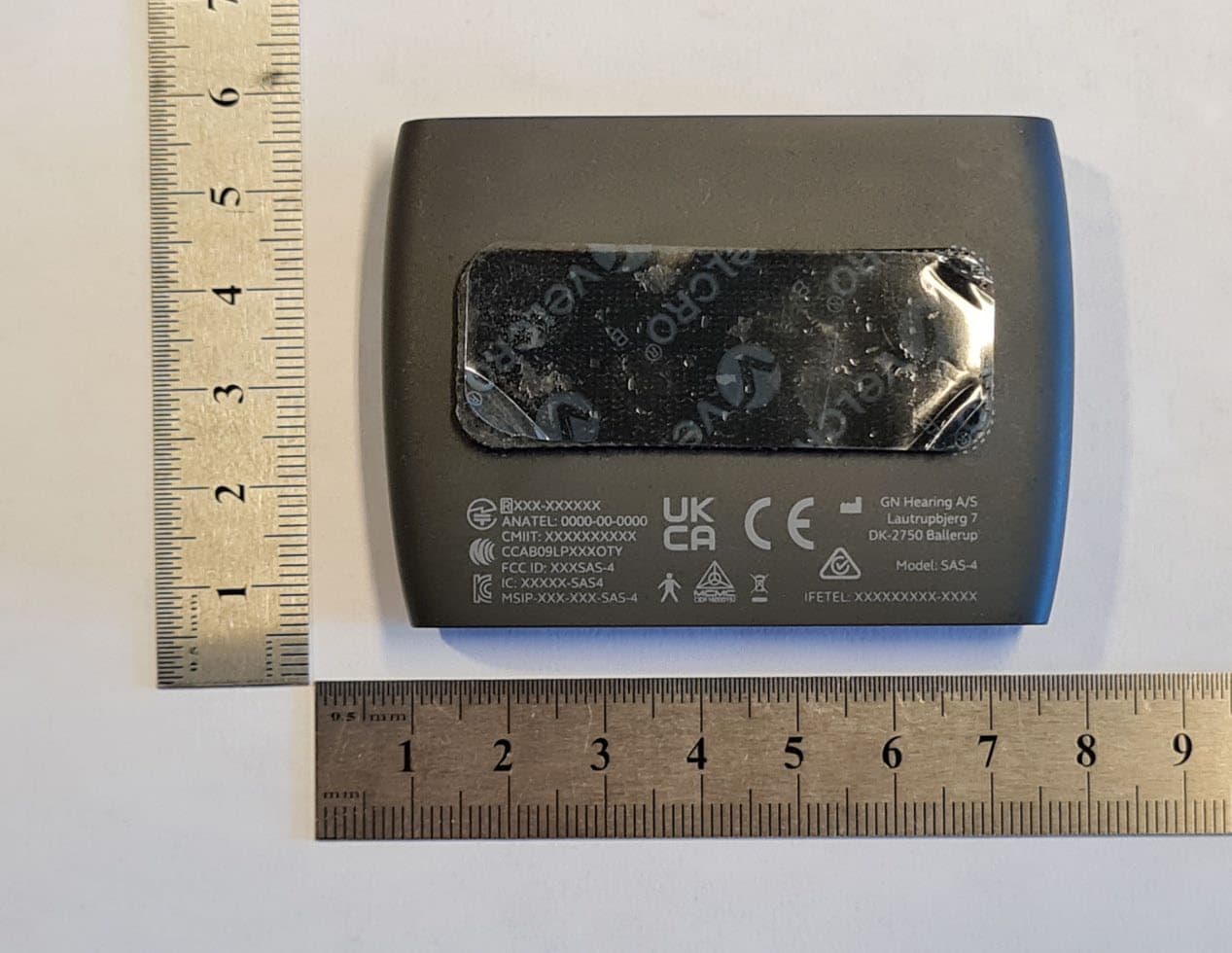
X26SAS-4
Aug 24, 2023Accesory to wireless hearing instrument
Equipment Class
DTS - Digital Transmission System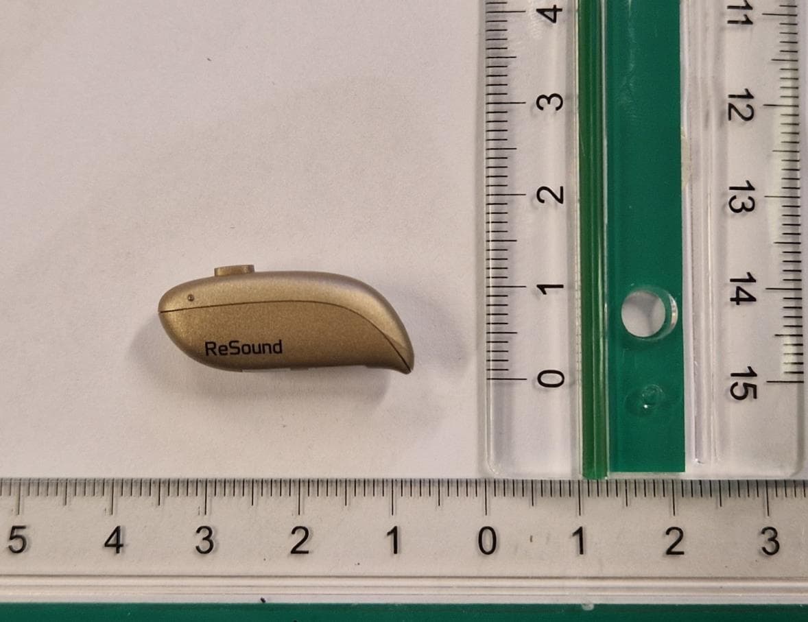
X26DURR1
Jul 10, 2023Rechargeable wireless hearing instrument
Equipment Class
DTS - Digital Transmission System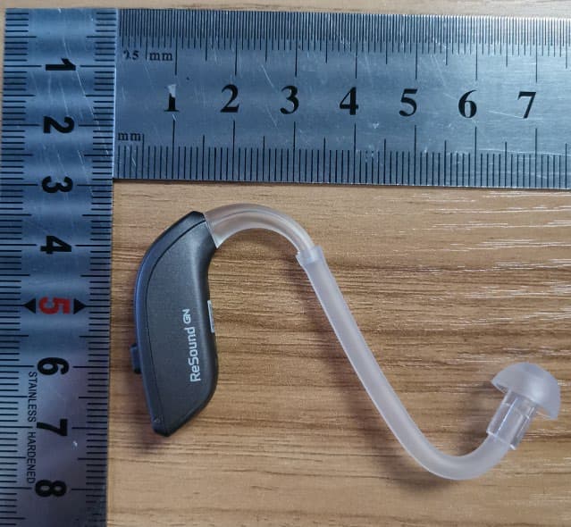
X26CABR70
Feb 21, 2022Wireless hearing instrument
Equipment Class
DXX - Part 15 Low Power Communication Device TransmitterX26WOE46R
Jul 29, 2021Wireless hearing instrument
Equipment Class
DXX - Part 15 Low Power Communication Device Transmitter