X26FD-1Wireless Hearing Instrument
GN Hearing A/S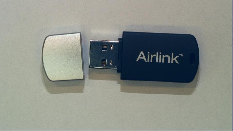
Click to zoom
Application Details
- Equipment Class
- DXT - Part 15 Low Power Transceiver, Rx Verified
- Date of Grant
- Apr 13, 2010
- Application Purpose
- Original Equipment
- Date of Application
- Apr 13, 2010
- Equipment Note
- Wireless Hearing Instrument
- Frequency Range
- 2404.00000000 - 2478.00000000
- Company
- GN Hearing A/S
- Country
- Denmark
Documents & Files
Document Text
Text extracted from the exhibit documents filed with the FCC. Open a document above to read the original.
Users Manual
Airlink installation Airlink is a USB plug and play programming interface enabling you to fit wireless hearing Instruments from ReSound and Beltone. 1) Before you insert the Airlink dongle make sure that you have the correct fitting software installed. The Airlink driver is installed during fitting software in- stallation. • Airlink is supported by ReSound Aventa 3.0 (or later). • Airlink is supported by Beltone Solus Pro 1.0 (or later). 2) After successful installation insert the Airlink dongle into any USB port on your PC or docking station. See illustration below. 3) You are now ready to start fitting wireless ReSound and Beltone products using ReSound Aventa 3 and/ or Beltone Solus Pro 1.0 Compatibility Airlink supports the following operating systems: Windows XP, Windows Vista and Windows 7 • Airlink is compatible with ReSound Aventa 3.0 (or la- ter). Airlink works with all ReSound’s wireless (WL) hearing instrument models released with ReSound Aventa 3.0 or later. • Airlink is compatible with Beltone Solus Pro 1.0 (or later). Airlink works with all Beltone’s wireless (WL) hearing instrument models released with Beltone Solus Pro 1.0 or later. Do not attempt to use Airlink together with any other fitting software unless explicitly instructed. Airlink can co-exist on the same PC together with other hearing instrument programming interfaces (i.e. Speedlink, Hi-PRO, NOAHlink) when using any other fitting software modules. For your safety, carefully read the chapter Important Information. FCC ID: X26FD-1 Statement: This device complies with Part 15 of the FCC rules. Operation is subject to the following two conditions: (1) this device may not cause harmful interference, and (2) this device must accept any interference received, including interference that may cause undesired ope- ration. Note: This equipment has been tested and found to comply with the limits for a Class A digital device, pursuant to part 15 of the FCC Rules. These limits are designed to provide reasonable protection against harmful interference when the equipment is operated in a commercial environment. This equipment gene- rates, uses, and can radiate radio frequency energy and, if not installed and used in accordance with the instruction manual, may cause harmful interference to radio communications. Operation of this equipment in a residential area is likely to cause harmful interference in which case the user will be required to correct the interference at his own expense. Changes or modifications can void the user’s authority to operate the equipment. Intended use The Airlink USB is intended to wirelessly transfer sig- nals from a fitting PC to wireless hearing instruments defined and available in ReSound Aventa 3 and Bel- tone Solus Pro, enabling the fitter to adjust instrument settings wirelessly. List of countries Products are intended for sale in countries within Euro- pean Economic Area as well as Switzerland. In addi- tion products are intended for worldwide sales. These products are intended for worldwide sales, and in compliance with the following regulatory standards: In EU: The device conforms to the Essential Require- ments according to - Annex I of Council Directive 93/42/EEC for medical devices (MDD) - and essential requirements and other relevant provisions of Directive 1999/5/EC (R&TTE). The declaration of conformity may be consulted at www.resound.com. In US: All test objects are subject to FCC Certification according to FCC CFR 47 Part 15, subpart C, section 15.247 For the Norwegian market the accessories comply to EN 12182 Technical Aids for disabled persons. General requirements and test methods covered by EMC and electrical safety tests according to EN/IEC 60601-1-2 and EN/IEC 60950. Other identified applicable international regulatory re- quirements in countries outside EU and US. Please refer to local country requirements for these areas. Products are categorized as receiver class 2 according to Directive 1999/5/EEC on Radio Equipment and Tele- communications Terminal Equipment (R&TTE) Important information Maintenance and care • Cleaning ReSound Airlink is usually not necessary. If needed, use a soft, dry cloth. • Do not attempt to open the device – no serviceable parts inside. If service is required please return the Airlink to your local sales representative or manufac- turer. General warnings • Keep this device out of reach of children under 3 years. • Airlink uses low-powered digitally coded transmis- sions in order to communicate with other wireless devices. Although unlikely, nearby electronic devices may be affected. In that case, move Airlink away from the affected electronic device. • When using Airlink and the device is affected by electromagnetic interference, move away from the source. • Airlink must not be used for any other purpose than for hearing instrument fitting. General precautions • Your hearing instrument and this device were given a unique communication network code during the fitting. This ensures that the device will not affect hearing instruments worn by others. • High-powered electronic equipment, larger electro- nic installations and metallic structures may signifi- cantly reduce the operating range. • Use only original ReSound accessories. • Do not make any changes or modifications to this device. • Do not use Airlink in areas where RF transmission is prohibited, e.g. air planes etc. • Only connect Airlink to connections which it is expli- citly intended for. Technical Specifications Operating range: 3 meters Power supply: Powered by the USB port of a PC Wireless: 2.4 GHz Operating temperature: 0 to 55 degree C Storage temperature: -20 to 70 degree C Temperature test, transport and storage infor- mation The product are subjected to various tests in tempe- rature and damp heating cycling between -25 C and +70C according to internal and industry standards. Warranty The Airlink programming interface is covered by a limited warranty issued by the manufacturer for a p…
Text truncated - open the document above for the full version.
External Photos
Document Title: Doc. #: Rev. #: External photos of FD-1 Airlink 198040 A Form 0007380 - Rev I Short term confidential Page 1 of 3 Corp Template Not subject to issue control when printed Printed Date: 9 April 2010 Lautrupbjerg 7 P.O. Box 130 DK-2750 Ballerup Denmark Owner/Editor: Local Address, if applicable: Jesper Peitersen Date: 07.04.2010 Specifications according to item number 17156800. FRONT BACK Document Title: Doc. #: Rev. #: External photos of FD-1 Airlink 198040 A Form 0007380 - Rev I Short term confidential Page 2 of 3 Corp Template Not subject to issue control when printed Printed Date: 9 April 2010 TOP SIDE BOTTOM SIDE Document Title: Doc. #: Rev. #: External photos of FD-1 Airlink 198040 A Form 0007380 - Rev I Short term confidential Page 3 of 3 Corp Template Not subject to issue control when printed Printed Date: 9 April 2010 RIGHT SIDE LEFT SIDE
Internal Photos
Document Title: Doc. #: Rev. #: Internal photos of FD-1 Airlink 198010 A Form 0007380 - Rev I Short term confidential Page 1 of 1 Corp Template Not subject to issue control when printed Printed Date: 8 April 2010 Lautrupbjerg 7 P.O. Box 130 DK-2750 Ballerup Denmark Owner/Editor: Local Address, if applicable: Jesper Peitersen Date: 07.04.2010 Description according to item number 17157200. FRONT BACK
Test Report
DELTA Venlighedsvej 4 2970 Hørsholm Denmark Tel. +45 72 19 40 00 Fax +45 72 19 40 01 www.delta.dk VAT No. 12275110 DELTA Test Report TEST Reg. no. 19 The report must not be reproduced, except in full, without the written approval of DELTA. This report is issued under the rules of SWEDAC (Swedish Accreditation) and ILAC (Interna- tional Laboratory Accreditation Cooperation) including its MRA (Mutual Recognition Arrange- ment). Further information can be found at www.swedac.se and www.ilac.org. The report must not be reproduced, except in full, without the written approval of DELTA. This report is issued under the rules of DANAK (Danish Accreditation) and ILAC (International Laboratory Accreditation Cooperation) including its MRA (Mutual Recognition Arrangement). Further information can be found at www.danak.dk and www.ilac.org. The report must not be reproduced, except in full, without the written approval of DELTA. EMC_RepGen MAIN TEMPLATE V.45 / 2010-03-08 Radio parameter test of FD-1 Performed for GN Hearing A/S DANAK-1910854, Rev. B Project no.: A506404-2 Page 1 of 50 14 April 2010 DANAK-1910854, Rev. B DELTA-A506404-2 Page 2 of 50 JAS/BLJ Title Radio parameter test of FD-1 Test object FD-1 Report no. DANAK-1910854, Rev. B Project no. A506404-2 Test period 6 November 2009 to 13 April 2010 Client GN Hearing A/S Lautrupbjerg 7 2750 Ballerup Denmark Tel.: +45 45 75 11 11 Contact person Vinnie Nørager E-mail: [email protected] Manufacturer GN Hearing A/S Specifications FCC CFR 47 Part 15, Subpart C Results The test objects were found to be in compliance with the specifications, as listed in Section 1 Test personnel Claus Momme Thomsen Henrik Egebjerg Nielsen Jan Askov DANAK-1910854, Rev. B DELTA-A506404-2 Page 3 of 50 JAS/BLJ Date 14 April 2010 Project Manager Jan Askov Senior Specialist, Wireless DELTA Responsible Claus Rømer Andersen Team Manager, Wireless DELTA This report is a revision of the test report A506404-2 Rev. A dated 14 April 2010. The revision has been made due to the following: Units corrected on page 34, 36 and 38 (dBμV changed to dBμV/m). Instrument list revised to include calibration date and calibration interval. DANAK-1910854, Rev. B DELTA-A506404-2 Page 4 of 50 JAS/BLJ Table of contents Page 1. Summary of tests 5 2. Test objects 6 2.1 Test objects 6 3. General test conditions 8 3.1 Test setup during test 8 3.2 Description of radio link 9 3.3 Test sequence 10 4. Test results 11 4.1 Peak to Average Correction Factor (PACF) 11 4.2 Antenna requirement 13 4.3 Measurement of radio frequency voltage on mains 15 4.4 Measurement of radiated emission, 0.009-30 MHz 18 4.5 Measurement of radiated emission, 30 MHz to 1000 MHz 23 4.6 Measurement of radiated emission, 1 GHz to 25 GHz 33 4.7 Measurement of band edge compliance 40 4.8 Measurement of field strength of fundamental 44 5. National registrations and accreditations 48 5.1 DANAK Accreditation 48 5.2 FCC Registrations 48 5.3 VCCI Registrations 49 5.4 IC Registrations 49 6. List of instruments 50 DANAK-1910854, Rev. B DELTA-A506404-2 Page 5 of 50 JAS/BLJ 1. Summary of tests Tests Test methods Rule Section Results Peak to Average Correction Factor (PACF) 15.35(c) N.A. Antenna requirement Visual inspection 15.203 Passed Measurement of radio frequency voltage on mains ANSI C63.4:200315.207 Passed Measurements of radiated emission ANSI C63.4:200315.209 Passed Measurement of band edge compliance ANSI C63.4:2003 15.215(c) Passed Measurement of field strength of funda- mental ANSI C63.4:200315.249 Passed The given result is based on a shared risk principle with respect to the measurement un- certainty. Conclusion The test objects mentioned in this report meet the requirements of the standard stated be- low. FCC CFR 47 Part 15, Subpart C Specific rule part 15.249. The test results relate only to the objects tested. DANAK-1910854, Rev. B DELTA-A506404-2 Page 6 of 50 JAS/BLJ 2. Test objects 2.1 Test objects Test object 2.1.1 Name of test object FD-1 Model / type FD-1 Part no. FD-001 Serial no. EMC 3-Spurius Emissions FCC ID X26FD-1 Manufacturer GN Hearing A/S Supply voltage USB power supply Software version Special firmware for spurious emission test Ver- sion:0D Cycle time 0.5 ms / 1.0 ms Comments Supplied by external power supply Test object 2.1.2 Name of test object FD-1 Model / type FD-1 Part no. FD-002 Serial no. EMC 3-Conducted FCC ID X26FD-1 Manufacturer GN Hearing A/S Supply voltage USB power supply Software version Special firmware for Spurious emission test Version:0D Cycle time 0.5 ms / 1.0 ms Comments Antenna replaced by SMA connector and supplied by external power supply DANAK-1910854, Rev. B DELTA-A506404-2 Page 7 of 50 JAS/BLJ Auxiliary equipment 2.1.3 Name of auxiliary equipment PC Laptop Model / type ThinkPad T43 Part no. 2669-CTO Serial no. L3-KTDP6 FCC ID - Manufacturer IBM Supply voltage 220 V via adaptor for Test PC Comments Test PC - USB power for FD-1 Auxiliary equipment supplied by the client DANAK-1910854, Rev. B DELTA-A506404-2 Page 8 of 50 JAS/BLJ 3. General test conditions 3.1 Test setup during test Figure 3.1.1 Block diagram of test object and auxiliary equipment. All test objects were running special test software. During test, the test objects were in continuous TX mode. (Normal modulation, normal data packets with optimized repetition rate) Tests were performed at three frequencies Low frequency: 2404 MHz Middle frequency: 2441 MHz High frequency: 2478 MHz. During relevant tests, the test PC was replaced by an external DC power supply. Intended use FD-1 is used to fit or configure hearing aids to the hearing aid user. It is intended to be used at hearing clinics only, i.e. it is not intended for connection to a Class B personal computer. FD-1 is a Class A device. Size of the test object The test object measures 45 x 20 x 10 mm. 3 m USB cable Test object FD-1 Radio link AC mains AUX PC DANAK-1910854, Rev. B DELTA-A506404-2 Page 9 of 50 JAS/BLJ 3.2 Description of radio link The radio of the te…
Text truncated - open the document above for the full version.
Test Setup Photos
DELTA Venlighedsvej 4 2970 Hørsholm Denmark Tel. +45 72 19 40 00 Fax +45 72 19 40 01 www.delta.dk VAT No. 12275110 Version l The report must not be reproduced, except in full, without the written approval of DELTA. Photos Radio parameter test of FD-1 Performed for GN Hearing A/S Page 1 of 9 This exhibit is an extract of DELTA Test Report A506404-2, Rev. A DANAK-1910854 dated 13 April 2010 containing only the photos of the test set-ups DELTA-A506404-2 Page 2 of 9 JAS/BLJ Photo 4.2.1 Test setup regarding measurement of antenna requirement. Photo 4.2.2 Test setup regarding measurement of antenna requirement. PCB antenna DELTA-A506404-2 Page 3 of 9 JAS/BLJ Photo 4.3.1 Test setup regarding measurement of radio frequency voltage on mains. Photo 4.3.2 Test setup regarding measurement of radio frequency voltage on mains. DELTA-A506404-2 Page 4 of 9 JAS/BLJ Photo Error! No text of specified style in document..1 Test setup regarding measure- ment of radiated emission, 0.009-30 MHz. Photo Error! No text of specified style in document..2 Test setup regarding measure- ment of radiated emission, 0.009-30 MHz. DELTA-A506404-2 Page 5 of 9 JAS/BLJ Photo Error! No text of specified style in document..3 Test setup regarding meas- urement of radiated emission, 0.009-30 MHz. Photo Error! No text of specified style in document..4 Test setup regarding meas- urement of radiated emission, 0.009-30 MHz. DELTA-A506404-2 Page 6 of 9 JAS/BLJ Photo 4.5.1 Test setup regarding measurement of radiated emission. Photo 4.5.2 Test setup regarding measurement of radiated emission. DELTA-A506404-2 Page 7 of 9 JAS/BLJ Photo 4.6.1 Test setup regarding measurement of radiated emission. Photo 4.6.2 Test setup regarding measurement of radiated emission. DELTA-A506404-2 Page 8 of 9 JAS/BLJ Photo 4.7.1 Test setup regarding measurement of band edge compliance. Photo 4.7.2 Test setup regarding measurement of band edge compliance. DELTA-A506404-2 Page 9 of 9 JAS/BLJ Photo 4.8.1 Test setup regarding measurement of field strength of fundamental. Photo 4.8.2 Test setup regarding measurement of field strength of fundamental.
Contact Information
Applicant
Nichlas Brown Holm
Test Firm
DELTA Electronic TestingJorgen Christensen
Technical Specifications
| # | Rule Parts | Frequency Range | Power Output |
|---|---|---|---|
| 1 | 15C | 2.40 GHz - 2.48 GHz | - |
Other Applications from GN Hearing A/S
X26SM-3P
Aug 12, 2024Accesory to wireless hearing instrument
Equipment Class
DTS - Digital Transmission System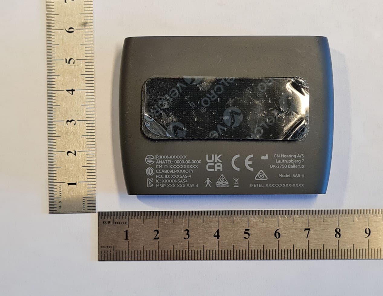
X26SAS-4
Aug 24, 2023Accesory to wireless hearing instrument
Equipment Class
DTS - Digital Transmission System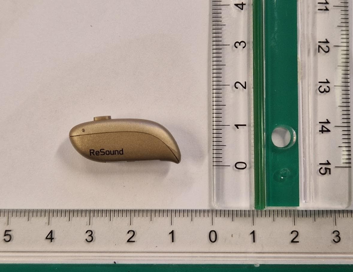
X26DURR1
Jul 10, 2023Rechargeable wireless hearing instrument
Equipment Class
DTS - Digital Transmission System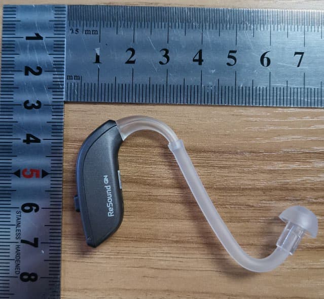
X26CABR70
Feb 21, 2022Wireless hearing instrument
Equipment Class
DXX - Part 15 Low Power Communication Device TransmitterX26WOE46R
Jul 29, 2021Wireless hearing instrument
Equipment Class
DXX - Part 15 Low Power Communication Device Transmitter