X280065Evoke F4
Imagination Technologies Ltd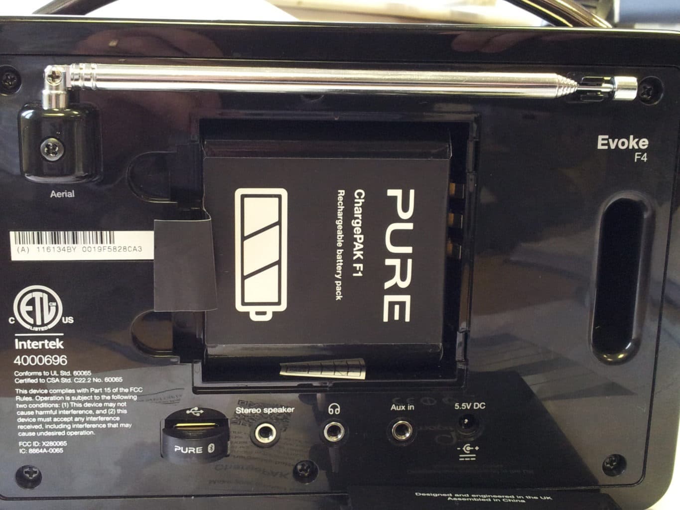
Click to zoom
Application Details
- Equipment Class
- DTS - Digital Transmission System
- Date of Grant
- Feb 02, 2014
- Application Purpose
- Original Equipment
- Date of Application
- Jan 30, 2014
- Equipment Note
- Evoke F4
- Frequency Range
- 2412.00000000 - 2462.00000000
- Company
- Imagination Technologies Ltd
- Country
- United Kingdom
Documents & Files
Document Text
Text extracted from the exhibit documents filed with the FCC. Open a document above to read the original.
Users Manual
Evoke F4 with Bluetooth 1 ES ENGLISH FR Thank you for choosing Evoke F4 with Bluetooth. This wireless music and radio system brings a world of listening simply and easily within your reach. You can use it to enjoy music streamed wirelessly from your iOS or Android device or from your PC or Mac; to listen to any Internet or FM radio station; and to play thousands of podcasts, on-demand radio programs and evocative ambient sounds. You can also access the Pure Connect cloud-based on-demand subscription streaming service to gain instant access to millions of music tracks. This manual will get you up and running in no time, and explains how to make the most of your Evoke F4. We’re constantly improving and adding new features to our products. To take advantage of any enhancements made since your product was shipped, please visit support.pure.com/us where you can download the latest version of this user guide in PDF format. SelectVolume Evoke F4 with Bluetooth 2 Important Safety Instructions 1. Read these instructions – All the safety and operating instructions should be read before this product is operated. 2. Keep these instructions – The safety and operating instructions should be retained for future reference. 3. Heed all warnings – All warnings on the appliance and in the operating instructions should be adhered to. 4. Follow all instructions – All operating and use instructions should be followed. 5. Do not use this apparatus near water. 6. Clean only with dry cloth. 7. Do not block any ventilation openings. Install in accordance with the manufacturer’s instructions. 8. Do not install near any heat sources such as radiators, stoves, or other apparatus that produce heat. 9. Only use attachments and accessories specified by the manufacturer. 10. Unplug the apparatus during lightning storms or when unused for long periods of time. 11. Do not use the mains adapter outdoors. 12. Be aware of volume levels when using headphones, excessive volume can damage your hearing. 13. Cease use immediately if apparatus exhibits any signs of mechanical damage, excessive temperature, swelling or splitting. 14. Refer all servicing to qualified service personnel. Servicing is required when the apparatus has been damaged in any way, such as power-supply cord or plug is damaged, liquid has been spilled or objects have fallen into the apparatus, the apparatus has been exposed to rain or moisture, does not operate normally, or has been dropped. 15. To reduce the risk of electric shock, do not remove cover (or back) as there are no user-serviceable parts inside. Refer servicing to qualified personnel. 16. Use only power supplies listed in the user instructions (with model no. DSA-24CA-05 055357, manufactured Pure). 17. Servicing is required when the apparatus has been damaged in any way, such as power supply cord or plug is damaged, or the apparatus does not operate normally, or has been dropped. 18. WARNING To reduce the risk of fire or electric shock, do not expose this apparatus to rain or moisture. The apparatus shall not be exposed to dripping or splashing and that objects filled with liquids, such as vases, shall not be placed on apparatus. 19. CAUTION: Danger of explosion if battery is incorrectly replaced. Replace only with the same or equivalent type. 20. WARNING: The direct plug-in adapter is used as disconnect device, the disconnect device shall remain readily operable. 21. This equipment is a Class II or double insulated electrical appliance. It has been designed in such a way that it does not require a safety connection to electrical earth. Damage to hearing can occur with consistent exposure to high volume when using headphones. Always check the volume level before inserting headphones into your ears. Use of headphones while operating a vehicle is not recommended and is illegal in some areas. Stop listening to your radio if you find it distracting while operating any type of vehicle or performing any other activity that requires your full attention. 3 EN Contents 4 Getting started 4 Quick start 5 Controls and sensors 6 Rear panel 6 Switching between Sleep, Standby and On 7 Screen icons 8 Internet listening via Pure Connect 8 Listening to Internet radio 9 Listening to other Internet content 10 Music streaming 10 Pure Connect tagging service 11 SiriusXM 12 Streaming from the Pure Connect app 12 Download the Pure Connect app 12 Selecting Evoke or other Pure Jongo compatible device in the Pure Connect app 13 Streaming music from a PC or Mac 13 Listening to streamed tracks on Evoke 13 Listening to FM radio 13 Changing FM stations 13 Storing a preset 13 Listening to a preset 14 Listening to audio from a USB memory stick 14 Using Bluetooth 15 Recording radio programs 15 Instant recordings 15 Timed recordings 16 Setting alarms and timers 16 Setting an alarm 16 Setting the sleep timer 16 Setting the kitchen timer 16 Cancelling a sounding alarm or timer 16 Snoozing a sounding alarm 16 Changing the alarm snooze time 16 Cancelling a snoozing alarm 17 Options and settings 17 Pure Connect settings 17 FM settings 17 Network/USB media 18 Audio settings 19 Setting the clock 19 Changing the language shown on the display 19 Changing Evoke’s name 19 Bluetooth settings 20 Upgrading Evoke 20 Resetting Evoke to factory settings 21 Network settings 22 Using an optional ChargePAK F1 22 Installing a ChargePAK 23 Help and advice 24 Specifications 4 Extend the aerial and insert the connector of the supplied power adapter into the 5.5V DC input on the rear of Evoke. Plug the adapter into the power supply. Pure is displayed briefly on-screen. Getting started Quick start Note: If you have a ChargePAK F1 rechargeable battery (sold separately) fit it now before plugging in Evoke. See page 22 for more information. Choose your display language (English, French or Spanish) by turning the Select dial to highlight the language you want. Push the Select dial in to confirm your choice. Repeat this process to select the time zone and region …
Text truncated - open the document above for the full version.
Cover Letter(s)
Request for Confidentiality Date:25 th April 2013 Subject: Confidentiality Request for:X280065_ Pursuant to FCC 47 CRF 0.457(d) and 0.459 and IC RSP-100, Section 10, the applicant requests that a part of the subject FCC application be held confidential. Type of Confidentiality RequestedExhibit Short TermPermanentBlock Diagrams Short TermExternal Photos Short TermPermanent* 1 Internal Photos Short TermPermanentOperation Description/Theory of Operation Short TermPermanentParts List & Placement/BOM Short TermPermanentTune-Up Procedure Short TermPermanentSchematics Short TermTest Setup Photos Short TermPermanent*User’s Manual *Note: ______(Insert Explanation as Necessary)______ Imagination Technologies Ltd / Pure has spent substantial effort in developing this product and it is one of the first of its kind in industry. Having the subject information easily available to "competition" would negate the advantage they have achieved by developing this product. Not protecting the details of the design will result in financial hardship. Permanent Confidentiality: The applicant requests the exhibits listed above as permanently confidential be permanently withheld from public review due to materials that contain trade secrets and proprietary information not customarily released to the public. Short-Term Confidentiality: Not Applicable NOTE for Industry Canada Applications: The applicant understands that until such time that IC distinguishes between Short Term and Permanent Confidentiality, either type of marked exhibit above will simply be marked Confidential when submitted to IC. Sincerely, By:_____JASON MILLER_______
Cover Letter(s)
Authority to Act as Agent Date: 25 th April 2013 American Certification Body, Inc. 6731 Whittier Avenue Suite C110 McLean, VA 22101 To Whom It May Concern: RN Electronics Ltd is authorized to act on our behalf, until otherwise notified, for applications to American Certification Body, Inc. (ACB). We certify that we are not subject to denial of federal benefits, that includes FCC benefits, pursuant to Section 5301 of the Anti-Drug Abuse Act of 1988, 21 U.S.C. 862. Further, no party, as defined in 47 CFR 1.2002 (b),to the application is subject to denial of federal benefits, that includes FCC benefits. Thank you, Agency Agreement Expiration Date: 25 th April 2015 By:____ JASON MILLER_____ Title:__Quality Manager______ On behalf of: Imagination Technologies Ltd / Pure Division Telephone:+44 1923 622252
External Photos
Pure Evoke F4 External Pictures Front and rear views With battery door removed ..and battery fitted
ID Label/Location Info
Name EVOKE F440 rear silkscreen Part # 14V01 Version V7 Date 01/03/2013 Pantone Silver 877C
Internal Photos
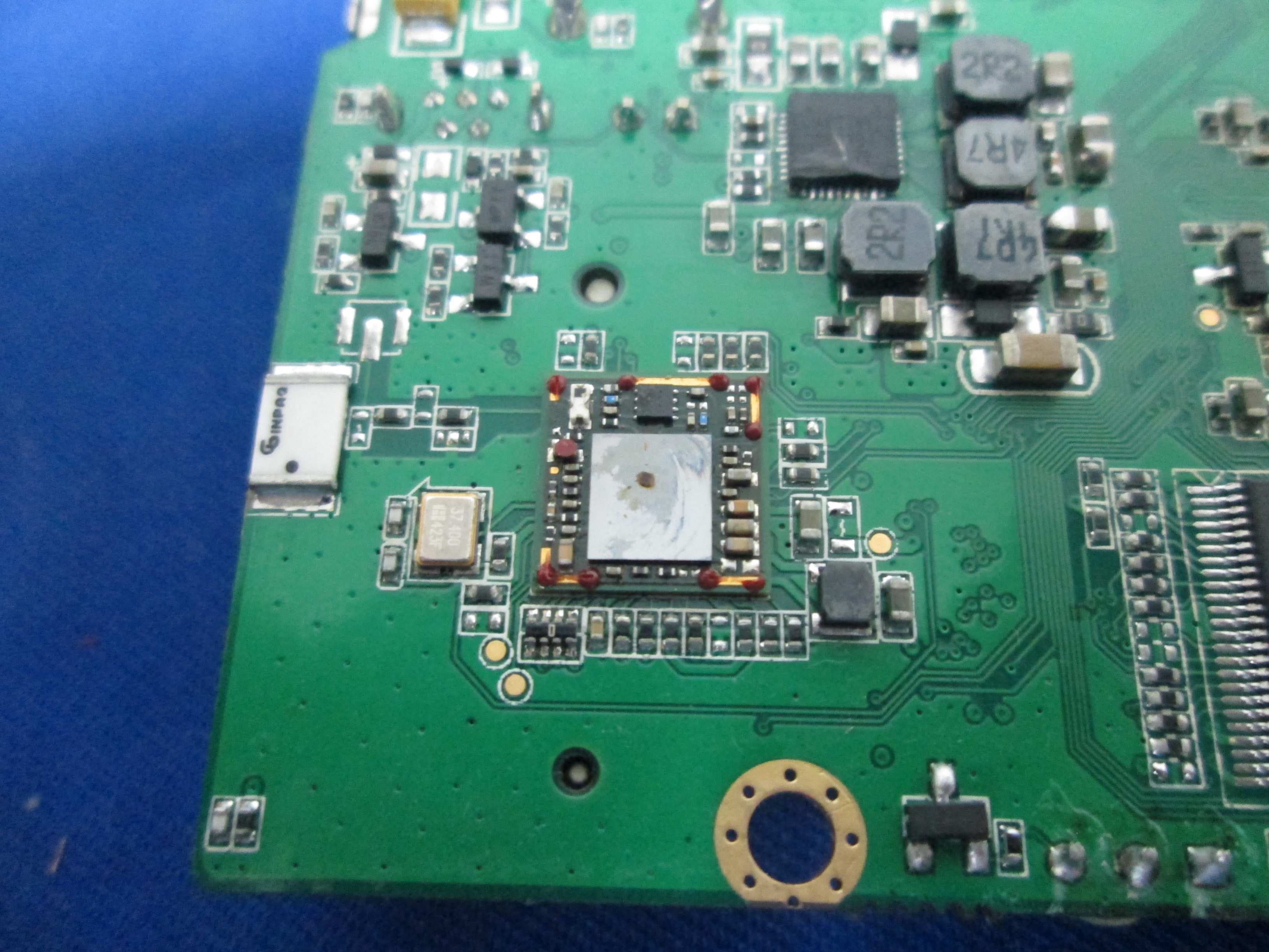
Pure Evoke F4 – internal photos Rear cover opened. View showing radio module in carrier PCB and WiFi antenna PCB fixed to ground plane. Picture below showing connections to connector PCB and encoder PCB Rear moulding and PCBs removed from cabinet Carrier PCB with radio module removed Top side of carrier after removal from rear moulding. Carrier PCB with screening can lid removed Radio module with cans fitted Radio module with screening cans removed Bottom view of radio module with screening cans Bottom view of radio module with screening cans removed Rear connector PCB Battery contact PCB WiFi antenna PCB fixed to ground plane Cabinet with rear panel removed showing encoder PCB and connection to cap sense PCB Snooze handle PCB with cable routing across top of cabinet Cap sense PCB on front moulding with facia removed ..and cap sense PCB removed from moulding
RF Exposure Info
Evoke 440DR RF Exposure:- The Evoke 440DR is intended as a mobile device. A warning statement is included in the user manual advising users to maintain a minimum distance of 20cm. Evaluation is therefore for exposure potential against the MPE limits given in Appendix A of OET Bulletin 65, Supplement C: 1500-100,000MHz; 1mW/cm 2 Compliance requirements are based upon General population / Uncontrolled exposure. Equation (3) of OET Bulletin 65: where: S = power density (in appropriate units, e.g. mW/cm 2 ) P = power input to the antenna (in appropriate units, e.g. mW) G = power gain of the antenna in the direction of interest relative to an isotropic radiator R = distance to the centre of radiation of the antenna (appropriate units, e.g. cm) Substituting known values for the Evoke F4: WiFi RF worst case AV power, P = 45.7mW (+16.6dBm). WiFi antenna gain (measured), G = 0.8 dB. n.b. although the specified gain for the chip antenna is 0dBi, this is the best gain (Mid channel gain) measured in practice. Distance, R = 20cm (for mobile use). S = 0.011< 1mW/cm 2 The Evoke 440DR may also be fitted with a pre-approved FCC Bluetooth USB dongle to its external USB port, which would therefore be co-located. Maximum power of all Bluetooth devices is 100mW eirp. The maximum MPE is therefore as follows. Equation (3) of OET Bulletin 65: where: S = power density (in appropriate units, e.g. mW/cm 2 ) P = power input to the antenna (in appropriate units, e.g. mW) G = power gain of the antenna in the direction of interest relative to an isotropic radiator R = distance to the centre of radiation of the antenna (appropriate units, e.g. cm) Bluetooth worst case average power, P = 100mW Bluetooth antenna gain (maximum with above power is unity), G = 1. Distance, R = 20cm (for mobile use). S = 0.0199< 1mW/cm 2 For co-location we can compare both items to the limit and sum the percentage of limit to check 100% not exceeded : 0.011/1 + 0.0199/1 = 3.09% limit< 100%
Test Report
FCC 47CFR part 15C Test Report For Evoke F4 Evoke F440 Reference Standard: FCC 47CFR part 15C Manufacturer: PURE For type of equipment and serial number, refer to section 3 Report Number: 03-6711-7-13 issue 01 Report Produced by: -R.N. Electronics Ltd. 1 Arnolds Court Arnolds Farm Lane Mountnessing Essex CM13 1UT U.K. www.RNelectronics.comTelephone +44 (0) 1277 352219 Facsimile +44 (0) 1277 352968 electronics R N 2012RN ELECTRONICS LIMITEDREPORT NUMBER 03-6711-7-13 ISSUE 01 ALL RIGHTS RESERVED File namePURE.6711-7 ISSUE 01 The contents of this report, apart from the referenced ANSI C63.4-2003, are beyond the scope of UKAS Testing Laboratory No. 2360 accreditation. QMF21J – 3; 47CFR15.247, RNE ISSUE 01 SEP 2012PAGE 2 OF 130 Copy No. pdf Arnolds Court, Arnolds Farm Lane, Mountnessing, Brentwood Essex, CM13 1UT Certificate of Test 6711/7 The unit noted below has been tested byR.N. Electronics Limitedand, where appropriate, conforms to the relevant subpart of FCC 47CFR Part 15. This is a certificate of test only and should not be confused with an equipment authorisation. Other standards may also apply. Equipment:Evoke F4 Model Number:Evoke F440 Proposed FCC ID:X280065 Unique Serial Number:ES5-1 Manufacturer:PURE Home Park Industrial Estate Kings Langley Hertfordshire WD4 8LZ UK Customer Purchase Order Number:PO123605 Full measurement results are detailed in Report Number:03-6711-7-13 issue 01 Test Standards:FCC 47CFR Part 15.247 effective dateOctober 1 st 2012, ClassDTSIntentional Radiator NOTE: Certain tests were not performed based upon manufacturer's declarations. Certain other requirements are subject to manufacturer declaration only and have not been tested/verified. For details refer to section 3 of this report. DEVIATIONS: Deviations from the standards have been applied. For details refer to section 4.2 of this report. This certificate relates only to the unit tested as identified by a unique serial number and in the condition at the time it was tested. It does not relate to any other similar equipment and performance of the product before or after the test cannot be guaranteed. Whilst every effort is made to assure quality of testing, type tests are not exhaustive and although no non-conformances may be found, this doesn't exclude the possibility of unit not meeting the intentions of the standard or the requirements of the Directive, particularly under different conditions to those during testing. Any compliance statements are made reliant on (a) the application of the product and use of the assigned band being acceptable to one or more national authorities within the EU and (b) the modes of operation as instructed to us by the Customer based on their specific knowledge of the application and functionality of the EUT. Statements of compliance, where measurements were made, do not include the measurement uncertainty. The measurement uncertainty, where stated, is the expanded uncertainty based on a standard uncertainty multiplied by a coverage factor of k=2, providing a level of confidence of approximately 95%. Date of Test:4th to 21st March 2013 Test Engineer: Approved By: Managing Director Customer representative: electronics RN 2012RN ELECTRONICS LIMITEDREPORT NUMBER 03-6711-7-13 ISSUE 01 ALL RIGHTS RESERVED File namePURE.6711-7 ISSUE 01 The contents of this report, apart from the referenced ANSI C63.4-2003, are beyond the scope of UKAS Testing Laboratory No. 2360 accreditation. QMF21J – 3; 47CFR15.247, RNE ISSUE 01 SEP 2012PAGE 3 OF 130 1 Contents 1Contents............................................................................................................... 3 2Summary of test results ........................................................................................ 4 3Equipment Under Test (EUT) ............................................................................... 5 3.1EQUIPMENTSPECIFICATION............................................................................................................ 5 3.2EUTCONFIGURATIONS FOR TESTING............................................................................................. 5 3.3FUNCTIONALDESCRIPTION.............................................................................................................. 6 3.4EUTMODES.................................................................................................................................... 6 3.5EMISSIONSCONFIGURATION........................................................................................................... 7 4Specifications....................................................................................................... 8 4.1RELEVANTSTANDARDS................................................................................................................... 8 4.2DEVIATIONS...................................................................................................................................... 8 4.3TESTS ATEXTREMES OFTEMPERATURE&VOLTAGE.................................................................... 8 4.4MEASUREMENTUNCERTAINTIES..................................................................................................... 8 5Tests, Methods and Results ................................................................................. 9 5.1ACCONDUCTED EMISSIONS............................................................................................................ 9 5.2PEAKCONDUCTED POWER............................................................................................................11 5.3MAXIMUMPOWERSPECTRALDENSITY.........................................................................................13 5.4DUTY CYCLE...................................................................................................................................15 5.5RADIATED EMISSIONS....................................................................................................................16 5.6OCCUP…
Text truncated - open the document above for the full version.
Test Setup Photos
Test Setup Photos Radiated Conducted AC
Contact Information
Applicant
Jason Miller(Quality Manager)
Technical Contact
Non-Technical Contact
Imagination TechnologiesJason Miller
Test Firm
R.N. Electronics Ltd.Roger Ray
Technical Specifications
| # | Rule Parts | Frequency Range | Power Output |
|---|---|---|---|
| 1 | 15C | 2.41 GHz - 2.46 GHz | 81.00 mW |
Other Applications from Imagination Technologies Ltd
X280073
Jan 20, 2015MIPS Creator CI20 platform
Equipment Class
DTS - Digital Transmission System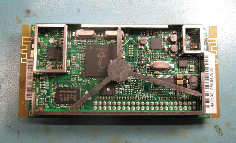
X280072
Feb 02, 2014Cougar Module Type A
Equipment Class
DSS - Part 15 Spread Spectrum Transmitter
X280067
Aug 11, 2013Jongo T6
Equipment Class
DTS - Digital Transmission System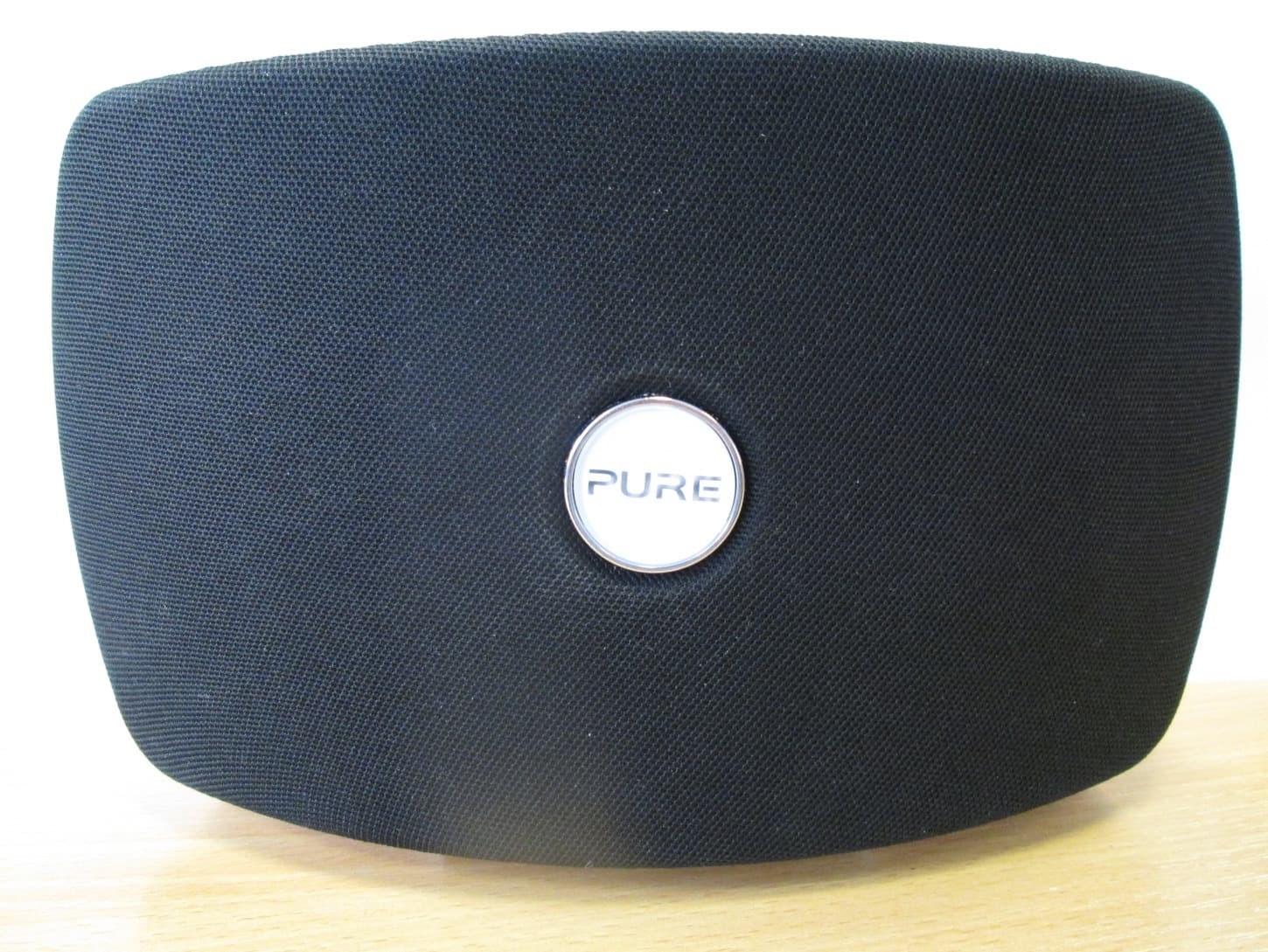
X280070
Aug 03, 2013Jongo T2
Equipment Class
DTS - Digital Transmission System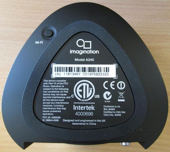
X280068
Aug 01, 2013Jongo A2
Equipment Class
DTS - Digital Transmission System