X2FB-328BTBluetooth Car Kit
GaoYi Tech Limited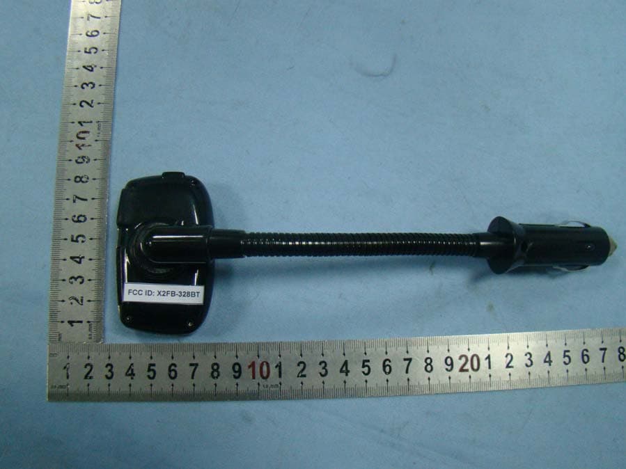
Click to zoom
Application Details
- Equipment Class
- DSS - Part 15 Spread Spectrum Transmitter
- Date of Grant
- Sep 07, 2010
- Application Purpose
- Original Equipment
- Date of Application
- Sep 07, 2010
- Equipment Note
- Bluetooth Car Kit
- Frequency Range
- 2402.00000000 - 2480.00000000
- Company
- GaoYi Tech Limited
- Country
- China
Documents & Files
Document Text
Text extracted from the exhibit documents filed with the FCC. Open a document above to read the original.
Users Manual
Note: Please read this manual carefully before use B-328BT; please check for any special requirement or restriction about the use of Bluetooth wireless technology in your country B-328BT Installation Guide & User Manual Features and Functions: * Bluetooth car kit, compatible with all Bluetooth phones. * CVC technology to eliminate noise and restrain echo, enjoy clear speaking. * Support line-in, USB & SD card. * Caller ID show, support call answering & call rejecting, call transferring and last caller number re-dialing. * Voice dialing supported. (If your phone has the function.) * Bluetooth automatically connection. * Built-in Microphone. * Large 1.44 inch LCD display, support full frequency transmitting (87.5-108.0MHz) * Spring handle support all direction circumgyrated. * EQ mode: Normal; Rock; Pop; Classical; Jazz; Country * Circulation mode: All; Single; Folder; Normal; Random * Steering wheel remote control, operating easily and conveniently. (Optional) Technical Specifications: Excellent sound quality with full duplex communication DSP (Digital Signal Processing) Technology for echo cancellation and background noise reduction Supported BT Profiles: Bluetooth 2.1 +EDR solution (HSP 1.0, HFP 1.5) Bluetooth frequency range: 2.402 ~ 2.480GHz FM transmitting range: 87.5~108.0MHz Operating voltage range: DC 12V~24V (car lighter socket) Charger Output Rating: 5V DC, 1.5A Microphone: Noise Cancelling Support: SD, USB Display: 1.44 inch LCD display Audio In: 2.5mm: Installation 1. Insert the B-328 into the socket of car lighter. 2. Adjust the transmitting frequency of the B-328 to correspond channel between FM87.5~108.0MHz 3. Set the car fm channel the same with B-328 channel, then the B-328 could play music of U-disk or SD/MMC, or other audio source through line-in. Bluetooth function operations Paring with a Bluetooth enabled cell phone 1. With the B-328 ON, long press the Pairing button on the front panel until the Red & Blue LEDs flash which indicating that the unit is ready to be paired. The screen will display “Pairing”. 2. The Bluetooth cell phone will search for the nearby Bluetooth devices, the cell phone will display “ B-328BT” in the list of Bluetooth devices, if you are using a “dongle” type Bluetooth adaptor; follow the manufacturer’s instructions for that device. 3. Select “ B-328BT” to add this Bluetooth device into the list of paired devices. 4. Enter in the PIN Code “0000” and your mobile phone will show that pairing is completed. 5.If pairing is successful, the screen of B-328 will display “Pair OK”, and the Blue LED will flash about every 3 seconds. Operations on the Panel Basic Operations: Answer the call: Short press the key to answer the call when someone calling. Reject the call: Long press the key to reject the call when someone calling. Call transfer: Long press the key to transfer the call between the unit and your mobile phone when in talking. Last number re-dialing: Long press the key to re-dial the last caller number when Bluetooth connected. Voice dialing: Short press the Pairing button to activate the voice dialing. (If your phone support voice dialing.) Turn on/ Turn off Bluetooth: Press and hold the pairing button for 6 seconds to turn on or turn off the Bluetooth. Play/Pause: Short press the key to play the MP3/WMA (optional) file. To pause during playback, press the key. To resume, press it again. Previous/Next: Short press the “ ” “” key to play the previous track or press the key to play the next track. Switch Channel: Press the “ +” or “--” key to switch the open channels. When you switch to a certain channel, the frequency is indicated on the display. Note: There are 206 preset channels: 87.5 MHz. ~108.0MHz Adjust Volume : Press and hold the“ ”decrease volume, or press and hold the “”key to increase volume. Operations on the remote control Remote Control Function: 1, CH key: Set the frequency after selecting the frequency directly by number key. 2, FL+ / FL- key: change the playing folder one by one. 3, CH+/CH- key: Adjusting the frequency with 0.1MHZ by short press, adjusting the frequency quickly by long press. 4, PRVE/NEXT key: Select previous or next song. 5, +/- key: Volume Turn up or Turn down 6. PLAY key: Answer the call: Short press the key to answer the call when someone calling. Reject the call: Long press the key to reject the call when someone calling. Call transfer: Long press the key to transfer the call between the unit to your mobile phone when in talking. Last number re-dialing: Long press the key to re-dial the last caller number when Bluetooth connected. Play/Pause: Short press the key to play the MP3/WMA (optional) file. To pause during playback, press the key. To resume, press it again. 7, Number key: Select song by figure under normal playing state, select frequency after entering into the frequency state. 8, Short press EQ key: Change the playing EQ mode (Rock, Classical, Normal, POP, Jazz, Country) 9, Long press EQ key: Select circulation mode. (ALL, SINGLE, FOLDER, NORMAL, RANDOM) FCC STATEMENT 1. This device complies with Part 15 of the FCC Rules. Operation is subject to the following two conditions: (1) This device may not cause harmful interference, and (2) This device must accept any interference received, including interference that may cause undesired operation. 2. Changes or modifications not expressly approved by the party responsible for compliance could void the user’s authority to operate the equipment. NOTE: This equipment has been tested and found to comply with the limits for a Class B digital device, pursuant to Part 15 of the FCC Rules. These limits are designed to provide reasonable protection against harmful interference in a residential installation. This equipment generates, uses and can radiate radio frequency energy and, if not installed and used in accordance with the instructions, may cause harmful interference to radio communications. However, there is no guarantee that interference will not occur in a…
Text truncated - open the document above for the full version.
Block Diagram
Applicant:Gaoyi Tech Limited FCC ID:X2FB-328BT Block Diagram
ID Label/Location Info
FCC Certification label Sample
ID Label/Location Info
FCC Certification Label Location Sample Label location
Internal Photos
Antenna
Operational Description
Applicant:Gaoyi Tech Limited FCC ID:X2FB-328BT Operation Description Bluetooth car kit is working frequency 2402-2480MHz. 1、 Bluetooth car kit has the 12V power from the cigarette jack. 2、 The 12V power changed into 5V via IC 34063, then 5V power supply for the Bluetooth ,UTC4052 and manostat. 3、 The 5V power changed into 3.3V via XC6206P332, then 3.3V supply for decode IC, transmitter IC and LCD displayer 4、 The 5v power changed into 3.3V via RT9193-33, then 3.3V can supply for Bluetooth MIC working voltage. Antenna is formed by a copper trace on the PCB. The ground wire of PCB is directly connected with ground wire of car charger.
RF Exposure Info
1. RF EXPOSURE 1.1. The Requirement System operating under the provisions of this section shall be operated in a manner that ensures that the public is not exposed to radio frequency energy levels in excess of the Commission’s guidelines. See Section 15.247(b)(4) and Section 1.1307(b)(1) 1.2. Limit For Maximum Permissible Exposure (MPE) Limits for General Population/ Uncontrolled Exposure Frequency Range Electric Field Strength (E) (V/m) Magnetic Field Strength (H) (A/m) (MHz) Power Density (S) () 2 mW/cm Averaging Time 2 E , 2 H or S (minutes) 0.3-1.34 614 1.63 (100)* 30 1.34-30 824/f 2.19/f (180/f)* 30 30-300 27.5 0.073 0.2 30 300-1500 f/1500 30 1500-100,000 1.0 30 F = frequency in MHz, * Plane-wave equivalent power density 1.3. MPE Calculations E(V/m) = 30 P G d ×× , Power Density: S() = 2 mW/cm 2 377 E Where E = Electric Field (V/m) P = Peak Output Power (mW) G = Antenna Numeric Gain (numeric) = 10 x , x = Antenna Gain(dBi) /10 d = Separation Distance (cm) We can change the formula to: S = 2 30 377 PG d ×× × or, d = 30 377 PG S ×× × Because the EUT is belong to general population/uncontrolled exposure. So 1.3.1. We considering the limit of minimum separation distance (d) is 20cm, Maximum Output Power = 0.499mW Antenna Gain = 0(dBi) = 1(numeric) S = 2 30 377 PG d ×× × = 0.99×10 -4 2 mW/cm < 1.0(limit) 2 mW/cm Calculated RF Exposure power density is 0.99 ×10 -4 2 mW/cm, less than the limit. 1.3.2. We considering the limit of power density (S) is 1.0, 2 mW/cm Maximum Output Power = 0.499mW Antenna Gain = 0(dBi) = 1 (numeric) d = 30 377 PG S ×× × = 0.20 cm < 20 cm Calculated RF Exposure separation distance is 0.20 cm, less than the minimum separation distance 1.3.3.FCC Radiation Exposure Statement This equipment complies with FCC radiation exposure limits set forth for an uncontrolled environment. In order to avoid the possibility of exceeding the FCC radio frequency exposure limits, Human proximity to the antenna shall not be less than 20cm(8 inches) during normal operation. Proposed RF exposure safety information to include in User’s Manual.
Schematics
12345678 A B C D 87654321 D C B A Title NumberRevisionSize A3 Date:24-Aug-2010Sheet of File:C:\Documents and Settings\jack\桌面\B-128-AX-BT.DDBDrawn By: 高易B-328 GY_AX3008_KT0803 I2C_CLK I2C_DAT DPDM USB_5V 4 DM 3 DP 2 GND 1 56 USB1 USBSMD A0 1 A1 2 NC 3 GND 4 SDA 5 SCL 6 WP 7 VCC 8 U3 24C02 +3V3 C23 106 SD-CS SDCMD SDDAT SDCLK +3V3 SD Card R13 3K3 R12 3R9 R14 3K3 R17 4K7 SD_6 SD_3 R15 33R +5V KEY C33 104 +3V3 C34 104 GND 1 VOUT 2 VIN 3 U2 XC6206P332MR R18 3R9 C35 106 SD-INSERT R16 33R 主板PCB E2PROM USB C2 27pF C1 27pF DACL DP DM IRDA SDCMDSDDATSDCLK C12 104 I2C_CLK MCLR C13 104 R9 100K C4 104 C6 106 DACR R7 4K7 +3V3 +3V3 +3V3 +3V3+3V3 Main MCU I2C_DAT R8 4K7 C5 106 R10 4K7 SD-INSERT C7 104 R19 4K7 Y1 7.6M I2C_CLK I2C_DAT C18 104 C20 105 C21 105 C22 NC +3V3 C19 104 LCD_CS LCD_RES LCD_A0 C17 NC C16 NC C15 NC C14 NC VDD 1 C86 2 VSS 3 V0 4 V1 5 V2 6 V3 7 V4 8 CAP2N 9 CAP2P 10 CAP1P 11 CAP1N 12 CAP3P 13 VOUT 14 VSS 15 D7 16 D6 17 D5 18 D4 19 D3 20 D2 21 D1 22 D0 23 RD 24 WR 25 A0 26 RES 27 CS 28 LCD1 TXDM12864CF-35 EMI_WR EMI_RD EMID7 EMID6 EMID5 EMID4 EMID0 EMID1 EMID2 EMID3 S1 PREW S2 NEXT S3 P/P S4 B+ S5 A- 123 U4 IR-3V3 IRDA +3V3 IRDA C36105 R20 100R GND 32 RX 31 CTS 30 LED_RED 29 LED_BLUE 28 TX 27 RTS 26 5V 25 GND 24 VBAT 23 1.8V 22 GND 21 GND 1 GND 2 MIC_BIAS 3 MIC_N 4 MIC_P 5 GND 6 GPIO10 7 GPIO9 8 GPIO15 9 1.8V 10 GND 11 GND 12 SPK_N 13 SPK_P 14 GPIO14 15 GPIO13 16 RESET 17 GPIO8 18 WAKEUP 19 GND 20 GND 33 ANT 34 GND 35 GND 36 U6 BCM2044 C24105 C25 105 X1 14 X2 15 X3 11 B 9 Y0 1 Y1 5 Y2 2 Y3 4 A 10 X0 12 X 13 Y 3 VDD 16 VEE 7 VSS 8 INH 6 U10 UTC4052 R_IN L_IN A R_FM L_FM +5V LB1 0R LB2 NC CB2 NC ANT1 VOUT 5 BY 4 VIN 1 GND 2 CE 3 U7 RT9193-33 CB6 475 CB5 103 CB4 475 RB10 100K RB5 2.2K RB6 2.2K RB8 10K CB9 104 MIC MICROPHONE2 RB9 10K CB11 104 CB10 15pF CB7 15pF CB8 106 RB4 47K WAKEUP C3 101 OSCO EMID0EMID1EMID2 EMID3 EMID4 EMID5 EMID6 EMID7 EMI_RD EMI_WR LCD_CS LCD_RES LCD_A0 RXTX CTS BT_TX BT_RX +1V8 +1V8 VCC LCD A SPK_L SPK_R SPK_L1 SPK_R1 R_IN L_IN RED_LED BLUE_LED R L OSI 1 OSO 2 P44 3 P12 4 P17 5 P43 6 P42 7 P41 8 P07 9 P06 10 P05 11 P04 12 P03 13 P02 14 P01 15 P00 16 LDOVDD 17 LDOVSS 18 VPP 19 /LDOEN 20 P36 21 P35 22 P40 23 P34 24 /MCLR 25 EMI_CLE/P33 26 EMI_RD/P32 27 UART_TX/P31 28 UART_RX/P30 29 USBDM 30 USBDP 31 P57 32 P56 33 P55 34 P54 35 P53 36 P52 37 P51 38 P50 39 VDDIO 40 P16 41 DVSS 42 DVDD 43 P15 44 P14 45 P13 46 PLLVDD 47 PLLVSS 48 U1 AX3008_LQFP48 CB16105 RB11 5.1K CB17105 RB12 5.1K RB2 10K RB21 4.7K SPK_L SPK_RSPK_R1 SPK_L1 RX TXBT_RX BT_TX KEY1 KEY2 KEY3 CON KEY1 KEY2 KEY3 +5V LED1 BLUE RB13 100R BLUE_LED LED2 RED RB14 100R RED_LED +5V +5V LINE_IN +5V 1 2 BL101 R11 330R C28 104 C29 106 L1 10uH LINE_IN GND C30 105 C31 105 C37 104 +3V3 +3V3 C38 47pF 1 OSCO +3V3 R_FM L_FM GND 1 XI 2 XO 3 IOVDD 4 GND 5 INL 6 INR 7 SW 8 GND 9 RSTB 10 GND 11 GND 12 SDA 13 SCL 14 GND 15 PA_OUT 16 U5 KT0803 R21 47K L2 100nH C40 101 ANT +3V3 C39 103 B 1 C 3 E 2 Q1 9018 R22 100K +3V3 SD9 1 SD-CS 2 CMD/DI 4 GND 5 VCC 6 CLK 7 GND 8 D0/DO 9 SD8 10 INSERT 3 WP 11 12 13 J4 SD-CARD R5 2K R6 2K C10 392 C11 392 DACL DACR R1 6K8 R2 6K8 C9 105 C8 105 L R RB16 10K RX Q3 3904 Q4 3904 Q2 8550 +3V3 RB17 4.7K RB18 4.7K +1V8 RB20 1K RB19 51R RB22 10K RB23 10K PIO9PIO10 PIO10 PIO9 VOL- VOL+ Q5 3904 RB24 10K WAKEUP CON VOL+ VOL- KEY1 CB18 106 +5V +1V8 CB21 103 D5 1N4148 D4 1N4148 VCC A 1 B 2 C 3 D 4 E 5 F 6 J1 LINE-IN S6 EQ R23 0R R25 0R R24 0R R26 0R KEY3 GND WAKEUP UnRegistered 1234 A B C D 4321 D C B A Title NumberRevisionSize A4 Date:25-Aug-2010Sheet of File:E:\公司资料\旧资料\公司资料\OTI方案资料\共用电源板PCB.DdbDrawn By: D1 1N5819 3A/20v CE1 220UF/25V CE2 470UF/25VC2 104 C3 104C4 470p L1 33uH L2 100uH R2 3.6K R3 1K +12 +5.5 DR 8 IS 7 VIN 6 CII 5 SC 1 SE 2 TC 3 GND 4 U1 34063 R1 0.33R/0.5W ANT L3 0R GNDAGND C2 104 UnRegistered
Test Report
Page 1 of 66 FCC ID: X2FB-328BT ACCURATE TECHNOLOGY CO. LTD Report No.: ATE20101908 APPLICATION CERTIFICATION On Behalf of Gaoyi Tech Limited Bluetooth Car Kit Model No.: B-328BT FCC ID: X2FB-328BT Prepared for : Gaoyi Tech Limited Address : 5th Floor, Building F2, Hua Feng Industrial Zone Hangcheng Road, Xi Xiang Town, Bao An District Shenzhen, China Prepared by : ACCURATE TECHNOLOGY CO. LTD Address : F1, Bldg. A, Changyuan New Material Port, Keyuan Rd. Science & Industry Park, Nanshan, Shenzhen, Guangdong P.R. China Tel: (0755) 26503290 Fax: (0755) 26503396 Report Number : ATE20101908 Date of Test : September 4-7, 2010 Date of Report : September 8, 2010 Page 2 of 66 FCC ID: X2FB-328BT ACCURATE TECHNOLOGY CO. LTD Report No.: ATE20101908 TABLE OF CONTENTS Description Page Test Report Certification 1. GENERAL INFORMATION .......................................................................................................... 5 1.1. Description of Device (EUT)....................................................................................................................5 1.2. Description of Test Facility ......................................................................................................................6 1.3. Measurement Uncertainty.........................................................................................................................6 2. MEASURING DEVICE AND TEST EQUIPMENT ..................................................................... 7 3. OPERATION OF EUT DURING TESTING ................................................................................. 8 3.1. Operating Mode ........................................................................................................................................8 3.2. Configuration and peripherals ..................................................................................................................8 4. TEST PROCEDURES AND RESULTS ......................................................................................... 9 5. 20DB BANDWIDTH TEST............................................................................................................ 10 5.1. Block Diagram of Test Setup..................................................................................................................10 5.2. The Requirement For Section 15.247(a)(1) ............................................................................................10 5.3. EUT Configuration on Measurement .....................................................................................................10 5.4. Operating Condition of EUT ..................................................................................................................10 5.5. Test Procedure ........................................................................................................................................11 5.6. Test Result ..............................................................................................................................................11 6. CARRIER FREQUENCY SEPARATION TEST........................................................................ 15 6.1. Block Diagram of Test Setup..................................................................................................................15 6.2. The Requirement For Section 15.247(a)(1) ............................................................................................15 6.3. EUT Configuration on Measurement .....................................................................................................15 6.4. Operating Condition of EUT ..................................................................................................................15 6.5. Test Procedure ........................................................................................................................................16 6.6. Test Result ..............................................................................................................................................16 7. NUMBER OF HOPPING FREQUENCY TEST ......................................................................... 20 7.1. Block Diagram of Test Setup..................................................................................................................20 7.2. The Requirement For Section 15.247(a)(1)(iii) ......................................................................................20 7.3. EUT Configuration on Measurement .....................................................................................................20 7.4. Operating Condition of EUT ..................................................................................................................20 7.5. Test Procedure ........................................................................................................................................21 7.6. Test Result ..............................................................................................................................................21 8. DWELL TIME TEST ..................................................................................................................... 25 8.1. Block Diagram of Test Setup..................................................................................................................25 8.2. The Requirement For Section 15.247(a)(1)(iii) ......................................................................................25 8.3. EUT Configuration on Measurement .....................................................................................................25 8.4. Operating Condition of EUT ..................................................................................................................25 8.5. Test Procedure ........................................................................................................................................26…
Text truncated - open the document above for the full version.
Test Setup Photos
Radiated emissions test < 1GHz Radiated emissions test > 1GHz
Contact Information
Applicant
Micheal Lee(Manager)
Test Firm
Accurate Technology Co., Ltd.Sean Liu
Technical Specifications
| # | Rule Parts | Frequency Range | Power Output |
|---|---|---|---|
| 1 | 15C | 2.40 GHz - 2.48 GHz | 500.00 µW |
Other Applications from GaoYi Tech Limited
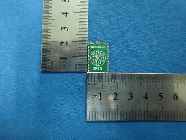
X2FB-368BT
Jun 26, 2011BLUETOOTH CAR KIT
Equipment Class
DXX - Part 15 Low Power Communication Device Transmitter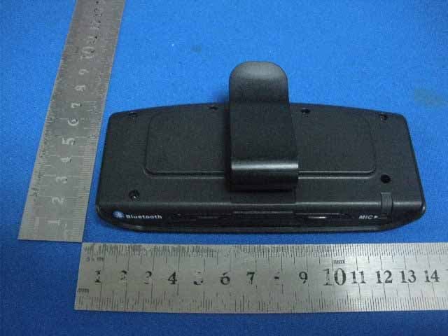
X2FB-800
Dec 16, 2009BLUETOOTH CAR KIT
Equipment Class
DXX - Part 15 Low Power Communication Device Transmitter