X2NBL-LW08-5WLAN 11b/g/n MINI PCIE MODULE
B-LINK ELECTRONIC LIMITED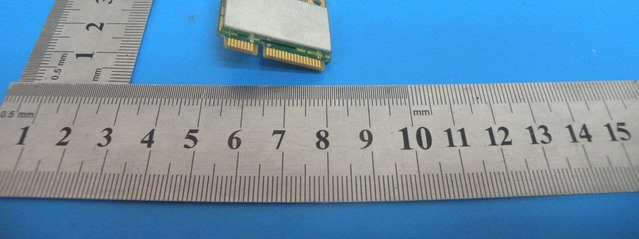
Click to zoom
Application Details
- Equipment Class
- DTS - Digital Transmission System
- Date of Grant
- Oct 24, 2013
- Application Purpose
- Original Equipment
- Date of Application
- Oct 24, 2013
- Equipment Note
- WLAN 11b/g/n MINI PCIE MODULE
- Frequency Range
- 2422.00000000 - 2452.00000000
- Company
- B-LINK ELECTRONIC LIMITED
- Country
- China
Documents & Files
Document Text
Text extracted from the exhibit documents filed with the FCC. Open a document above to read the original.
Users Manual
50 430*187*90mm RTL8192CE Chipset BL-LW08-5 29.8mm 26.5mm Package Size: Product Features Product description Product Specifications Bulk Net weight (kg)Gross weight (kg)Cubic meter(mm) Pcs/box Carton MINI PCI-E 300M WIRELESS MODULE This product is a high-speed PCI-E wireless modules, interconnected with other wireless devices to meet the standards, support for t h e l a t e s t 6 4 / 1 2 8 b i t W E P d a t a e n c r y p t i o n , s u p p o r t W P A - P S K / W P A 2 - P S K , W P A / W P A 2 s ec ur it y m ec hanis m . This pr oduc t uses the 11N w i r e l e s s technology, compatible IEEE802.11b/g/n standard wireless transmission speeds up to 300Mbps. Compared the traditional 54Mbps11g products and 150Mbps products, with higher wireless b a n d w i d t h wit hin the LAN data transmission more efficient, and effective in reducing the network delay, so that voice and video, online games, online on demand is more fluid. ◎ Support standards: the IEEE 802.11b, the IEEE 802.11g, the IEEE 802.11n ◎ Automatically detect the network and the transmission rate ◎ Support 64/128 bit WEP data encryption, support WPA-PSK/ WPA2-PSK, WPA/WPA2 security to protect wireless network Infringement and misappropriation ◎ Support WMM, voice and video services to more fluid The ◎ Installation and configuration simple, plug and play , f as t and convenient ◎ Support Windows XP/Vista/WIN7/LINUX operating system PSP 网络摄像头 GPS 数码相框 Table PC Digital photo frame Netbooks Item IEEE 802.11b,IEEE 802.11g, IEEE 802.11n 2.4-2.4835GHz Transmission rate 15dBm(MAX) Interface Type 11 Working channel Description 29.8*26.5mm*1 Master Model RTL8192CE 300 Mbps(MAX) PCI Express 270M: -73dBm@10% PER 130M: -73dBm@10% PER 108M: -73dBm@10% PER 54M: -73dBm@10% PER 11M: -85dBm@8% PER 6M: -88dBm@10% PER 1M: -90dBm@8% PER Windows XP/Vista/WIN7LINUX/ Standards Frequency Range Work Mode Ad-Hoc Infrastructure Support Operating System Wireless Range Indoors up to 100m, Outdoors up to300m. Wireless Transmit Power Receiver Sensitivity Operating Temperature 0 C~40 C Operating Humidity 10% ~ 90%, non condensation Storage Humidity 5%~90%, non condensation Dimensions ° ° Storage Temperature -40 C~70 C ° ° Add:NO 268,FuQian Rd,Jutang Community,GuanLan Town BaoAn District,ShenZhen,518110,China Tel:+86-755-28023440 Fax:+86-755-28029002 Email:[email protected] http//www.lefen.com 2mm 1mm Web camera This WLAN 11b/g/n 2x2 MINI PCIE MODULE has two exactly the same antenna which is the Integral Dipole Antenna with 1 dBi gain. FCC ID: X2NBL-LW08-5 This device complies with Part 15 of the FCC Rules. Operation is subject to the following two conditions: (1) this device may not cause harmful interference, and (2) this device must accept any interference received, including interference that may cause undesired operation. FCC Caution: Any changes or modifications not expressly approved by the party responsible for compliance could void the user's authority to operate the equipment. NOTE: This equipment has been tested and found to comply with the limits for a Class B digital device, pursuant to Part 15 of the FCC Rules. These limits are designed to provide reasonable protection against harmful interference in a residential installation. This equipment generates, uses and can radiate radio frequency energy and, if not installed and used in accordance with the instructions, may cause harmful interference to radio communications. However, there is no guarantee that interference will not occur in a particular installation. If this equipment does cause harmful interference to radio or television reception, which can be determined by turning the equipment off and on, the user is encouraged to try to correct the interference by one or more of the following measures: -- Reorient or relocate the receiving antenna. -- Increase the separation between the equipment and receiver. -- Connect the equipment into an outlet on a circuit different from that to which the receiver is connected. -- Consult the dealer or an experienced radio/TV technician for help. The device complies with industry Canada license-exempt RSS standard(s). Operation of this device is subject to the following two conditions: (1) this device may not cause interference, and (2) this device must accept any interference, including interference that may cause undesired operation of the device. Le présent appareil est conforme aux CNR d'Industrie Canada applicables aux appareils radio exempts de licence. L'exploitation est autorisée aux deux conditions suivantes : (1) l'appareil ne doit pas produire de brouillage, et (2) l'utilisateur de l'appareil doit accepter tout brouillage radioélectrique subi, même si le brouillage est susceptible d'en compromettre le fonctionnement." For product available in the UAS/Canada market, ony channel 1-11 can be operated, selection of other channels is not possible. IMPORTANT NOTE: Integration is strictly limited to mobile/fixed categorized end-products where a separation distance of at least 20 cm between the radiating part and any human body can be assured during normal operating conditions. IMPORTANT NOTE: In the event that these conditions can not be met (for example certain laptop configurations or co-location with another transmitter).then the FCC authorization is no longer considered valid and the FCC ID can not be used on the final product. In these circumstances, the OEM integrator will be responsible for re-evaluating the end product (including the transmitter) and obtaining a separate FCC authorization. IMPORTANT NOTE: This module is intended for OEM integrator only and the OEM integrators are instructed to ensure that the end user has no manual instructions to remove or install the device. The OEM integrator is still responsible for the FCC compliance requirement of the end product, which integrates this module. LABEL OF THE END PRODUCT: The final end product must be labeled in a visible area with the following “Contains TX FCC ID: X2NBL-LW08-5” .If the size of the e…
Text truncated - open the document above for the full version.
Cover Letter(s)
B-LINK ELECTRONIC LIMITED Federal Communications Commission Equipment Authorization Branch 7435 Oakland Mills Road Columbia, MD 21046 Request for Confidentiality Company name: B-LINK ELECTRONIC LIMITED FCC ID : X2NBL-LW08-5 FCC Part 15 Certification Gentlemen, Pursuant to 47 CFR 0.457(d)(1)(ii) and 0.459 we hereby requests permanent confidentiality of the following documents for the subject application: Exhibit Type Description ☒ Schematics All circuitry of devices and component values ☒ Block Diagrams Details of device showing the frequency of all oscillators ☒ Operational Description Description of the circuit functions Note: Exhibit types that are commonly held confidential are: (1) Schematics, (2) Block Diagrams, (3) Bill Of Materials, (4) Operational Descriptions. Any exhibit NOT granted confidentiality is viewable on the FCC website as soon as a grant is issued. These documents contain detailed system and equipment description and related information about the product which we considers to be proprietary, confidential and a custom design and otherwise would not release to the general public. Since the design is a basis from which future technological products will evolve, we consider that this information would be of benefit to its competitors and that the disclosure of the information in these documents would give competitors an unfair advantage in the market. Yours sincerely, Signatory Name Jianjun Xia Position Engineer Company Name B-LINK ELECTRONIC LIMITED Address RenMing Road, FuMin Village, GuanLan, Baoan District, Shenzhen, China Tel +86-755-28023440 Fax +86-755-28029002 Email [email protected]
Cover Letter(s)
B-LINK ELECTRONIC LIMITED Date: 17.10.2013 Authority to Act as an Agent We declare that the following representative (agent) Name Mark Zhu Position Manager Company Name Shenzhen Certification Technology Service Co., Ltd. Address 2F, Building B, East Area of Nanchang Second Industrial Zone, Gushu 2 nd Road, Bao’an District, Shenzhen 518126, P.R. China Tel / Fax 0755-86375541/0755-26736857 Email [email protected] to act on our behalf on all matters concerning the application and documents submitted to PHOENIX TEST-LAB for product certification below Product Name WLAN 11b/g/n MINI PCIE MODULE Model Name BL-LW08-5 Brand Name N/A . Yours sincerely, Signatory Name Jianjun Xia Position Engineer Company Name B-LINK ELECTRONIC LIMITED Address RenMing Road, FuMin Village, GuanLan, Baoan District, Shenzhen, China Tel +86-755-28023440 Fax +86-755-28029002 Email [email protected] In case of FCC, we certify that we are not subject to a denial of Federal benefits, that include FCC benefits, pursuant to Section 5301 of the Anti-Drug Abuse Act of 1988, 21 U.S.C. §862 because of a conviction for possession or distribution of a controlled substance.
Cover Letter(s)
Ersteller: D. Brandhorst Revision: 00 Erstelldatum: 21.06.07 Datum: 00.00.00 Seite 1 von 1 B-LINK ELECTRONIC LIMITED Date: 10/17/2013 Subject: Ad Hoc Mode Function Declaration FCC ID: X2NBL-LW08-5 To Whom it may concern, This device is acting as slave and operating in 2412-2462MHz band. Ad Hoc function is supported but not able to operate on non-US frequencies. Please contact the one signed below or the authorized agent for this filing. Thank you. Regards, Signatory (YOUR CONTACT DETAILS) Name : Jianjun Xia Position : Engineer Company: B-LINK ELECTRONIC LIMITED Adress : RenMing Road, FuMin Village, GuanLan, Baoan District, Shenzhen, China Tel. : +86-755-28023440 Fax : +86-755-28029002 Email : [email protected]
Cover Letter(s)
FCC Modular Approval Request To the FCC or FCC TCB handling this application Hereby we, Company (grantee) B-LINK ELECTRONIC LIMITED Addresss RenMing Road, FuMin Village, GuanLan, Baoan District, Shenzhen, China City / ZIP / State / Country Shenzhen/China request modular approval for the certification of our equipment within this application, identified by: FCC ID: X2NBL-LW08-5 The table below contains justification for modular approval of this equipment. Requirement per DA 00-1407 Explanation from grantee 1. The modular transmitter must have its own RF shielding. Has RF shielding. 2.The modular transmitter must have buffered modulation/data inputs (if such inputs are provided) to ensure that the module will comply with Part 15 requirements under conditions of excessive data rates or over-modulation. The modular have buffered modulation/data inputs.(RTL8192CE) 3. The modular transmitter must have its own power supply regulation. The modular transmitter have its own power supply regulation.(Chip MCARD regulation DC 3.3V) 4.The modular transmitter must comply with the antenna requirements of Section 15.203 and 15.204(c). The antenna must either be permanently attached or employ a “unique” antenna coupler (at all connections between the module and the antenna, including the cable).. This module is equipped with two integral dipole antennas, please refer to the External Photo for the detail 5. The modular transmitter must be tested in a stand-alone configuration, i.e., the module must not be inside another device during testing. This is intended to demonstrate that the module is capable of complying with Part 15 emission limits regardless of the device into which it is eventually installed. The module was tested in a stand-alone configuration, please refer to the Setup Photo for the detail 6. The modular transmitter must be labeled with its own FCC ID number, and, if the FCC ID is not visible when the module is installed inside another device, then the outside of the device into which the module is installed must also display a label referring to the enclosed module. This exterior label can use wording such as the following: “Contains Transmitter Module FCC ID: X2NBL-LW08-5” or “Contains FCC ID: X2NBL-LW08-5.” Any similar wording that expresses the same meaning may be used. The Grantee may either provide such a label, an example of which must be included in the application for equipment authorization, or, must provide adequate instructions along with the module which explain this requirement. In the latter case, a copy of these instructions must be included in the application for equipment authorization. Please refer to label sample exhibit - host labeling is described in integration manual 7. The modular transmitter must comply with any specific rule or operating requirements applicable to the transmitter and the manufacturer must provide adequate instructions along with the module to explain any such requirements. A copy of these instructions must be included in the application for equipment authorization. For example, there are very strict operational and timing requirements that must be met before a transmitter is authorized for operation under Section 15.231. For instance, data transmission is prohibited, except for operation under Section 15.231(e), in which case there are separate field strength level and timing requirements. Compliance with these requirements must be assured. The required FCC rule has been fulfilled and all the instructions for the maintaining compliance have been clearly stated in the User Manual. 8. The modular transmitter must comply with any applicable RF exposure requirements. For example, FCC Rules in Sections 2.1091, 2.1093 and specific Sections of Part 15, including 15.319(i), 15.407(f), 15.253(f) and 15.255(g), require that Unlicensed PCS, UNII and millimetre wave devices perform routine environmental evaluation for RF Exposure to demonstrate compliance. In addition, spread spectrum transmitters operating under Section 15.247 are required to address RF Exposure compliance in accordance with Section 15.247(b)(4). Modular transmitters approved under other Sections of Part 15, when necessary, may also need to address certain RF Exposure concerns, typically by providing specific installation and operating instructions for users, installers and other intere sted parties to ensure compliance. The MPE evaluation with 20cm distance restriction is submitted for the compliance of RF Exposure requirement. Attestation (by grantee) City and Country: Date: Name: (this must be a person) Function: Signature: (or official company stamp) Shenzhen/China 2013.09.15 Jianjun Xia Engineer
External Photos
Top View Bottom View Front View Right View Rear View Left View
ID Label/Location Info
30mm 12mm FCC ID: X2NBL-LW08-5 B-LINK ELECTRONIC LIMITED Model: BL-LW08-5 Product: WLAN 11b/g/n MINI PCIE MODULE
ID Label/Location Info
Label Location
Internal Photos
Port 2 WIFIAntenna Port 1 WIFI Antenna
RF Exposure Info
MPE ESTIMATION FCC ID: X2NBL-LW08-5 1,Limit for General Population/ Uncontrolled Exposures Frequency Power density (mW/ cm 2 ) Averaging time(minutes) 300MHz----1.5GHz F/1500 30 1.5GHz---100GHz 1.0 30 Note: F= Frequency in MHz 2, Estimation Result Mode CH PK Output power(dBm) Output power(mW) Antenna Gain(dBi) Antenna Gain (linear) MPE (mW/cm²) CH1 12.31 17.02159 1 1.2589 0.004263 CH6 11.99 15.81248 1 1.2589 0.00396 11b CH11 13.70 23.44229 1 1.2589 0.005871 CH1 10.59 11.45513 1 1.2589 0.002869 CH6 11.69 14.75707 1 1.2589 0.003696 11g CH11 12.45 17.57924 1 1.2589 0.004403 CH1 10.31 10.73989 1 1.2589 0.00269 CH6 11.52 14.19058 1 1.2589 0.003554 11n/HT20 CH11 10.51 11.24605 1 1.2589 0.002817 CH1 10.73 11.83042 1 1.2589 0.002963 CH4 11.38 13.74042 1 1.2589 0.003441 11n/HT40 CH7 11.94 15.63148 1 1.2589 0.003915 Note: Note: The estimation distance is 20cm Note: PK Output power max is for antenna 1. PK Output power= conducted power. Conducted power see the test report STI130802125, antenna gain=1dBi. Mode CH PK Output power(dBm) Output power(mW) Antenna Gain(dBi) Antenna Gain (linear) MPE (mW/cm²) CH1 11.60 14.4544 1 1.2589 0.00362 CH6 11.57 14.35489 1 1.2589 0.003595 11b CH11 11.34 13.61445 1 1.2589 0.00341 CH1 10.62 11.53453 1 1.2589 0.002889 CH6 10.94 12.41652 1 1.2589 0.00311 11g CH11 10.48 11.16863 1 1.2589 0.002797 CH1 10.16 10.37528 1 1.2589 0.002599 CH6 11.14 13.0017 1 1.2589 0.00326 11n/HT20 CH11 10.28 10.66596 1 1.2589 0.002671 CH1 9.94 9.862795 1 1.2589 0.0024702 CH4 10.18 10.42317 1 1.2589 0.002611 11n/HT40 CH7 10.10 10.23293 1 1.2589 0.002563 Note: Note: The estimation distance is 20cm Note: PK Output power max is for antenna 2. PK Output power= conducted power. Conducted power see the test report STI130802125, antenna gain=1dBi. Mode CH PK Output power(dBm) Output power(mW) Directional Gain(dBi) Antenna Gain (linear) MPE (mW/cm²) CH1 13.25 21.13489 4.01 2.5177 0.010586 CH6 14.34 27.16439 4.01 2.5177 0.013607 11n/HT20 CH11 13.41 21.92805 4.01 2.5177 0.010984 CH1 13.36 21.67704 4.01 2.5177 0.010858 CH4 13.83 24.15461 4.01 2.5177 0.012099 11n/HT40 CH7 14.13 25.88213 4.01 2.5177 0.012964 Note: Note: The estimation distance is 20cm Note: PK Output power max is for antenna 1 and antenna 2 simultaneously transmit. PK Output power= conducted power. Conducted power see the test report STI130802125, antenna gain=1dBi. Directional gain = antenna gain + array gain =1+10log(2)=4.01
Test Report
Shenzhen Certification Technology Service Co., Ltd 2F, Building B, East Area of Nanchang Second Industrial Zone, Gushu 2nd Road, Bao'an District, Shenzhen 518126, P.R. China. FCC ID: X2NBL-LW08-5 Page 1 of 126 TEST REPORT FCC ID: X2NBL-LW08-5 Applicant : B-LINK ELECTRONIC LIMITED Address : RenMing Road, FuMin Village, GuanLan, Baoan District, Shenzhen, China Equipment under Test (EUT): Name : WLAN 11b/g/n MINI PCIE MODULE Model : BL-LW08-5 Standards : FCC PART 15, SUBPART C : 2012 (Section 15.247) / IC RSS-210 ISSUE 8 with amendment June 2010 Report No. : STI130802125 Date of Test : August 30-September 5, 2013 Date of Issue : September 6, 2013 Test Result : PASS * * In the configuration tested, the EUT complied with the standards specified above Authorized Signature (Mark Zhu) General Manager The manufacture should ensure that all the products in series production are in conformity with the product sample detailed in this report. If the product in this report is used in any configuration other than that detailed in the report, the manufacturer must ensure the new system complies with all relevant standards. Any mention of Shenzhen Certification Technology Service Co., Ltd. Or test done by Shenzhen Certification Technology Service Co., Ltd. Approvals in connection with, distribution or use of the product described in this report must be approved by Shenzhen Certification Technology Service Co., Ltd. Approvals in writing. Report No.: STI130802125 FCC ID: X2NBL-LW08-5 Page 2 of 126 TABLE OF CONTENT Description Page 1 General Information--------------------------------------------------------------------------------------4 1.1 Description of Device (EUT)---------------------------------------------------------------------4 1.2 Description of Test Facility-----------------------------------------------------------------------5 2 EMC Equipment List--------------------------------------------------------------------------------------6 3 Test Procedure---------------------------------------------------------------------------------------------7 4 Summary of Measurement---------------------------------------------------------------------------8 4.1 Summary of test result-----------------------------------------------------------------------------8 4.2 Test connection-------------------------------------------------------------------------------------8 4.3 Assistant equipment used for test----------------------------------------------------------------9 4.4 Test mode--------------------------------------------------------------------------------------------9 4.5 Channel list-----------------------------------------------------------------------------------------10 4.6 Test Conditions------------------------------------------------------------------------------------10 4.7 Measurement Uncertainty (95% confidence levels, k=2)------------------------------------10 5 Spurious Emission------------------------------------------------------------------------------------11 5.1 Radiation Emission--------------------------------------------------------------------------------11 5.1.1 Radiation Emission Limits(15.209)-------------------------------------------------------------11 5.1.2 Test Setup-------------------------------------------------------------------------------------------11 5.1.3 Test Procedure-------------------------------------------------------------------------------------13 5.1.4 Test Equipment Setting For emission test Result---------------------------------------------13 5.1.5 Test Condition-------------------------------------------------------------------------------------13 5.1.6 Test Result------------------------------------------------------------------------------------------13 6 POWER LINE CONDUCTED EMISSION-------------------------------------------------------46 6.1 Conducted Emission Limits(15.207)-----------------------------------------------------------46 6.2 Test Setup-------------------------------------------------------------------------------------------46 6.3 Test Procedure-------------------------------------------------------------------------------------47 6.4 Test Results-----------------------------------------------------------------------------------------47 7 Conducted Maximum Output Power-----------------------------------------------------------50 7.1 Test limit--------------------------------------------------------------------------------------------50 7.2 Test Procedure-------------------------------------------------------------------------------------50 7.3 Test Setup-------------------------------------------------------------------------------------------50 7.4 Test Results-----------------------------------------------------------------------------------------50 8 PEAK POWER SPECTRAL DENSITY-----------------------------------------------------------54 8.1 Test limit--------------------------------------------------------------------------------------------54 8.1.1 Please refer section15.247.----------------------------------------------------------------------54 8.2 Method of measurement--------------------------------------------------------------------------54 8.3 Test Setup-------------------------------------------------------------------------------------------54 8.4 Test Results-----------------------------------------------------------------------------------------55 9 Bandwidth-----------------------------------------------------------------------------------------------70 9.1 Test limit--------------------------------------------------------------------------------------------70 9.2 Method of measurement--------------------------------------------------------------------------70 9.3 Test Setup-------------------------------------------------------------------------------------------70 9.4 Test Results-----------------------------------------------------------------------------------------70 10 Band Edge Check--------------------------------…
Text truncated - open the document above for the full version.
Test Setup Photos
Photographs-Radiated Emission Test Setup in Chamber Below 1G Above 1G Photographs-Test Connection Photographs-Conducted Emission Test Setup
Contact Information
Applicant
Jianjun Xia(Engineer)
Test Firm
Shenzhen Certification Technology Service Co., LtdMark Zhu
Technical Specifications
| # | Rule Parts | Frequency Range | Power Output |
|---|---|---|---|
| 2 | 15C | 2.42 GHz - 2.45 GHz | 26.00 mW |
Other Applications from B-LINK ELECTRONIC LIMITED
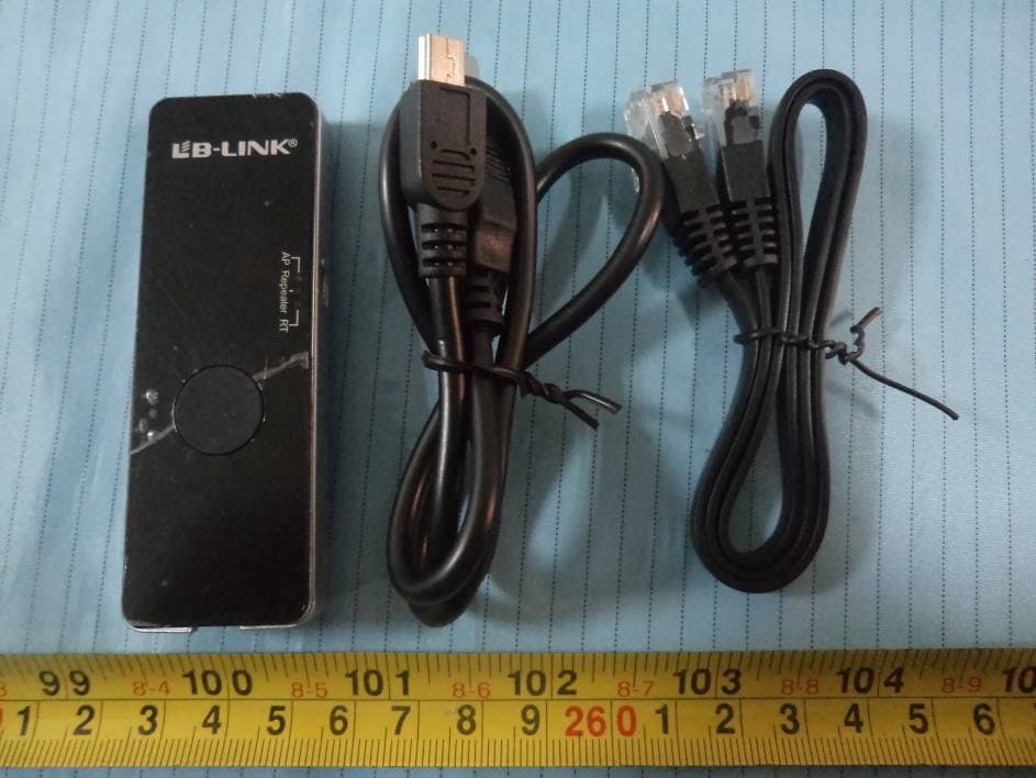
X2NBL-MP02
Jan 16, 2014150M Wireless N Wi-Fi Repeater
Equipment Class
DTS - Digital Transmission System
X2NBL-MP01
Mar 20, 201211N 150M WIRELESS Router
Equipment Class
DTS - Digital Transmission System
X2NBL-LW02-2
Jan 12, 2012wifi module
Equipment Class
DTS - Digital Transmission System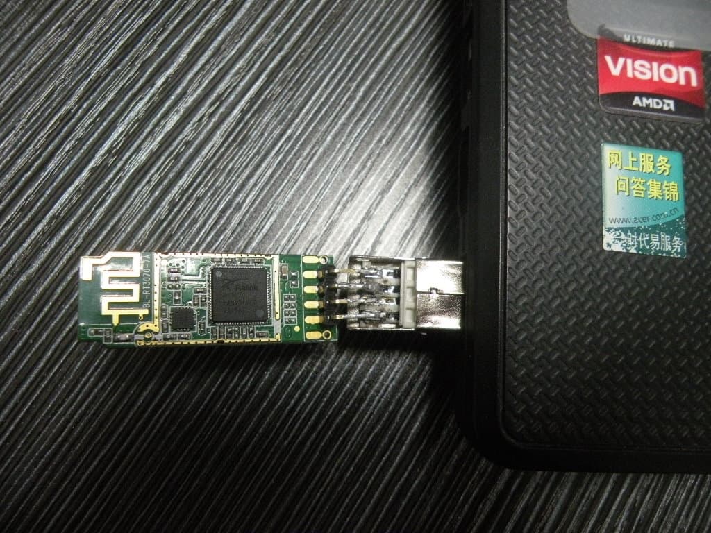
X2NBL-LW0XX
Dec 22, 2011Mobile Verifier 3
Equipment Class
DTS - Digital Transmission System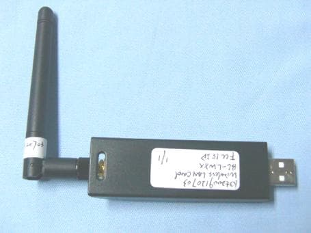
X2NBL-LWXX
Dec 23, 2009WIRELESS LAN CARD
Equipment Class
DTS - Digital Transmission System