X2NBL-LW0XXMobile Verifier 3
B-LINK ELECTRONIC LIMITED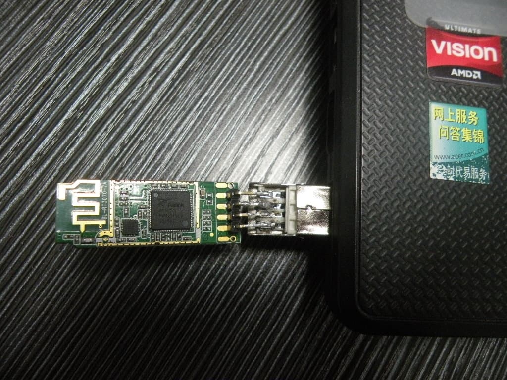
Click to zoom
Application Details
- Equipment Class
- DTS - Digital Transmission System
- Date of Grant
- Dec 22, 2011
- Application Purpose
- Original Equipment
- Date of Application
- Dec 22, 2011
- Equipment Note
- Mobile Verifier 3
- Frequency Range
- 2412.00000000 - 2462.00000000
- Company
- B-LINK ELECTRONIC LIMITED
- Country
- China
Documents & Files
Document Text
Text extracted from the exhibit documents filed with the FCC. Open a document above to read the original.
Users Manual
深 圳 必 联 电 子 有 限 公 司 SHENZHEN B-LINK ELECTRONICS CO.,LTD. IEEE 802.11 b/g/n WiFi Module Model: BL-LWXX Series Revision:7A Date:2011.08.06 TEL:+86-0755-28023453 FAX:+86-0755-28029002 EMAIL:[email protected] http://www.b-link.net.cn ADD: NO 37,FuQian Rd, JuTang Community,GuanLan town BaoAn district,ShenZhen, 518110,China 1: Introduction: BL-LWXX Serives product is a low power, high linear output power, in line with IEEE802.11B / G /N standard, IEEE 802.11i security protocol support, and the standard IEEE 802.11e quality of service 150M USB wireless card, with other meet the standard of wireless devices interconnected, supporting the latest WEP 64/128 bit data encryption, support WPA-PSK/WPA2-PSK, WPA/WPA2 security, wireless transmission rates of up to 150M, 11G is the product of 3 times normal, the All the smart set high gain antenna, can adapt to different working environment, desktop or notebook computer users, and other wireless networking devices need to achieve easy access to the wireless network. 2: Application: Wireless Internet, network cameras, set-top box GPS, hard disk player, wireless networking equipment and other needs 3: product Features Project Description Supported protocols and standards IEEE 802.11N IEEE 802.11G, IEEE 802.11B CSMA/CA ACK Bus Interface USB1.1 USB2.0 Frequency range 2.4-2.4835GHZ Data modulation 14 Data modulation OFDM/DBPSK/DQPSK/CCK Mode Infrastructure or Ad-Hoc Transmission rate 150/54/48/36/24/18/12/9/6/5.5/2/1M Sensitivity @PER 54/150M:-72dBm@10%PER,11M:-85dBm@8%PER 6M: -88dBm@10%PER , 1M: -90dBm@8%PER Transmit power 54M/150M:15DBM, 11M:19DBM Antenna gain 2dbi LED Instructions Status Indicator Transmission distance Indoor up to 100m, outdoor up to 300 meters (depends on the environments Operating System Support WIN2000/XP/VISTA/LINUX/WINCE/WIN7 Operating voltage DC 5V +-0.2V Environment: Operating temperature:0ºC---40ºC Work Humidity:10%---90% Size (L*W*H) 39.4MM*15MM*3MM Software Version VER:2.0 IC RALINK 3070 4: Description of the test parameters Test Project Transmit power EVM Freq Err Receiver Sensitivity Test Data 15.57dbm -30.6dbm 0.03khz -72dbm 5: System Support Platform Operating System CPU Supplier Drive WIN2000/XP/VISTA/WIN7 X86 Platform Support LINUX2.4/2.6 ARM, MIPSII Support WINCE5.0/6.0 ARM ,MIPSII Support 6: Product pin definition TOP Built-in antenna test points DC 5V UDM- UDP+ GND Bottom 7:Product Size All dimensional tolerances +-0.2MM RF warning statement: The device has been evaluated to meet general RF exposure requirement. The device can be used in portable exposure condition without restriction. Changes or modifications not expressly approved by the party responsible for compliance could void the user's authority to operate the equipment. NOTE: This equipment has been tested and found to comply with the limits for a Class B digital device, pursuant to Part 15 of the FCC Rules. These limits are designed to provide reasonable protection against harmful interference in a residential installation. This equipment generates, uses and can radiate radio frequency energy and, if not installed and used in accordance with the instructions, may cause harmful interference to radio communications. However, there is no guarantee that interference will not occur in a particular installation. If this equipment does cause harmful interference to radio or television reception, which can be determined by turning the equipment off and on, the user is encouraged to try to correct the interference by one or more of the following measures: -- Reorient or relocate the receiving antenna. -- Increase the separation between the equipment and receiver. -- Connect the equipment into an outlet on a circuit different from that to which the receiver is connected. -- Consult the dealer or an experienced radio/TV technician for help. FCC ID: X2NBL-LW0XX This device complies with Part 15 of the FCC Rules. Operation is subject to the following two conditions: (1) this device may not cause harmful interference, and (2) this device must accept any interference received, including interference that may cause undesired operation.
Cover Letter(s)
SCS-F18: Project and Product Certification Representative Authorization Letter Page 1 of 2 Rev 2.0 2206 Ringwood Avenue San Jose, CA 95131 Tel: 408-526-1188 Fax: 408-526-1088 Email: [email protected] Project and Product Certification Representative Authorization Letter Reason for Amendment (current / obsolete) Revision History Approved Date From To Initial Release (current) 1.0 1.0 Nov-14-2006 Revised wording (current) 1.0 2.0 Sept–25-2007 SCS-F18: Project and Product Certification Representative Authorization Letter Page 2 of 2 Rev 2.0 B-LINK ELECTRONI C LIMITED (December 11, 2011) To: SIEMIC, INC. 2206 Ringwood Avenue, San Jose, CA 95131 USA Dear Sir/Madam, Re: Project and Product Certification Representative Authorization Letter We, B-LINK ELECTRONI C LIMITED hereby authorize SIEMIC, INC. to act as a Certification Body for certifying for the following project(s): FCC ID: X2NBL-LW0XX Product name: wifi module Model: BL-XXXX Series We affirm that between SIEMIC and B-LINK ELECTRONI C LIMITED, any difference in understanding, including test plan, measurement methods, applicable standards and relevant procedures and processes have been resolved prior to commencement of testing activities. Sincerely, Jianjun Xia / Engineer Title: Engineer Telephone: +86-755-28023440 Email: [email protected] Date: December 11, 2011 Company Name: B-LINK ELECTRONIC LIMITED Address: No 256, Fuqian Rd, Jutang Community, Guanlan Town, Baoan District, Shenzhen, 518110, Prc
Cover Letter(s)
B-LINK ELECTRONIC LIMITED Date: December 11, 2011 To: Federal Communications Commission 7435 Oakland Mills Road Columbia,MD FCC ID: X2NBL-LW0XX To Whom It May Concern: This letter is to ascertain that B-LINK ELECTRONIC LIMITED Product: wifi module has been the units used for conducting FCC compliance testing, the DoC Part will be tested by FCC recognized test lab. If you have any question or concerns, pls, contact us. Sincerely, Signature Name: Jianjun Xia / Engineer Title: Engineer Telephone: +86-755-28023440 Email: [email protected] Date: December 11, 2011
Cover Letter(s)
B-LINK ELECTRONI C LIMITED SCS-F26 Modular Approval Letter Page 1 of 3 Rev 3.0 2206 Ringwood Avenue San Jose, CA 95131 Tel: 408-526-1188 Fax: 408-526-1088 Email: [email protected] Modular Approval Declaration Letter Revision History Reason for Amendment (current / obsolete) From To Approved Date Initial Release (Obsolete) 1.0 1.0 Dec-04-2006 Added IC Modular Letter (Obsolete) 1.0 2.0 Feb 16 2009 Add LMA and MA option 2.0 3.0 April 14 2010 B-LINK ELECTRONI C LIMITED SCS-F26 Modular Approval Letter Page 2 of 3 Rev 3.0 December 11, 2011 (Product name) FCC ID : X2NBL-LW0XX , is seeking FCC Authorization as a Modular transmitter / Limited Modular Approval (Please check one). The EUT meets the requirements for Modular approval / Limited Modular Approval (please check one) as detailed in FCC public Notice DA00-1407. Compliance to each of the requirements is described below: Questions are: 1. “The modular transmitter must have its own RF shielding.” YES 2. “The modular transmitter must have buffered modulation/data inputs.” YES 3. “The modular transmitter must have its own power supply regulation.” YES 4. “The modular transmitter must comply with the antenna requirements of section 15.203 and 15.204(c).” YES 5. “The modular transmitter must be tested in a stand-alone configuration.” YES 6. “The modular transmitter must be labeled with its own FCC ID number.” YES 7. “The modular transmitter must comply with any specific rule or operating requirements applicable to the transmitter and the manufacture must provide adequate instruction along with the module to explain any such requirements.” YES 8. “The modular transmitter must comply with any applicable RF exposure requirements.” YES Signature Jianjun Xia / Engineer Title: Engineer Telephone: +86-755-28023440 Email: [email protected] Date: December 11, 2011 B-LINK ELECTRONI C LIMITED SCS-F26 Modular Approval Letter Page 3 of 3 Rev 3.0 December 11, 2011 (Product name) IC ID : X2NBL-LW0XX , is seeking IC Authorization as a modular transmitter / Limited Modular Transmitter (Please check one). The EUT meets the requirements for modular approval / Limited Modular Approval (Please check one) as detailed in RSS GEN. Compliance to each of the requirements is described below: a. The module must be a complete radio transmitter with its own reference oscillator, antenna, etc. The only connectors to the module, if any, are power supply and modulation/data inputs. b. The module has its own RF shielding. c. The module must have buffered modulation/data input(s) (if such inputs are provided) to ensure that the module will comply with RSS-210 requirements under conditions of excessive data rates or over-modulation. d. The module has its own power supply regulation. This is to ensure that the module will comply with RSS- 210 requirements regardless of the design of the power supplying circuitry in the host device which houses the module. e. The certification submission contains a detailed description of the configuration of all antennas that will be used with the module. The module must be tested in a stand-alone configuration, i.e., the module must not be inside another device during testing. Host devices which contain separately certified modules do not need to be recertified, provided that they meet the following conditions: a. The host device, as a stand-alone unit without any separately certified modules, complies with all applicable Radio Standards Specifications. b. The host device and all the separately certified modules it contains jointly meet the RF exposure compliance requirements of RSS-102, if applicable. c. The host device complies with the certification labeling requirements of each of the modules it contains. Note 1: Compliance of a module in its final configuration is the responsibility of the applicant. A host device will not be considered certified if the instructions regarding antenna configuration provided in the original description, of one or more separately certified modules it contains, were not followed. Example: A separately certified low-power transceiver module using Bluetooth technology which is housed in a desktop computer, laptop or peripheral does not require the overall system to be recertified, if the desktop computer, laptop or peripheral, as a stand-alone unit, complies with all applicable technical standards. Signature Jianjun Xia / Engineer Title: Engineer Telephone: +86-755-28023440 Email: [email protected] Date: December 11, 2011
Cover Letter(s)
B-LINK ELECTRONIC LIMITED SCS-F19: Confidentiality Request Letter Page 1 of 2 Rev 2.0 2206 Ringwood Avenue San Jose, CA 95131 Tel: 408-526-1188 Fax: 408-526-1088 Email: [email protected] Confidentiality Request Letter Revision History Reason for Amendment (current / obsolete) From To Approved Date Initial Release (current) 1.0 1.0 Nov-14-2006 Adding CFR 2.459 1.0 2.0 August – 11 - 2008 B-LINK ELECTRONIC LIMITED SCS-F19: Confidentiality Request Letter Page 2 of 2 Rev 2.0 (December 11, 2011) To: Federal Communications Commission Authorization and Evaluation Division 7435 Oakland Mills Road Columbia, MD Confidentiality Request regarding application for certification of FCC ID: X2NBL-LW0XX We hereby request confidential treatment of information accompanying this application as outlined below: - Block Diagram Long-term confidential - Operation description Long-term confidential - Schematic Long-term confidential The above materials contain trade secrets and proprietary information not customarily released to the public. The public disclosure of these materials may be harmful to the applicant and provide unjustified benefits to its competitors. The applicant understands that pursuant to Section 0.457 & 0.459 of the Rules, disclosure of this application and all accompanying documentation will not be made before the date of the Grant for this application. Sincerely, Signature Jianjun Xia / Engineer Title: Engineer Telephone: +86-755-28023440 Email: [email protected] Date: December 11, 2011 Company Name: B-LINK ELECTRONIC LIMITED Address: No 256, Fuqian Rd, Jutang Community, Guanlan Town, Baoan District, Shenzhen, 518110, Prc
External Photos
With PC Top View Bottom View Front View Left View Rear View Right View
ID Label/Location Info
FCC ID: X2NBL-LW0XX
ID Label/Location Info
Label Location
Internal Photos
Top View Bottom View ANTENNA
RF Exposure Info
RF EXPOSURE STATEMENT According to KDB616217, systems operating under the provisions of this section shall be operated in a manner that ensures that the public is not exposed to radio frequency energy level in excess of the Commission’s guidelines. According to TCB Exclusions list, no SAR required if power is lower than the flowing threshold: Frequency Rang Low Frequency (MHz) High Frequency (MHz) Center Frequency (MHz) 60/f SAR Limitation 2412 2462 2437 24.62 Maximum average measured transmitter power of this device is: Maximum average output power(mW) Max Antenna Gain(dBi) EIRP(mW) 15.17 2 24.04 Threshold at which no SAR required is 24.62 mW. Maximum Tx power is 24.04 mW EIRP. Conclusion: No SAR is required.
Test Report
Shenzhen Certification Technologh Service Co., Ltd 3F, Bldg27,Area A, Tanglang Industrial Zone, Xili Town, Nanshan District, ShenZhen, Guang dong, P.R. China. FCCID: X2NBL-LW0XX Page 1 of 81 TEST REPORT FCC ID: X2NBL-LW0XX Applicant : Shenzhen Bilian Electronic Limited Address : No 256, Fuqian Rd, Jutang Community, Guanlan Town, Baoan District, Shenzhen, 518110, Prc Equipment under Test (EUT): Name : wifi module Model : BL-XXXX Series Standards : FCC PART 15, SUBPART C : 2010 (Section 15.247) Report No. : STE111202158 Date of Test : December 5-10, 2011 Date of Issue : December 12, 2011 Test Result : PASS * * In the configuration tested, the EUT complied with the standards specified above Authorized Signature (Mark Zhu) General Manager The manufacture should ensure that all the products in series production are in conformity with the product sample detailed in this report. If the product in this report is used in any configuration other than that detailed in the report, the manufacturer must ensure the new system complies with all relevant standards. Any mention of Shenzhen Certification Technology Service Co., Ltd. Or test done by Shenzhen Certification Technology Service Co., Ltd. Approvals in connection with, distribution or use of the product described in this report must be approved by Shenzhen Certification Technology Service Co., Ltd. Approvals in writing. Report No.:STE111202158 FCCID: X2NBL-LW0XX Page 2 of 81 TABLE OF CONTENT Description Page 1 General Information---------------------------------------------------------------------------------------4 1.1 Description of Device (EUT)---------------------------------------------------------------------4 1.2 Description of Test Facility-----------------------------------------------------------------------5 2 EMC Equipment List--------------------------------------------------------------------------------------5 3 Test Procedure---------------------------------------------------------------------------------------------6 4 Summary of Measurement---------------------------------------------------------------------------7 4.1 Summary of test result--------------------------------------------------------------------------7 4.2 Test mode-------------------------------------------------------------------------------------------8 5 Spurious Emission-------------------------------------------------------------------------------------9 5.1 Conducted Spurious Emission----------------------------------------------------------------9 5.1.1 Test limit--------------------------------------------------------------------------------------------9 5.1.2 Method of measurement------------------------------------------------------------------------9 5.1.3 Test Setup------------------------------------------------------------------------------------------9 5.1.4 Test Results----------------------------------------------------------------------------------------9 5.2 Radiation Emission------------------------------------------------------------------------------19 5.2.1 Radiation Emission Limits(15.209)----------------------------------------------------------19 5.2.2 Test Setup-----------------------------------------------------------------------------------------19 5.2.3 Test Procedure-----------------------------------------------------------------------------------21 5.2.4 Test Equipment Setting For emission test.est Result----------------------------------21 5.2.5 Test Condition------------------------------------------------------------------------------------21 5.2.6 Test Result----------------------------------------------------------------------------------------21 6 POWER LINE CONDUCTED EMISSION--------------------------------------------------------32 6.1 Conducted Emission Limits(15.209&249)-------------------------------------------------32 6.2 Test Setup-----------------------------------------------------------------------------------------32 6.3 Test Procedure-----------------------------------------------------------------------------------33 6.4 Test Resluts---------------------------------------------------------------------------------------33 7 Peak Power----------------------------------------------------------------------------------------------35 7.1 Test limit-------------------------------------------------------------------------------------------35 7.2 Test Procedure-----------------------------------------------------------------------------------35 7.3 Test Setup-----------------------------------------------------------------------------------------35 7.4 Test Results---------------------------------------------------------------------------------------35 8 PEAK POWER SPECTRAL DENSITY-----------------------------------------------------------36 8.1 Test limit-------------------------------------------------------------------------------------------36 8.1.1 Please refer section15.247.-----------------------------------------------------------------36 8.2 Method of measurement-----------------------------------------------------------------------36 8.3 Test Setup-----------------------------------------------------------------------------------------36 8.4 Test Results---------------------------------------------------------------------------------------36 9 6dB Bandwidth-----------------------------------------------------------------------------------------42 9.1 Test limit-------------------------------------------------------------------------------------------42 9.2 Method of measurement-----------------------------------------------------------------------42 9.3 Test Setup-----------------------------------------------------------------------------------------42 9.4 Test Results---------------------------------------------------------------------------------------42 Report No.:STE111202158 FCCID: X2NBL-LW0XX Page 3 of 81 10 NUMBER OF HOPPING FREQUENCY----------------------------------------------------------48 10.1 Tes…
Text truncated - open the document above for the full version.
Test Setup Photos
Radiated Emission Test Setup in Chamber Below 1G Above 1G Conducted Emission Test Setup
Contact Information
Applicant
Jianjun Xia(Engineer)
Test Firm
Shenzhen Certification Technology Service Co.,LtdMark Zhu
Technical Specifications
| # | Rule Parts | Frequency Range | Power Output |
|---|---|---|---|
| 1 | 15C | 2.41 GHz - 2.46 GHz | 15.17 mW |
Other Applications from B-LINK ELECTRONIC LIMITED
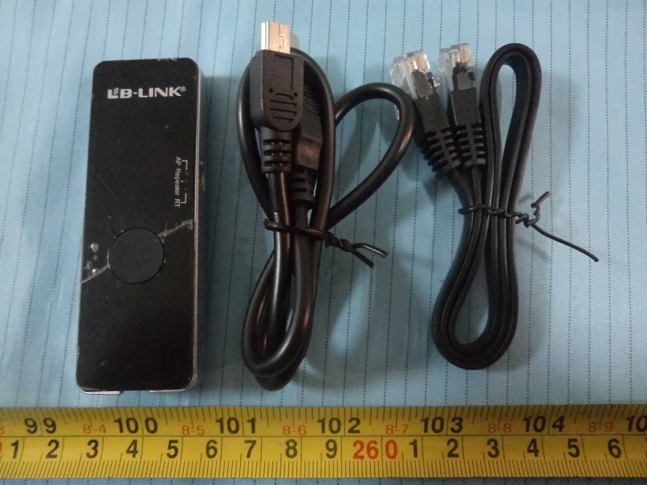
X2NBL-MP02
Jan 16, 2014150M Wireless N Wi-Fi Repeater
Equipment Class
DTS - Digital Transmission System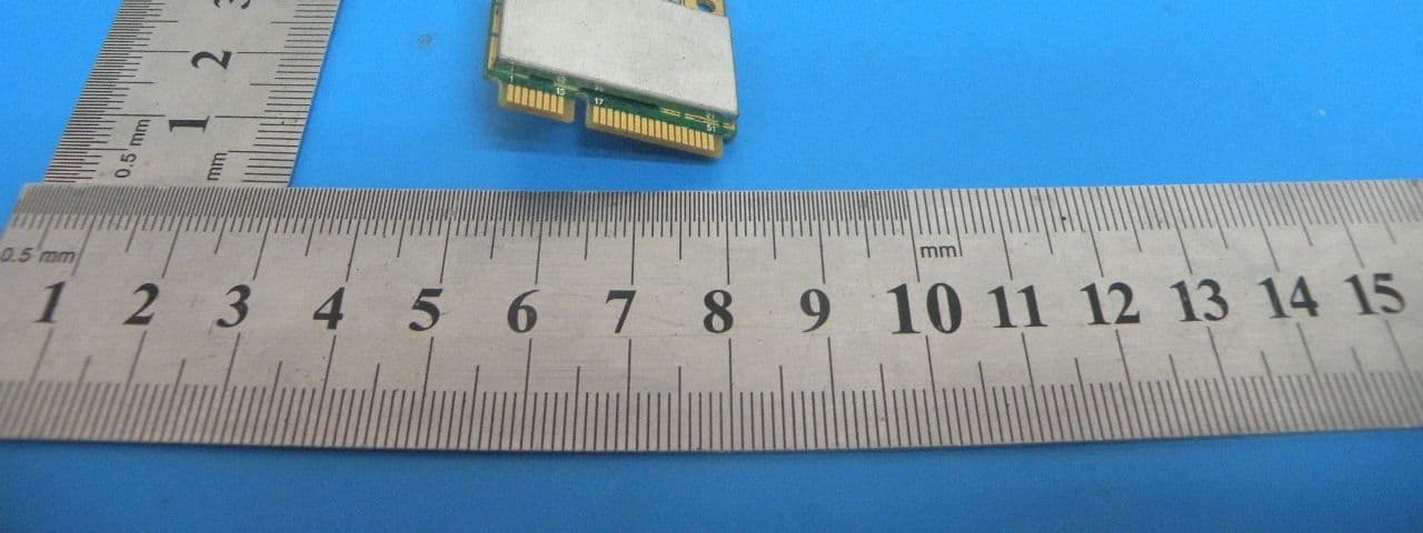
X2NBL-LW08-5
Oct 24, 2013WLAN 11b/g/n MINI PCIE MODULE
Equipment Class
DTS - Digital Transmission System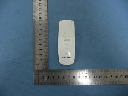
X2NBL-MP01
Mar 20, 201211N 150M WIRELESS Router
Equipment Class
DTS - Digital Transmission System
X2NBL-LW02-2
Jan 12, 2012wifi module
Equipment Class
DTS - Digital Transmission System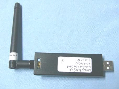
X2NBL-LWXX
Dec 23, 2009WIRELESS LAN CARD
Equipment Class
DTS - Digital Transmission System