X3U-TK110GPS Vehicle Tracker
TOPTEN ELECTRONICS TECHNOLOGY LIMITED
Click to zoom
Application Details
- Equipment Class
- PCB - PCS Licensed Transmitter
- Date of Grant
- Feb 02, 2010
- Application Purpose
- Original Equipment
- Date of Application
- Feb 01, 2010
- Equipment Note
- GPS Vehicle Tracker
- Frequency Range
- 1850.20000000 - 1909.80000000
- Country
- China
Documents & Files
Document Text
Text extracted from the exhibit documents filed with the FCC. Open a document above to read the original.
Users Manual
GPS Vehicle Tracker USER MANUAL (Model: TK110) Version 4.0 (Date: Jan. 2010) GPS Vehicle Tracker User Manual Page 1 CONTENT Preface............................................................................................................................... 2 Functions & Features ........................................................................................................ 3 Explanation on SMS Message .......................................................................................... 4 How to Operate It..............................................................................................................5 Arm/Disarm by Phone Calling .....................................................................................................5 SMS Control Instructions .............................................................................................................5 Authorize the Alert-received Mobile ............................................................................................5 SOS Anti-robbery Alert ................................................................................................................8 Movement Alert............................................................................................................................8 Geo-Fence Alert ...........................................................................................................................9 Over-speed Alert...........................................................................................................................9 The Setting for GPRS Connection..............................................................................................10 Re-define the Alert Text in other languages ............................................................................... 11 How to Track the Car .................................................................................................................12 Specifications ..................................................................................................................12 FAQs & Troubleshooting ................................................................................................ 13 Installation....................................................................................................................... 14 Packing List(Standard Package)............................................................................................14 Wiring Diagram ..........................................................................................................................15 Important Notice on Installation.................................................................................................16 Appendix I: How to Track the Car.................................................................................. 17 GPS Vehicle Tracker User Manual Page 2 Preface This Mini GPS Vehicle Tracker is the most cost-effective device to track your vehicle or the other objects. It has very small size, so it can be installed in very secret place. The installation & usage is very easy. This Mini GPS tracker communicates with user by SMS, not by GPRS, so it can work alone & the management center is not a must. It is specially designed for individual vehicles, user could use any GSM mobile phone to supervise, control and locate the car without the third party. On the other hand, if the management center is set up, many useful & interesting functions can be realized, such as monitoring many vehicles together by map, converting the GPS coordinate into the real address automatically. If user has MAPINFO map with detailed landmarks, the software can translate the car’s location automatically into the real physical address (such as city name, street name, building, etc.), then send this real physical address to user’s mobile by SMS. Read it Firstly: Please read this manual thoroughly before you use the device; please keep it for future reference. Attention: Please keep the device away from the water, humidity, high temperature, heavy dust or strong magnetism. Warning: We strongly suggest user let the professional car electrician to install the system. GPS Vehicle Tracker User Manual Page 3 Functions & Features (1) Check the car’s location, speed & direction via SMS; (2) Cut off the car power/fuel supply by SMS, to stop the car; (3) Movement Alert: Once the car is parked, you can send the SMS instruction to put the system in movement alert status. Then, if the car moves, the system will send SMS to inform you. It is a very useful function, which enables the tracker to work as the car alarm too; (4) Geo-fence Alert: User can set a certain zone by SMS, once the vehicle runs over the fence, the alarm will send SMS to inform you; (5) Over-speed Alert. User can set a certain speed limitation by SMS. Once the vehicle is running over this speed, the system will send SMS to inform you; (6) Built-in rechargeable backup battery. If the system’s main power supply is cut off or low enough, system will send SMS to warn you; (7) Two kinds of location information; user could locate the precise location by GPS. If there is no GPS signal, user could also locate the car by CPS (cellular positioning system - located by GSM network) (8) Monitor the voice around the car via telephone; (9) Anti-robbery switch, send out SMS for help in case of hijack; (optional function) (10) Track the car by SMS or by online mapping (The software is optional). (11) Flexible design, the system can work alone without support of center. If the center is set up, the functions can be much stronger, you can monitor & control many vehicles in the center, and the information of vehicle’s location can be more detailed and friendly. (12) Anti-tamper design in small size, stable, reliable & easy installation. (13) Support SMS & GPRS communication (14) The Alert Text in SMS can be re-defined in different languages. GPS Vehicle Tracker…
Text truncated - open the document above for the full version.
Block Diagram
MCU (Atmega64) 3.6864MHz GPS module (SIRF III) GSM module (SIM340DZ) Cut-off-Fuel loop Control output MIC Monitoring interface The Circuit’s Frame of TK110 SOS Signal input Door switch Detect & input Power supply Control output Ignition switch Detect & input Power-off Detect & input Vibration Sensor Detect & input Ultrasonic Sensor Detect & input GPS antenna GSM antenna
Cover Letter(s)
January 5, 2010 Nemko Canada Inc 303 River Road Ottawa, Ontario, Canada K1V 1H2 Attn: Director of Certification Authority to Act as Agent On our behalf Topten electronics Technology Limited, I appoint Shenzhen Certification Technology Service Co.,Ltd , (Name and address,person). to act as our agent in the preparation of this application for equipment certification. I certify that submitted documents properly describe the device or system for which equipment certification is sought. I also certify that each unit manufactured, imported or marketed, as defined in the Federal Communications Commission’s regulations will have affixed to it a label identical to that submitted for approval with this application. For instances where our authorized agent signs the application for certification on our behalf, I acknowledge that all responsibility for complying with the terms and conditions for certification, as specified by Nemko Canada Inc, still resides with Topten electronics Technology Limited ( applicant name and address). Dated this January 5, 2010 20 Agency agreement expiration date: Usually Give 8 - 12 Months By: Kenny leung Signature Printed Title: Commercial Director On behalf of : (Company Name) Topten electronics Technology Limited Telephone: +86-20-38351400
External Photos
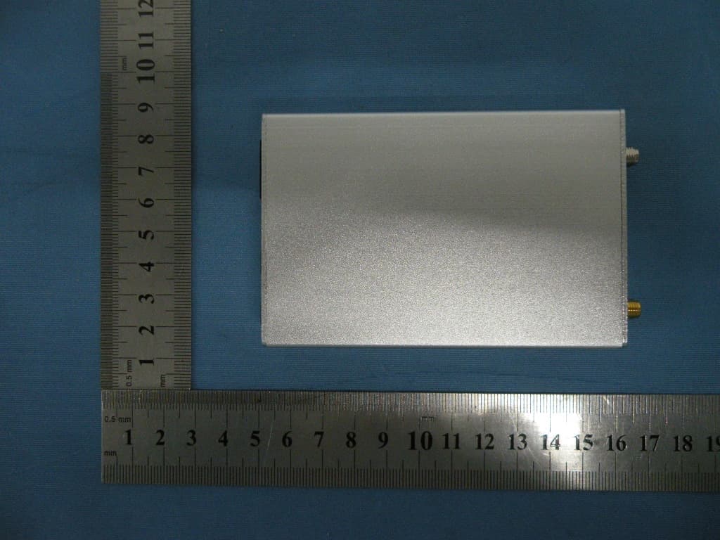
Full View To p Vi e w Bottom View Front View Rear View
ID Label/Location Info
FCC ID: X3U-TK110 Model No.: TK110 Manufacturer: Topten electronics Technology Limited
ID Label/Location Info
Label location
Internal Photos
GPRS ANTENNA GSM ANTENNA
Operational Description
Product description 1. Circuit Descriptions of GPS Vehicle Tracker(For TK110) (1) MCU chip, real-time reads the latitude and longitude output of GPS module (2) MCU chip, real-time listen and read the commands output of the SIM340DZ. (3) Through the transistor B772, MCU controls external relay to cut off / restore the fuel supply loop (4) Once MCU detects the signal from engine ignition switch, it will send out alert message. (5) Once MCU detects the signal of cut-off power supply lines, it will send out alert message. (6) Once MCU detects the voltage output signal from vibration sensor, it will send out alert message. (7) Once MCU detects the signal of the door switch, it will send out alert message. (8) Once the SOS button is pressed down, MCU will detect the signal & send out alert message for help. (9) After receipt monitoring command, MCU connects monitoring circuit to carry out monitoring. (10) The MCU Frequency is 3.6864MHZ 2. Main function of device (1) Check the car’s location, speed & direction via SMS; (2) Cut off the car power/fuel supply by SMS, to stop the car; (3) Movement Alert: Once the car is parked, you can send the SMS instruction to put the system in movement alert status. Then, if the car moves, the system will send SMS to inform you. It is a very useful function, which enables the tracker to work as the car alarm too; (4) Geo-fence Alert: User can set a certain zone by SMS, once the vehicle runs over the fence, the alarm will send SMS to inform you; (5) Over-speed Alert. User can set a certain speed limitation by SMS. Once the vehicle is running over this speed, the system will send SMS to inform you; (6) Built-in rechargeable backup battery. If the system’s main power supply is cut off or low enough, system will send SMS to warn you; (7) Two kinds of location information; user could locate the precise location by GPS. If there is no GPS signal, user could also locate the car by CPS (cellular positioning system - located by GSM network) (8) Monitor the voice around the car via telephone; (9) Anti-robbery switch, send out SMS for help in case of hijack; (optional function) (10) Track the car by SMS or by online mapping (The software is optional). 3. Specifications Size of the main unit: 7.5*5.4*2.5 (CM) Weight of the main unit: 0.1KG Working temperature: -20 ~ 65°C Humidity: 0 ~ 95% Radio technology: GSM/GPRS 850/900/1800/1900 Frequency: GSM 850: 824.2MHz—848.8MHz GSM900:880.2MHz—914.8MHz GSM1800:1710.2MHz—1784.8MHz GSM1900:1850.2MHz—1909.8MHz Modulation type: GMSK RF Power: GSM850/900: 32dBm±2 GSM1800/1900: 29dBm±2 GPS chip: Latest SiRF-Star III chipset GPS Receive frequency 1575±5MHz GSM antenna and Gain External Patch Antenna, 3.5dBi Gain,SMA-B connector GPS antenna’s Gain Antenna Gain: -3dBic at 10°; 3.5dBic at zenith; Amplified Gain: 27dB typ. Working voltage: 12VDC/ or 24 VDC for Battery Power Consumption: Working current: ≤250mA; Static current: ≤60mA; Peak current: 300mA; Internal Backup battery Rechargeable 3.7V 750mAh Li-ion battery
Parts List/Tune Up Info
MODEL:TK110Comment Pattern Quantity Components Chip Capacitors 0603 4 C15,C16,C17,C30 Chip Resistors 0603 2 R13,R20 Chip Resistors 0603 1 R40 Chip Resistors 0603 13 R14, R26, R28, R31, R32, R32,R33, R33, R34, R35, R36, R37,R38 Chip Resistors 0603 1 R29 Chip Resistors 0603 5 R15,R22,R24,R41,R44 Chip Resistors 0603 1 R39 Chip Capacitors C1206 3 C10,C12,C18 Chip Resistors 0603 2 R18,R27 12PIN Interface Block J12 1 CN1 SMD Transistor SOT-23 1 Q8 Chip Resistors 0603 5 R12,R19,R42,R43,R45 SMD diode d1206-1 1 D3 Connectors CN2 1 FR Chip Resistors 0805 1 R21 Chip Resistors 0603 1 R25 Chip Resistors 0603 1 R23 Chip Resistors 0603 1 R16 Chip Resistors 0603 1 R16 Chip Capacitors 0603 2 C13,C14 SMD Transistor SOT-23 2 Q4,Q5 Crystal XTAL-1 1 XTL Chip Resistors 0603 1 R17 40pin Interface TC35I 1 P2 Inductance L1 1 L2 Chip Capacitors 6032(2) 1 C11 Chip Capacitors rb0.4 1 C3 Chip Resistors 0603 1 R30 Chip Resistors 0603 2 R31 SMD Transistor SOT-23 1 Q2 AP1501 CN6 1 VTR IC LCC64 1 IC3 Diode 2012A 1 D2 SMD TRANSISTOR J3-1 1 Q1 GPS Module VPN11513 1 G1 IC S0 8 1 IC5 IC S0-8 1 IC4 LED 0805 3 CPU,GLED,GSM power IC SOT25 1 LDO SIM card connector CN8 1 S1 Diode D1206-1 3 D1,D4,D5 SMD Transistor SOT-23 9 Q3,Q5,Q6,Q7,Q9,Q10,Q11,Q12,Q13 Bettery Switch J3 1 SW1 POwer Transposon J4 1 X1
Parts List/Tune Up Info
TOPTEN ELECTRONICS TECHNOLOGY LIMITED Add: Room2007, Tower B, Gaoke Building, 908 Tianhe North Road, Guangzhou, China TEL: +86-20- 38351400, 38351401 FAX: +86-20-38351400 (ext.606) http://www.t10.cn . Email: [email protected] Letter of Certification This is to formally certify that: The tune up procedures of GPS vehicle Tracker (Model TK110) is not open to end user. The end user is not allowed to perform final tune. All the power and frequency set up were finished at the manufacturer stage. _____________________________________ (Commercial Director: Kenny Leung) Date: Feb.1, 2010 TOPTEN ELECTRONICS TECHNOLOGY LIMITED
RF Exposure Info
RF Exposure Statement 1. Standard Applicable According to 1.1307 (b)(1), systems operating under the provisions of this section shall be operated in a manner that ensure that the public is not exposed to radio frequency energy level in excess of the Commission’s guideline. 2. Result: This device is not portable device and for normal use, the operator will be 20cm away form the device. SAR measurement is not necessary. 3. MEP estimation at 25cm Mode CH Frequency (MHz) PK Output power (dBm) Output power (mW) antenna Gain (dBi) antenna Gain(linear) MPE 128 824.2 31.7 1479.11 3.5 2.24 0.4218 190 836.6 31.69 1475.71 3.5 2.24 0.4209 GSM 850 251 848.8 31.65 1462.18 3.5 2.24 0.4170 512 1850.2 29.1 812.83 3.5 2.24 0.2318 661 1880.0 29.03 799.83 3.5 2.24 0.2281 PCS 1900 810 1909.8 29.13 818.46 3.5 2.24 0.2334
Schematics
123456 A B C D 6 54321 D C B A Title NumberRevisionSize B Date:25-Jan-2010Sheet of File:E:\项目管理\汽车防盗器\GPS汽车定位器\GPS-Protel\Vat-2009.DDBDrawn By: 1 2 3 4 5 6 7 8 9 10 11 12 13 14 15 16 1920212223242526272829303132 33 34 35 36 37 38 39 40 41 42 43 44 45 46 47 48 49505152535455565758596061626364 1718 U8 ATMEGA64L 123456789 10 11 12 13 14 15 16 17181920212223242526 27 28 29 30 31 32 G1 GPS R19 1K D3 4004 R? 2.7K 12 34 56 78 910 1112 CN HEADER 6X2 CN6 CN6 R? 100K Q? 1AM R? 100K GND Q? 1AM R? 100K CN2 CN2 R? 100K CN1 CN1 R? 100K CN4 CN4 R? 100K Q? 1AM Q1 4.7K D? 4148 1 2 3 SW CON3 3V 1 2 BAT CON2 GND Q? 1AM GND R? 100K R? 100K 12Vout C9 220uF/50V D? 4007 12Vin 12 34 PW HEADER 2X2 123 Q2 B772P R14 2.7K Q? 1AM GND R? 100K 1 2 3 4 56 7 8 9 10 IC4 LTBVT R21 100K C6 ? GND L1 4R7 1 2 3 45 6 7 8 IC2 IRF7404 R7 10K R4 2.7K C8 ? D5 B240 R8 51K GND R9 15K C5 ? R10 120K R11 51K C14 22uF GND R24 2R2 C10 ? 3V 4.2V D? 1N5817 3V GND CPU_7 CPU_7 Q? 1AM GND R? 100K R? 100K CN8 CN8 R? 2.7K D2 ? CPU_15 CPU_15 CPU_8 CPU_8 Q? 1AM GND R? 100K R? 100K CN5 R? 100K CN5 GND CPU_9 Q? 1AM GND R? 100K R? 100K CN9 CPU_9 GND CN9 CPU_10 Q? 1AM GND R? 100K R? 100K CN12 CN12 CPU_10 CPU_11 CPU_11 R21 4.7K 1 2 34 5 IC6 RT9013 GND C15 100uF R22 100K R? 10K C? 1uF 3V 3V CPU_58 CPU_58 GND CPU_RST CPU_RSTCPU_17 CPU_17 D1 S4 R18 2.7K CN10 CN10 GND 3V GND X1X2 XT 7.3728MHz X1X2 C3 20pF C4 20pF GND CPU_27 123456789 1112151617 20 21 22 23 24 25 26 27 28 29 30 31 32 33 34 35 36 37 38 39 40 41 42 43 44 45 46 47 48 M? SIM340DZ CPU_27 CPU_28 CPU_28 CPU_35 CPU_35 1 2 3 4 5 USB CON5 CPU_37 CPU_37CPU_38 CPU_38CPU_39 CPU_39 R1 2.7K CPU_40 CPU_40 R2 100 R3 100 GNDCPU_41 CPU_41 GND CPU_43 CPU_43 CPU_45 CPU_45 3V GND C11 ? GND GPS_VCC C13 ?C12 100uF GPS_VCC GND 1 2 GPS CON2 GND GND GND GND GND 12 GSM CON2 GND 1 2 3 4 5 6 SIM CON6 SIM1 SIM1 SIM6 SIM6 SIM5 SIM5 SIM4 SIM4 C1 ? C2 ? GND GND C7 100uF 4.2V GPS MODULE (VPN1513 SIRFIII) GSM MODULE (SIMCOM340DZ) CPU (ATMEGAL64-8AU) GPS Antenna I/O GSM Antenna I/O
Test Report
Shenzhen Certification Technologh Service Co., Ltd 3F, Bldg27,Area A, Tanglang Industrial Zone, Xili Town, Nanshan District, ShenZhen, Guang dong, P.R. China. FCC ID: X3U-TK110 Page 1 of 39 TEST REPORT FCC ID: X3U-TK110 Applicant:Topten electronics Technology Limited Address : Room2007,Tower B,Gaoke Building, 908 Tianhe North Road, Guangzhou,China Equipment Under Test(EUT): Name : GPS Vehicle Tracker Model : TK110 In Accordance with: FCC PART 2; FCC PART 22H; FCC PART 24E Report No : STE100104007 Date of Test : Jan 05---06, 2010 Date of Issue : Jan 07, 2010 Test Result: PA S S In the configuration tested, the EUT complied with the standards specified above Authorized Signature ___________________________ (Mark Zhu) General Manager The manufacture should ensure that all the products in series production are in conformity with the product sample detailed in this report. If the product in this report is used in any configuration other than that detailed in the report, the manufacturer must ensure the new system complies with all relevant standards. Any mention of Shenzhen Certification Technology Service Co., Ltd. Or test done by Shenzhen Certification Technology Service Co., Ltd. Approvals in connection with, distribution or use of the product described in this report must be approved by Shenzhen Certification Technology Service Co., Ltd. Approvals in writing. Report No.:STE100104007 FCC ID: X3U-TK310 Page 2 of 39 Contents 1. General Information ...............................................................................................................4 1.1. Description of Device (EUT) ..........................................................................................4 1.2. Test Lab information .......................................................................................................4 2. Summary of test ......................................................................................................................5 2.1. Summary of test result ....................................................................................................5 2.2. Assistant equipment used for test....................................................................................5 2.3. Test mode ........................................................................................................................6 2.4. Test Environment Conditions..........................................................................................6 2.5. Measurement Uncertainty (95% confidence levels, k=2) ...............................................6 2.6. Test Equipment ...............................................................................................................7 3. Conducted Output power .......................................................................................................8 3.1. Block Diagram of Test Setup ..........................................................................................8 3.2. Limit................................................................................................................................8 3.3. Test Procedure.................................................................................................................8 3.4. Test Result.......................................................................................................................8 4. Radiated Output power ..........................................................................................................9 4.1. Block Diagram of Test Setup ..........................................................................................9 4.2. Limit................................................................................................................................9 4.3. Test Procedure.................................................................................................................9 4.4. Test Result.....................................................................................................................10 5. Occupied Bandwidth ............................................................................................................11 5.1. B lock Diagram of Test Setup ....................................................................................... 11 5.2. Limit.............................................................................................................................. 11 5.3. Test Procedure............................................................................................................... 11 5.4. Test Result.....................................................................................................................12 5.5. Orginal test data ............................................................................................................12 6. Frequency stability................................................................................................................16 6.1. Block Diagram of Test Setup ........................................................................................16 6.2. Limit..............................................................................................................................16 6.3. Test Procedure...............................................................................................................16 6.4. Test Result.....................................................................................................................17 7. Conducted spurious emissions .............................................................................................19 7.1. Block Diagram of Test Setup ........................................................................................19 7.2. Limit..............................................................................................................................19 7.3. Test Procedure.....................................................…
Text truncated - open the document above for the full version.
Contact Information
Applicant
Kenny leung(Commercial Director)
Test Firm
Shenzhen Certification Technology Service Co.,LtdMark Zhu
Technical Specifications
| # | Rule Parts | Frequency Range | Power Output | Emission | Tolerance |
|---|---|---|---|---|---|
| 2 | 24E | 1.85 GHz - 1.91 GHz | 818.00 mW | 315KGXW | 39 Hz |
Other Applications from TOPTEN ELECTRONICS TECHNOLOGY LIMITED
X3U-TK210
Dec 21, 2011Wireless GPS Car Alarm
Equipment Class
PCB - PCS Licensed Transmitter
X3U-MT113
Dec 18, 2011GPS Motorcycle/Vehicle Tracker
Equipment Class
PCB - PCS Licensed Transmitter
X3U-TK310
Feb 02, 2010GPS Vehicle Tracker
Equipment Class
PCB - PCS Licensed Transmitter